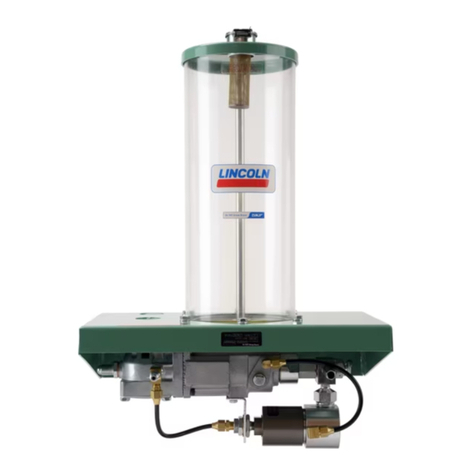
SKF Lincoln J Series Instruction Manual

User and maintenance instructions
Model , series “J”
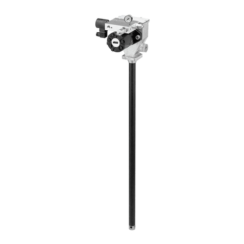
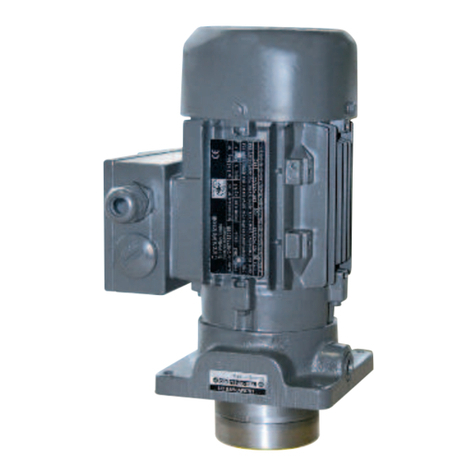
Air operated grease pump
Date of issue November
Form number
Version

*Indicates change
Contents
Declaration of Incorporation* . . . . . . .
U.K. Declaration of Incorporation* . . .
Safety* . . . . . . . . . . . . . . . . . . . . . . . . . .
Specifications . . . . . . . . . . . . . . . . . . . . .
Description. . . . . . . . . . . . . . . . . . . . . . .
Fill reservoir . . . . . . . . . . . . . . . . . . . . .
Dimensions . . . . . . . . . . . . . . . . . . . . . . .
Lubricate air valve mechanism . . . . . .
Change pump to new series
\follower configuration. . . . . . . . . . . . .
Prime system. . . . . . . . . . . . . . . . . . . . .
Supply lines. . . . . . . . . . . . . . . . . . . . . . .
Feeder lines. . . . . . . . . . . . . . . . . . . . . . .
Operation . . . . . . . . . . . . . . . . . . . . . . . .
Vent valve. . . . . . . . . . . . . . . . . . . . . . . .
Safety unloader. . . . . . . . . . . . . . . . . . .
Model . . . . . . . . . . . . . . . . . . . . . .
Service parts. . . . . . . . . . . . . . . . . . . . . .
Warranty . . . . . . . . . . . . . . . . . . . . . . . . .

Declaration of Incorporation* DOCUMENT NUMBER
404402.DoI
Manufacturer name/address:
Lincoln Industrial Corporation
N. Hanley Road
St. Louis, MO U.S.A.
TEL: + () - FAX: + () -
Authorized to compile the technical file:
SKF Lubrication Systems Germany GmbH
Heinrich-Hertz-Straße -
Walldorf, Germany
TEL: + () -
EMAIL: robert.collins@skf.com WEBSITE: www.skf.com
This Declaration of Incorporation is issued
under sole responsibility of the
manufacturer. Lincoln Industrial Corporation
hereby declares that the partly completed
machinery stated below:
Name: Series pumps
Model number(s):
Description:
Year of CE:
in its intended use, is in conformity with the
relevant union harmonization legislation:
Machinery Directive //EC
(article Partly Completed Machinery)
and conforms to the following harmonized
standards:
EN ISO :
Hydraulic fluid power - General rules and
safety requirements for systems and their
components
EN ISO :
Safety of machinery. General principles
for design. Risk assessment and risk
reduction
EN ISO :
Pneumatic fluid power. General rules and
safety requirements for systems and their
components
EN ISO :+A:
Pumps and pump units for liquids -
Common safety requirements
EN :+A:
Liquid pumps. Safety requirements.
Procedure for hydrostatic testing
I, the undersigned of Lincoln Industrial Corporation, do hereby declare that the equipment specified above, in its intended use, conforms to
the requirements of the above EC Directive(s).
___________________________________
Robert Collins
Technical Compliance Manager
St. Louis, MO, U.S.A.
The following EHSR (Essential Health &
Safety Requirements) have been applied:
..a – ..b – ..c – .. – .. –
.. – .. – .. – .. – .. – .. –
.. – .. – .. – .. – . – .. –
... – .. – ..
The manufacturer maintains a technical
construction file containing test reports and
product documentation:
Technical file summary sheet number:
Air-operated chassis pump (SeriesJ)
RA
// *Indicates change

U.K. Declaration of Incorporation* DOCUMENT NUMBER
UK404402CA
Manufacturer name/address:
Lincoln Industrial Corporation
N. Hanley Road
St. Louis, MO U.S.A.
TEL: + () - FAX: + () -
Authorized to compile the technical file:
SKF (U.K.) Limited
Canada Close
Banbury, Oxfordshire, OX RT, GBR
EMAIL: robert.collins@skf.com WEBSITE: www.skf.com
This U.K. Declaration of Incorporation is
issued under sole responsibility of the
manufacturer. Lincoln Industrial Corporation
hereby declares that the partly completed
machinery stated below:
Name: Series pumps
Model number(s):
Description:
Year of CE:
in its intended use, is in conformity with the
relevant union harmonization legislation:
Supply of Machinery (Safety) Regulations
(S.I. :)
and conforms to the following harmonized
standards:
EN ISO :
Hydraulic fluid power - General rules and
safety requirements for systems and their
components
EN ISO :
Safety of machinery. General principles
for design. Risk assessment and risk
reduction
EN ISO :
Pneumatic fluid power. General rules and
safety requirements for systems and their
components
EN ISO :+A:
Pumps and pump units for liquids -
Common safety requirements
EN :+A:
Liquid pumps. Safety requirements.
Procedure for hydrostatic testing
I, the undersigned of Lincoln Industrial Corporation, hereby declare that the equipment specified above, in its intended use, conforms with the
Essential Health and Safety Requirements of U.K. legislation Supply of Machinery (Safety) Regulations No. Annex I, Declaration of
Incorporation by the time of placing it on the market.
___________________________________
Robert Collins
Technical Compliance Manager
St. Louis, MO, U.S.A.
The following EHSR (Essential Health &
Safety Requirements) have been applied:
..a – ..b – ..c – .. – ..
– .. – .. – .. – .. – .. – ..
– .. – .. – .. – .. – . – .. –
... – .. – ..
The manufacturer maintains a technical
construction file containing test reports and
product documentation:
Technical file summary sheet number:
RA
//
Air-operated chassis pump (SeriesJ)
*Indicates change

Safety*
The assembly must be installed, maintained
and repaired exclusively by persons familiar
with the instructions.
Always disconnect power source
(electricity, air or hydraulic) from the
equipment when it is not being used.
This equipment generates high pressure.
Extreme caution should be used when
operating this equipment as material leaks
from loose or ruptured components can
inject fluid through the skin and into the
body. If any fluid appears to penetrate the
skin, seek attention from a doctor
immediately. Do not treat injury as a simple
cut. Tell attending doctor exactly what type of
fluid was injected.
Any other use not in accordance with
instructions will result in loss of claim for
warranty or liability.
• Do not misuse, over-pressurize, modify
parts, use incompatible chemicals, fluids,
or use worn and/or damaged parts.
• Do not exceed the stated maximum
working pressure of the equipment or of
the lowest rated component in your
system.
• Always read and follow the manufacturer’s
recommendations regarding fluid
compatibility, and the use of protective
clothing and equipment.
• Failure to comply may result in personal
injury and/or damage to equipment.
CAUTION
Do not operate equipment without
wearing personal protective gear.
Wear eye protection. Protective
equipment such as dust mask, non-skid
safety shoes, hard hat, or hearing pro-
tection used for appropriate conditions
will reduce personal injuries.
Failure to comply may result in light
personal injury.
WARNING
Do not allow any body part
to be trapped by equipment.
Body parts can be crushed
by subassemblies during
operation.
Failure to comply may result in death
or serious physical injury.
WARNING
Do not allow fluid to leak
onto floor when operating
equipment. If spill occurs,
clean any fluid on floor before continuing
operation.
Failure to comply may result in death
or serious personal injury.
WARNING
Do not use this equipment to supply,
transport, or store hazardous
substances and mixtures in accordance
with annex I part - of the CLP
regulation (EG /) or HCS
CFR . marked with GHS,
GHS and GHS hazard pictograms
shown:
Explanation of signal
words for safety
NOTE
Emphasizes useful hints and
recommendations as well as
information to prevent property damage
and ensure efficient trouble-free
operation.
CAUTION
Indicates a dangerous situation that can
lead to light personal injury if
precautionary measures are ignored.
WARNING
Indicates a dangerous situation that
could lead to death or serious injury if
precautionary measures are ignored.
DANGER
Indicates a dangerous situation that will
lead to death or serious injury if
precautionary measures are ignored.
WARNING
Do not operate equipment
without reading and fully
understanding safety
warnings and instructions.
Failure to follow warnings and
instructions may result in serious injury.
*Indicates change
) Based on lubricants free of entrapped air. Aerated lubricants will reduce output of pump.
Specifications
Lubricant output Reservoir Air Lubricant Lubricant operating pressure
Ratio Per cycle ) Per minute at psi (60 bar) capacity inlet outlet Type of system Minimum Maximum Recommended
: . in
(1,8 cm3)
in(197 cm3) lbs.
(5,4 kg)
/in
NPTF
(internal)
/in
NPTF
(internal)
SL- psi
(128 bar)
psi
(245 bar)
psi (172 bar)
SL- psi
(128 bar)
psi
(245 bar)
psi (172 bar)
SL- psi
(83 bar)
psi
(245 bar)
psi (103 bar)
SL- psi
(83 bar)
psi
(245 bar)
psi (103 bar)
7
2)
68
9
10
11
12
1
2
3
4
5
13
14
15
16
17
18
23
24
26
31
19
20
21
29 28
30
27
4)
22
25
3)
9 in
(228 mm)
1)
Description
Pump is used as pumping unit for
centralized lubrication system having single
line circuit of SL-, SL-, SL- or
SL- injectors.
It is an air operated reciprocating pump
that discharges . in(1,8 cm3)of
lubricant into circuit for each pump cycle.
Fill reservoir
Use manual filler pump to fill
reservoir through filler fitting () in
pump body.
Attach coupler on delivery hose to
filler fitting.
Stroke filler pump handle until there is
weepage at air vent hole in reservoir.
Lower portion of follower () must rise
beyond air vent hole to expel entrapped
air from lubricant.
NOTE
Caution should be used when filling reservoir
as extreme pressure may cause damage to
reservoir and follower assembly.
NOTE
Amount of lubricant discharged is based on
lubricants free of entrapped air. Aerated
lubricants will reduce output of pump.
Fig. IPB
) Vent hole
) Torque to ft.lbf (20 Nm).
) Restrictor (not furnished with pump) may be added between () and () to reduce pump noise.
Pump speed and output per minute will be reduced accordingly.
) Torque to to ft.lbf. (16 to 23 Nm).

32
33
36
37
38
39
40
41
42
43
44
35
34
38
80
81
82 83
84
46
85
86
/ in NPTF
14
/ in NPTF
34
/ in NPTF
34
/
in
( mm)
/
in
( mm)
/
in
( mm)
/
in
( mm)
/ in NPTF
18
/ in NPTF
14
1)
) Vent valve ()
Fig.
Dimensions

Lubricate air valve
mechanism
Disconnect air to pump and remove
four cover screws (), cover plate ()
and cover plate gasket ().
Remove and disassemble air valve
casting () from pump.
Air valve casting should be cleaned or
flushed to remove any chips or other
foreign particles prior to reassembly.
Before replacing toggle assembly (),
pack cavity with grease.
Use /oz (44,3 ml) of NLGI water
repellent grease.
Replace cover gasket (), cover ()
and screws (). Tighten to avoid air
leaks.
Periodic inspection of parts at least
once each year is advisable for
optimal use.
Change pump to new
series follower
configuration
Use follower upgrade kit .
Remove bushing (), washer
assembly () and retaining ring ().
Place follower washer on lower side of
follower packing (), making sure top
follower washer is still in place.
Place o-ring ()into bushing.
Place gasket () on bushing.
Place bushing and gasket into assem-
bled follower packing and washers.
Place drops of blue Loctite at
° apart on threads of bushing.
Assemble nut () to bushing and
tighten. Place hex of bushing in vice and
tighten nut to in-lbs (± in-lbs).
Prime system
Supply lines
Operate pump until lubricant starts to bleed
around vent plug to expel air pockets
trapped between pump and supply line
connection. Continue operating pump until
lubricant flows around any plug.
Feeder lines
Fill each feed line with lubricant before
connecting lines to outlets of injectors and
bearings to prevent having to cycle each
injector.
Operation
Lube cycle initiates when pump times out.
Air solenoid is energized to deliver air to
pump and vent valve. Pump dispenses
lubricant through injectors to bearings. Once
all bearings receive lubricant, pressure rises
in system to actuate pressure switch. When
pressure switch actuates, control is reset to
de-energize solenoid valve, cutting off air to
pump and vent valve. Pump stops, pressure
vents and pressure switch de-actuates.
Control begins timing toward next lube
event.
Vent valve
Vent valve () operates with compressed air
from same source that operates pump.
When pump is in operation, air pressure
keeps vent valve closed and lubricant is
directed through outlet to injectors.When air
to pump is shut off, vent valve opens and
supply line pressure vents back into
reservoir.
Safety unloader
Safety unloader () is provided at pump
outlet to prevent build-up of dangerously
high lubricant pressure in system. It is
factory set to open at approximately
psi to psi (259 to 293 bar).
WARNING
Safety unloader requires no adjustment
and should not be tampered with.
Failure to comply may result in death
or serious injury.

89
90
91
92 106
93
94
96
60
97
51
62
58
98
4)
31
99
100
101
5)
102
103
104
5)
87
88
1)
/ in NPTF
14
59
2)
61
3)
95
2)
59
2)
105
92
) Air exhaust port
) Torque to in.lbf. (3,3 to 4,5 Nm).
) Torque to in.lbf. (10 to 12 Nm).
) Assemble with Loctite # Blue.
) Tighten to to ft.lbf. (27 to 33 Nm).
Fig. IPB
Model

61
60
55
62
51
1)
45
46
47
/ in NPTF
14
48
49
50
52
53
54
56
58
57
63
64
65
66
67
68
69
70
71
72
73
74
75
76
77
78
79
47
77
2)
59
) Tighten to to ft.lbf. (13,5 to 20,3 Nm).
) Torque to to ft.lbf. (128 to 142 Nm).
Fig.
Model

) Included in repair kit.
) Recommended service parts inventory.
) Included in follower upgrade kit.
) Assemble with Loctite # Blue.
*Indicates change.
Service parts
Item Description Qty. Part no. Item Description Qty. Part no. Item Description Qty. Part no.
Gasket (nitrile) ° tube connector * Steel ball
Retaining ring Vent valve assembly Check housing
Lockwasher Support adapter Outlet body
Screw Bolt Plug
Bushing ) Straight tube
connector
Gasket ))
Plug button Lockwasher Outlet block
Nut Washer Gasket
Lockwasher Nylon tubing Air cylinder
Reservoir cap Gasket (Nitrile coated
fiber)
) Piston
Retainer washer Gasket Packing (Nitrile) )
Tie rod Washer Viton packing assembly
Reservoir (acrylic) Packing (Nitrile) Valve seat )
Follower spring Air piston bolt Valve body
Nut ) Gasket Needle )
Follower washer ) Trip sleeve )) Spring retainer
Follower Air valve casting Spring
O-ring (Nitrile) ) O-ring (Nitrile) )) Muffler cover
Gasket ) Seat )) Muffler
Base Trip rod pin )) Valve gasket (Nitrile) ))
Nipple Gasket ) Valve slide, seat and
gasket assembly
))
Tee Cap Valve guide plate ))
Plug Trip rod collar )) Spring
Filler fitting Screw Valve seat bolt
Straight tube connector Gasket (Neoprene) )) Cover
Check disc packing ) Screw ) Toggle assembly ))
Strainer Trip shoe )) Screw )
Adapter Trip rod )) Base casting
Washer Gasket (Nitrile) )) Gasket )
Nut Gasket )) Packing nut
Bracket Packing (Nitrile) )) Washer
Pipe plug Trip rod packing nut )) Packing (Nitrile) )
Air motor Bushing, plunger and
O-ring assembly
Packing cap
° tube connector O-ring Spring )
Nylon tubing O-ring )) Steel ball ))
Safety unloader ) Pump check disc ))
Reducer nipple Spring )

Troubleshooting
Problem Cause Solution
Pump operates continuously. Pump has lost prime. Examine lubricant supply. Refill reservoir
if necessary.
Air pocket trapped in lubricant. Loosen vent plug one turn. Allow pump to
operate until trapped air is pumped out.
Close vent plug.
Pump continues to operate without discharging
lubricant.
Pump check () and steel ball ()
fouled.
Remove and clean checks and check seats.
Vent valve () fouled. Replace vent valve.
Foreign material prevents needle ()
from seating properly.
Clean or replace parts.
Pump fails to operate. Air system is leaking. Verify air supply is connected.
Verify air system is not leaking.
Injectors fail to cycle. Leak in supply line. Examine lines and connections.

This page left intentionally blank.

This page left intentionally blank.

This page left intentionally blank.

skf.com | lincolnindustrial.com
® SKF and Lincoln are registered trademarks of the SKF Group.
© SKF Group
The contents of this publication are the copyright of the publisher and may not be reproduced (even
extracts) unless prior written permission is granted. Every care has been taken to ensure the accuracy
of the information contained in this publication but no liability can be accepted for any loss or damage
whether direct, indirect or consequential arising out of the use of the information contained herein.
November · Form Version
Warranty
The instructions do not contain any information on the warranty.
This can be found in the General Conditions of Sales, available at:
www.lincolnindustrial.com/technicalservice or www.skf.com/lubrication.
This manual suits for next models
1
Table of contents
Other SKF Water Pump manuals

SKF
SKF Lincoln FlowMaster II Instruction Manual

SKF
SKF Lincoln 274874 Product manual

SKF
SKF Lincoln HTL 201 User manual

SKF
SKF KFGL User manual

SKF
SKF FB User manual

SKF
SKF PAB Series User manual

SKF
SKF PVP-50-1G Technical document

SKF
SKF P215EEX User manual

SKF
SKF LINCOLN FlowMaster II A Series User manual

SKF
SKF 84-1731-4801 User manual
Popular Water Pump manuals by other brands

BUSCH
BUSCH RA 0010 C instruction manual

Crane
Crane Barnes 2SEV-L Series Installation and operation manual

Agilent Technologies
Agilent Technologies DS202 1Ph instruction manual

Kärcher
Kärcher GP 50 manual

wb compagnie
wb compagnie XC100009 manual

Johnson Pump
Johnson Pump SPX FLOW L750 LB instruction manual