manuals.online logo
Brands
  1. Home
  2. •
  3. Brands
  4. •
  5. Bonaldo
  6. •
  7. Indoor Furnishing
  8. •
  9. Bonaldo Chat User manual

Bonaldo Chat User manual

Chat design: Dondoli e Pocci
1scheda montaggio - assembly instruction - Aufbauanleitung - notice de montage
DTe s T a c i l i n d r i c a M8
cYlindrical Head M8
ZYlinderKOPF M8
TeTe cYlindriQUe M8
n° 4
in s e r T O g a M b a
leg inserT
beineinsaTZsTÜcK
PlaQUeTTe Pied
n° 4
C
cH i a v e ab r U g O l a 4
allen KeY 4
iMbUsscHlÜssel 4
cle allen 4
n° 1
B
Tavolo
Table
Tisch
Table
Kit di montaggio / Assembly kit / Montagezubehör / Kit de montage
aTTenZiOne:
Ma n e g g i a r e c O n M a n i P U l i T e .
aTTenTiOn:
Ha n d l e w i T H c l e a n H a n d s .
acHTUng:
MiT s a U b e r e n Hä n d e n a n F a s s e n .
aTTenTiOn:
Ma n i P U l e r a v e c l e s M a i n s P r O P r e s .
vi T e M6
screw M6
scHraUben M6
vis M6
n° 8
A
Chat design: Dondoli e Pocci
scheda montaggio - assembly instruction - Aufbauanleitung - notice de montage2
1
Togliere il telaio dall’imballo e capovolgerlo come
in Fig.1. Montare i 4 inserti (L) fissando le viti M8,
facendo molta attenzione al senso di montaggio
(Fig. 4-5). I due fori (F) del lato piatto vanno sem-
pre a coincidere con il buco (B) dell’angolo del
tavolo (Fig. 2), non vanno perciò montati con il
lato scanalato verso l'interno (Fig.3). Inoltre, gli
inserti (L), vanno sempre inseriti con i fori rivolti
verso l'interno del telaio (Fig. 6).
I
Remove the frame from the packaging and over-
turn it as shown in Fig. 1. Mount the 4 inserts (L)
tightening the M8 screws. Pay attention to the
assembly direction (Figs. 4-5). The two holes (F) of
the flat side must be always aligned with the hole
(B) in the corner of the table (Fig. 2). Therefore,
they shall not be mounted with the grooved side
inwards (Fig. 3). In addition, the inserts (L) must
always be inserted with the holes facing the in-
ternal part of the frame (Fig. 6).
GB
Das Gestell aus der Verpackung nehmen und
umdrehen (siehe Abb.1). Die 4 Einsatzstücke (L)
montieren. Dazu die Schrauben M8 anziehen und
auf die Montagerichtung achten (Abb. 4-5). Die
beiden Löcher (F) auf der Plattenseite müssen im-
mer mit der Öffnung (B) der Tischecke (Abb. 2)
übereinstimmen. Sie werden daher nicht mit der
Kanalseite nach Innen montiert (Abb. 3). Ferner
die Einsatzstücke (L) immer mit den Öffnungen in
das Rahmeninnere geben (Abb. 6).
D
Enlever la châssis de l’emballage et la retourner
comme il est indiqué sur la Fig.1. Monter les 4 pla-
quettes (L) en fixant les vis M8, et en faisant très
attention au sens du montage (Fig. 4-5). Les deux
trous (F) du côté plat doivent toujours coïncider
avec le trou (B) de l’angle de la table (Fig. 2), ils ne
doivent donc pas être montés avec le côté canne-
lé vers l’intérieur (Fig.3). En outre les plaquettes
(L) doivent toujours être insérées avec les trous
tournés vers l’intérieur du châssis (Fig. 6).
F
1
F
B
2 3
4 5
L
6
L
L
L
L
Chat design: Dondoli e Pocci
3scheda montaggio - assembly instruction - Aufbauanleitung - notice de montage
2I
Montare le 4 gambe fissando le 2 viti M6 su ciascu-
na. Capovolgere la struttura (Fig. 7-8).
Set in the 4 legs by screwing the two screws M6 on
each leg. Turn the stucture upside down (Figs. 7-8).
GB
Montieren Sie die 4 Fuesse mit den jeweiligen 2
Schrauben M6. Das Gestell umdrehen (Abb. 7-8).
D
Monter les 4 pieds en fixant les 2 vis M6 sur cha-
cun d’entre eux. Retourner la structure (Fig. 7-8).
F
7
8
3I
Appoggiare il piano in vetro alla struttura finora
montata cercando di centrarlo quanto più possi-
bile (Fig. 9). La parte del vetro verniciata va verso
il basso.
Place the glass top on the frame, trying to centre
it (Fig. 9). Please note that the vernished side of
the glass has to be placed downwards.
GB
Die gläserne Tischplatte möglichst genau auf das
bereits montierte Gestell legen (Fig 9). Die bear-
beitete Seite der Glasplatte muss dabei nach un-
ten zeigen.
D
Poser le plan en verre sur la structure qui a été
montée jusqu’à maintenant en essayant de le
centrer le plus possible (Fig. 9). La partie vernie
du verre va vers le bas.
F
9
Chat design: Dondoli e Pocci
scheda montaggio - assembly instruction - Aufbauanleitung - notice de montage4
Bonaldo Spa
Via Straelle, 3 – P.O. Box n. 6 – 35010 Villanova (Pd) Italia
Tel. +39 049 9299011 Fax +39 049 9299000
www.bonaldo.it - [email protected]
Chat Double design: Dondoli e Pocci
1scheda montaggio - assembly instruction - Aufbauanleitung - notice de montage
ATTENZIONE:
Pr E s T A r E A c c O r TEZZA A l l A r E g O l AZIONE d E l PIANO E
d E l l E P r O l u N g h E (v E d I P u NTO 7 E8).
ATTENTION:
PA y ATTENTION T O T h E AdjusT m ENT O f T h E TOP A N d
T h E E x TENs IONs(s E E POINTs7 A N d 8).
Tavolo allungabile
Leaf table
Ausziehtisch
Table à rallonge
Kit di montaggio / Assembly kit / Montagezubehör / Kit de montage
ATTENZIONE:
mANEg g I A r E c O N m ANI P u l ITE.
ATTENTION:
hA N d l E w I T h c l EAN h A N d s .
AchTuNg:
mIT s A u b E r E N hä N d E N A N f A s s E N .
ATTENTION:
mANIPu l E r A v E c l E s m AINsP r O P r E s .
vITE m6
scrEw m6
schrAubEN m6
vIs m6
N° 8
AvITE m8
scrEw m8
schrAubEN m8
vIs m8
N° 4
E
DvITE s ENZA T E s T A m8
grub scrEw m8
gEwINdEsTIfTE m8
vIs sANs TÊTE m8
N° 8
AchTuNg:
gE h E N sIE b E I d E r EI N s T E lluN g v O N T I schP l ATTE u N d v E rläN g E -
r u N g E N m I T b E s O N d E r E r v O r s I c h T v O r (s I E h E P u N k T 7 u N d 8).
ATTENTION:
fA I r E ATTENTION A u réglA b l E d u P l A N E T d E s r A l l O N -
g E s (v O I r POINT 7 E T 8).
BgO m m INO
rubbEr cAP
gummIsTÖPSEL
rONdEllE cAOuTchOuc
N° 8
Cgh I E r A
rINg NuT
gEwINdErINg
EmbOuT
N° 4
ch I A v E AbrugO l A 4-5-6
AllEN kEy 4-5-6
ImbusschlÜssEl 4-5-6
clE AllEN 4-5-6
N° 1-1-1
F
IN s E r T O g A m b A
lEg INsErT
bEINEINsATZsTÜck
PlAQuETTE PIEd
N° 4
G
HTE s T A c I l I N d r I c A m8
cylINdrIcAl hEAd m8
ZylINdErkOPf m8
TETE cylINdrIQuE m8
N° 4
Chat Double design: Dondoli e Pocci
scheda montaggio - assembly instruction - Aufbauanleitung - notice de montage2
1
Togliere la struttura dall’imballo e capovolger-
la come in Fig.1. Montare i 4 inserti (L) fissando
le viti M8, facendo molta attenzione al senso di
montaggio (Fig. 4-5). I due fori (F) del lato piatto
vanno sempre a coincidere con il buco (B) dell’an-
golo del tavolo (Fig. 2), non vanno perciò montati
con il lato scanalato verso l'interno (Fig.3). Inol-
tre, gli inserti (L), vanno sempre inseriti con i fori
rivolti verso l'interno del telaio (Fig. 6).
I
Remove the structure from the packaging and
overturn it as shown in Fig. 1. Mount the 4 inserts
(L) tightening the M8 screws. Pay attention to the
assembly direction (Figs. 4-5). The two holes (F) of
the flat side must be always aligned with the hole
(B) in the corner of the table (Fig. 2). Therefore,
they shall not be mounted with the grooved side
inwards (Fig. 3). In addition, the inserts (L) must
always be inserted with the holes facing the in-
ternal part of the frame (Fig. 6).
GB
Das Gestell aus der Verpackung nehmen und
umdrehen (siehe Abb.1). Die 4 Einsatzstücke (L)
montieren. Dazu die Schrauben M8 anziehen und
auf die Montagerichtung achten (Abb. 4-5). Die
beiden Löcher (F) auf der Plattenseite müssen im-
mer mit der Öffnung (B) der Tischecke (Abb. 2)
übereinstimmen. Sie werden daher nicht mit der
Kanalseite nach Innen montiert (Abb. 3). Ferner
die Einsatzstücke (L) immer mit den Öffnungen in
das Rahmeninnere geben (Abb. 6).
D
Enlever la structure de l’emballage et la retourner
comme il est indiqué sur la Fig.1. Monter les 4 pla-
quettes (L) en fixant les vis M8, et en faisant très
attention au sens du montage (Fig. 4-5). Les deux
trous (F) du côté plat doivent toujours coïncider
avec le trou (B) de l’angle de la table (Fig. 2), ils ne
doivent donc pas être montés avec le côté canne-
lé vers l’intérieur (Fig.3). En outre les plaquettes
(L) doivent toujours être insérées avec les trous
tournés vers l’intérieur du châssis (Fig. 6).
F
1
F
B
2 3
4 5
L
6
L
L
L
L
Chat Double design: Dondoli e Pocci
3scheda montaggio - assembly instruction - Aufbauanleitung - notice de montage
2I
Montare le 4 gambe fissando le 2 viti M6 su ciascu-
na. Fare attenzione che quelle con la ruota vanno
montate dal lato dell’apertura (Fig. 8-9-10).
Set in the four legs by screwing the two screws M6
on each leg. Pay attention that those with the wheel
must be mounted on the opening side (Figs. 8-9-10).
GB
Montieren Sie die 4 Fuesse mit den jeweiligen 2
Schrauben M6. Geben Sie dabei Acht, dass die
mit den Raedern auf der Oeffnungsseite montiert
werden (Abb. 8-9-10).
D
Monter les 4 pieds en fixant les 2 vis M6 sur cha-
cun d’entre eux. Faire attention que ceux avec la
roulette doivent être montés du côté de l’ouver-
ture (Fig. 8-9-10).
F
3I
Tagliare le quattro fascette di tenuta indicate nelle posi-
zioni di Fig. 11-12-13 ed aprire completamente il tavolo.
Cut the four holding stripes shown in the positions
at Figs. 11-12-13 and open the table completely.
GB
Die vier Laschen wie in Abb. 11-12-13 durchschneiden
und den Tisch komplett öffnen.
D
Couper les quatre bandelettes de tenue indiquées dans
les positions des Fig. 11-12-13 et ouvrir complètement
la table.
F
7
8
9 10
11
12 13
Chat Double design: Dondoli e Pocci
scheda montaggio - assembly instruction - Aufbauanleitung - notice de montage4
18 19 20
4
Attaccare gli 8 gommini (G) (Fig. 15) nelle posizio-
ni indicate in Fig. 14-16-17.
I
Stick up the 8 endowed rubber caps (G) (Fig. 15)
in the positions shown in Figs. 14-16-17.
GB
Kleben Sie der Oeffnungsseite die 8 Gummistöpsel
(G) (Abb. 15) an, welche in der Ausstattung enthal-
ten sind, auf die gekennzeichneten Punkte Abb.
14-16-17.
D
Placer les 8 rondelles en caoutchouc (G) (Fig. 15)
dans les positions indiquées sur les Fig. 14-16-17.
F
5
Entfernen Sie die Platten von der Verpackung und
schrauben Sie die 8 Schrauben ohne Kopf M8 (F)
in die betreffenden Plaettchen der Platte und der
Verlaengerungen ein, schrauben Sie diese jedoch
nicht fest ein (Abb. 18). Endlich schrauben Sie nur
in der Hauptplatte die 4 Gewinderingen (J) aber
nur bis zur letzte Umdrehung (Abb. 20).
D
Enlever les plans de l’emballage et visser les 8 vis
sans tête M8 (F) dans leurs plaques respectives du
plan et des rallonges sans serrer excessivement (Fig.
18). A la fin, et uniquement sur le plan, visser les 4
embouts (J) jusqu’à un tour de la fin (Fig. 20).
F
Togliere i piani dall’imballo e avvitare le 8 viti sen-
za testa M8 (F) nelle rispettive piastre del piano
e delle prolunghe senza stringere eccessivamente
(Fig. 18). Al termine avvitare, nel solo piano, le 4
ghiere (J) fino ad un giro dalla fine (Fig. 20).
I
Take the tops off the package and screw the 8
screws without the head M8 (F) in the respective
top's and extensions'plates without tightening
too much (Fig. 18). Finally screw just on the single
top the 4 ring nuts (J) but only till one turn to the
end (Fig. 20).
GB
14
15
G
FJ
16 17
Chat Double design: Dondoli e Pocci
5scheda montaggio - assembly instruction - Aufbauanleitung - notice de montage
6
Lay the extensions on the opening sides (Fig. 21) and fix
the two long screws from below as shown in Fig. 22.
GB
Poser les rallonges sur les côtés d’ouverture (Fig. 21) et fixer les deux
longues vis à partir du dessous tel qu’il est indiqué sur la Fig. 22.
F
Legen Sie die Verlaengerungen auf die Oeffnungsseiten (Abb.
21) und fixieren Sie die beiden langen Schrauben von unten
ein wie in Abb. 22.
D
Appoggiare le prolunghe nei lati di apertura (Fig. 21) e fis-
sare le due viti lunghe da sotto come indicato in Fig. 22.
I
21 22
7
Mit der komplett geoeffneten und erhoehten Verlaen-
gerungen, legen Sie die zentrale Platte auf und stecken
Sie die Gewinderingen (J) (Abb. 23-24) in den Loecher
des
Gestelles ein.
D
Avec les rallonges entièrement ouvertes et levées,
appuyer le plan principal en enfilant les embouts
(J) dans les trous spécifiques du châssis (Fig. 23-24).
F
Con le prolunghe completamente aperte e alzate,
appoggiare il piano principale infilando le ghiere
(J) negli appositi fori del telaio (Fig. 23-24).
I
With the extensions completely opened and rai-
sed, lay the main top by inserting the ring nuts (J)
on the provided holes of the frame (Figs. 23-24).
GB
23 24
J
Chat Double design: Dondoli e Pocci
scheda montaggio - assembly instruction - Aufbauanleitung - notice de montage6
Bonaldo Spa
Via Straelle, 3 – P.O. Box n. 6 – 35010 Villanova (Pd) Italia
Tel. +39 049 9299011 Fax +39 049 9299000
www.bonaldo.it - [email protected]
La regolazione va fatta svitando o avvitando le 4
ghiere (J) (Fig. 25 e 28) affinché la ruota (R) (Fig.
26) non va in contatto con il piano stesso. Al ter-
mine verificare che ci siano almeno 2 mm tra il
feltrino incollato sul piano principale e la prolun-
ga (Fig. 27), quindi, fissare le 4 viti M8 (S) da sotto
(Fig. 28).
I
The top's adjustment has to be made by un-
screwing or screwing the 4 ring nuts (J) (Fig. 25
e 28) since the wheel (R) (Fig. 26) touches the
top itsself. Finally verify that there is 2 mm space
between the cap sticked on the main top and the
extension (Fig. 27), so fix the 4 screws M8 (S) from
the underside (Fig. 28).
GB
Die Regulierung der Hauptplatte mit den
Verlaengerungen wird beim Umschraubung und
Schraubung der 4 Gewinderingen (J) (Abb. 25 e
28) gemacht, bis das Rad (R) (Abb. 26) in Kontakt
mit der Platte kommt. Zum Schluss kontrollieren
Sie dass mindestens 2 mm zwischen dem befestigen
Gummistöpsel und der zentralen Platte und der
Verlaengerung, Freiraum sind (Abb. 27). Endlich
befestigen Sie von unten die 4 Schrauben M8 (S)
(Abb. 28).
D
Le réglage doit être effectué en dévissant ou en
vissant les 4 embouts (J) (Fig. 25 et 28) afin que la
roulette (R) (Fig. 26) n’entre pas en contact avec
le plan. A la fin, vérifier qu’il y ait au moins 2 mm
entre le feutre collé sur le plan principal et la ral-
longe (Fig. 27), puis fixer les 4 vis M8 (S) à partir du
dessous (Fig. 28).
F
8
H
J
25
27
R
26
S
28
J
Chat design: Dondoli e Pocci
1scheda montaggio - assembly instruction - Aufbauanleitung - notice de montage
ATTENZIONE:
PRESTARE ACCORTEZZA ALLA REGOLAZIONE DEL PIANO E
DELLA PROLUNGA (VEDI PUNTO 7 E8).
ATTENTION:
PA Y ATTENTION T O THE ADJUSTMENT O F THE TOP AND
THE EXTENSION (SEE POINTS 7 AND 8).
Tavolo allungabile
Leaf table
Ausziehtisch
Table à rallonge
Kit di montaggio / Assembly kit / Montagezubehör / Kit de montage
ATTENZIONE:
MANEGGIARE CON MANI PULITE.
ATTENTION:
HANDLE WITH CLEAN HANDS.
ACHTUNG:
MIT SAUBEREN HÄNDEN ANFASSEN.
ATTENTION:
MANIPULER AVEC LES MAINS PROPRES.
VITE M6
SCREW M6
SCHRAUBEN M6
VIS M6
N° 8
A
ACHTUNG:
GEHEN SIE BEI DER EINSTELLUNG VON TISCHPLATTE UND VERLÄNGE-
RUNG MIT BESONDERER VORSICHT VOR (SIEHE PUNKT 7 UND 8).
ATTENTION:
FAIRE ATTENTION A U RÉGLABLE D U PLAN E T D E L A RALLONGE
(VOIR POINT 7 E T 8).
BGOMMINO
RUBBER CAP
GUMMISTÖPSEL
RONDELLE CAOUTCHOUC
N° 4
VITE SENZA TESTA M8
GRUB SCREW M8
GEWINDESTIFTE M8
VIS SANS TÊTE M8
N° 6
C
CHIAVE ABRUGOLA 4-6
ALLEN KEY 4-6
IMBUSSCHLÜSSEL 4-6
CLE ALLEN 4-6
N° 1-1
EINSERTO GAMBA
LEG INSERT
BEINEINSATZSTÜCK
PLAQUETTE PIED
N° 4
F
DTESTA CILINDRICA M8
CYLINDRICAL HEAD M8
ZYLINDERKOPF M8
TETE CYLINDRIQUE M8
N° 4
Chat design: Dondoli e Pocci
scheda montaggio - assembly instruction - Aufbauanleitung - notice de montage2
1
Togliere la struttura dall’imballo e capovolger-
la come in Fig.1. Montare i 4 inserti (L) fissando
le viti M8, facendo molta attenzione al senso di
montaggio (Fig. 4-5). I due fori (F) del lato piatto
vanno sempre a coincidere con il buco (B) dell’an-
golo del tavolo (Fig. 2), non vanno perciò montati
con il lato scanalato verso l'interno (Fig.3). Inol-
tre, gli inserti (L), vanno sempre inseriti con i fori
rivolti verso l'interno del telaio (Fig. 6).
I
Remove the structure from the packaging and
overturn it as shown in Fig. 1. Mount the 4 inserts
(L) tightening the M8 screws. Pay attention to the
assembly direction (Figs. 4-5). The two holes (F) of
the flat side must be always aligned with the hole
(B) in the corner of the table (Fig. 2). Therefore,
they shall not be mounted with the grooved side
inwards (Fig. 3). In addition, the inserts (L) must
always be inserted with the holes facing the in-
ternal part of the frame (Fig. 6).
GB
Das Gestell aus der Verpackung nehmen und
umdrehen (siehe Abb.1). Die 4 Einsatzstücke (L)
montieren. Dazu die Schrauben M8 anziehen und
auf die Montagerichtung achten (Abb. 4-5). Die
beiden Löcher (F) auf der Plattenseite müssen im-
mer mit der Öffnung (B) der Tischecke (Abb. 2)
übereinstimmen. Sie werden daher nicht mit der
Kanalseite nach Innen montiert (Abb. 3). Ferner
die Einsatzstücke (L) immer mit den Öffnungen in
das Rahmeninnere geben (Abb. 6).
D
Enlever la structure de l’emballage et la retourner
comme il est indiqué sur la Fig.1. Monter les 4 pla-
quettes (L) en fixant les vis M8, et en faisant très
attention au sens du montage (Fig. 4-5). Les deux
trous (F) du côté plat doivent toujours coïncider
avec le trou (B) de l’angle de la table (Fig. 2), ils ne
doivent donc pas être montés avec le côté canne-
lé vers l’intérieur (Fig.3). En outre les plaquettes
(L) doivent toujours être insérées avec les trous
tournés vers l’intérieur du châssis (Fig. 6).
F
1
F
B
2 3
4 5
L
6
L
L
L
L
Chat design: Dondoli e Pocci
3scheda montaggio - assembly instruction - Aufbauanleitung - notice de montage
2I
Montare le 4 gambe fissando le 2 viti M6 su ciascu-
na. Fare attenzione che quelle con la ruota vanno
montate dal lato dell’apertura (Fig. 8-9-10).
Set in the 4 legs by screwing the two screws M6 on
each leg. Pay attention that those with the wheel
must be mounted on the opening side (Figs. 8-9-10).
GB
Montieren Sie die 4 Fuesse mit den jeweiligen 2
Schrauben M6. Geben Sie dabei Acht, dass die
mit den Raedern auf der Oeffnungsseite montiert
werden (Abb. 8-9-10).
D
Monter les 4 pieds en fixant les 2 vis M6 sur cha-
cun d’entre eux. Faire attention que ceux avec la
roulette doivent être montés du côté de l’ouver-
ture (Fig. 8-9-10).
F
3I
Tagliare le due fascette di tenuta indicate nelle posizioni
di Fig. 11-12-13 ed aprire completamente il tavolo.
Cut the two holding stripes shown in the positions
at Figs. 11-12-13 and open the table completely.
GB
Die zwei Laschen wie in Abb. 11-12-13 durchschnei-
den und den Tisch komplett öffnen.
D
Couper les deux bandelettes de tenue indiquées dans
les positions des Fig. 11-12-13 et ouvrir complètement
la table.
F
7
8
9 10
11
12 13
Chat design: Dondoli e Pocci
scheda montaggio - assembly instruction - Aufbauanleitung - notice de montage4
18 21
4
Attaccare i 2 gommini (G) (Fig. 15) nelle posizioni
indicate in Fig. 14-16-17.
I
Stick up the 2 endowed rubber caps (G) (Fig. 15)
in the positions shown in Figs. 14-16-17.
GB
Kleben Sie der Oeffnungsseite die 2 Gummistöp-
sel (G) (Abb. 15) an, welche in der Ausstattung
enthalten sind, auf die gekennzeichneten Punkte
Abb. 14-16-17.
D
Placer les 2 rondelles en caoutchouc (G) (Fig. 15)
dans les positions indiquées sur les Fig. 14-16-17.
F
5
Entfernen Sie die Platten von der Verpackung
und schrauben Sie die sechs Schrauben ohne Kopf
M8 (F) in die betreffenden Plaettchen der Platte
und der Verlaengerung ein, schrauben Sie diese
jedoch nicht fest ein (Abb. 18-20).
D
Enlever les plans de l’emballage et visser les six vis
sans tête M8 (F) dans leurs plaques respectives du
plan et la rallonge sans serrer excessivement (Fig.
18-20).
F
Togliere i piani dall’imballo e avvitare le sei viti
senza testa M8 (F) nelle rispettive piastre del pia-
no e della prolunga senza stringere eccessivamen-
te (Fig. 18-20).
I
Take the tops off the package and screw the six
screws without the head M8 (F) in the respective
top's and extension's plate without tightening
too much (Figs. 18-20).
GB
14
15
G
16 17
G
G
18 20
F
19
Chat design: Dondoli e Pocci
5scheda montaggio - assembly instruction - Aufbauanleitung - notice de montage
6
Lay the extension on the opening side (Fig. 21) and fix
the two long screws from below as shown in Fig. 22.
GB
Poser la rallonge sur les côté d’ouverture (Fig. 21) et fixer les deux
longues vis à partir du dessous tel qu’il est indiqué sur la Fig. 22.
F
Legen Sie die Verlaengerung auf die Oeffnungsseiten (Abb.
21) und fixieren Sie die beiden langen Schrauben von unten
ein wie in Abb. 22.
D
Appoggiare la prolunga nel lato di apertura (Fig. 21) e fis-
sare le due viti lunghe da sotto come indicato in Fig. 22.
I
21 22
7
Mit der komplett geoeffneten und erhoehten Verlaen-
gerung, legen Sie die zentrale Platte auf und stecken
Sie die Einebner (J) (Abb. 23-24) in den Loecher des
Ge-
stelles ein.
D
Avec la rallonge entièrement ouvertes et levées,
appuyer le plan principal en enfilant les niveleurs
(J) dans les trous spécifiques du châssis (Fig. 23-24).
F
Con la prolunga completamente aperta e alzata,
appoggiare il piano principale e fissarlo avvitando
un pò a turno i livellatori (J) (Fig. 23-24).
I
With the extension completely opened and raised,
lay the main top by inserting the levelers (J) on the
provided holes of the frame (Figs. 23-24).
GB
23 24
J
Chat design: Dondoli e Pocci
scheda montaggio - assembly instruction - Aufbauanleitung - notice de montage6
Bonaldo Spa
Via Straelle, 3 – P.O. Box n. 6 – 35010 Villanova (Pd) Italia
Tel. +39 049 9299011 Fax +39 049 9299000
www.bonaldo.it - [email protected]
La regolazione va fatta svitando o avvitando i
livellatori (J) (Fig. 25 e 28) affinché la ruota (R)
(Fig. 26) non va in contatto con il piano stesso.
Al termine verificare che ci siano almeno 2 mm
tra il gommino incollato sul piano principale e la
prolunga (Fig. 27), quindi, fissare le viti M8 (S) da
sotto (Fig. 28).
I
The top's adjustment has to be made by un-
screwing or screwing the levelers (J) (Fig. 25 e 28)
since the wheel (R) (Fig. 26) touches the top its-
self. Finally verify that there is 2 mm space betwe-
en the rubber cup on the main top and the ex-
tension (Fig. 27), so fix the screws M8 (S) from the
underside (Fig. 28).
GB
Die Regulierung der Hauptplatte mit den
Verlaengerungen wird beim Umschraubung und
Schraubung der Einebner (J) (Abb. 25 e 28) ge-
macht, bis das Rad (R) (Abb. 26) in Kontakt mit
der Platte kommt. Zum Schluss kontrollieren
Sie
dass mindestens 2 mm zwischen dem befestigen
Gummistöpsel und der zentralen Platte und der
Verlaengerung, Freiraum sind (Abb. 27). Endlich
befestigen Sie von unten die Schrauben M8 (S)
(Abb. 28).
D
Le réglage doit être effectué en dévissant ou en
vissant les niveleurs (J) (Fig. 25 et 28) afin que la
roulette (R) (Fig. 26) n’entre pas en contact avec
le plan. A la fin, vérifier qu’il y ait au moins 2 mm
entre la rondelle caoutchouc collé sur le plan prin-
cipal et la rallonge (Fig. 27), puis fixer les vis M8 (S)
à partir du dessous (Fig. 28).
F
8
27
R
26
S
28
J
H
J
25

This manual suits for next models
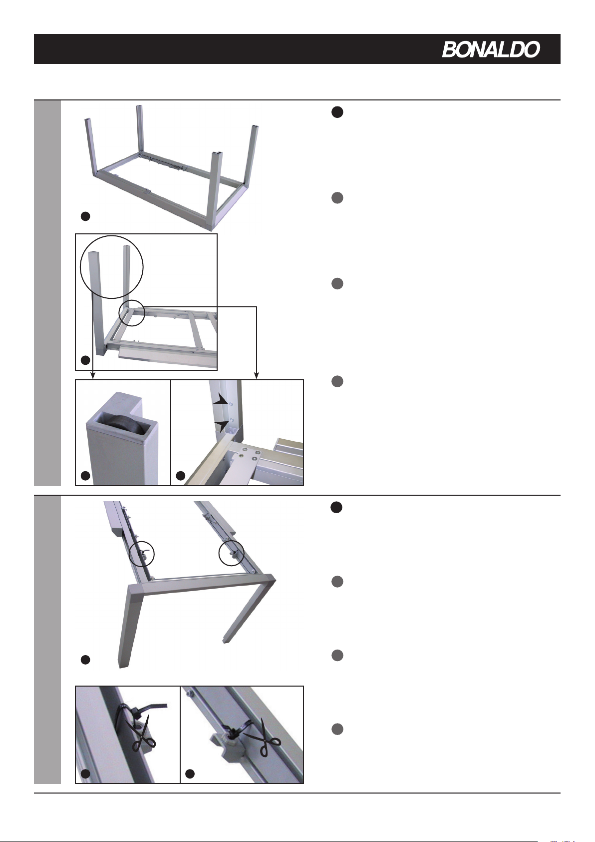
1

Other Bonaldo Indoor Furnishing manuals

Bonaldo BLOOM STORAGE UNIT User manual

Bonaldo

Bonaldo BLOOM STORAGE UNIT User manual

Bonaldo Giotto User manual

Bonaldo

Bonaldo Giotto User manual

Bonaldo Prora User manual

Bonaldo

Bonaldo Prora User manual

Bonaldo AMLET User manual

Bonaldo

Bonaldo AMLET User manual

Bonaldo BASKET AIR User manual

Bonaldo

Bonaldo BASKET AIR User manual

Bonaldo CAMPO User manual

Bonaldo

Bonaldo CAMPO User manual

Bonaldo CUFF Bed User manual

Bonaldo

Bonaldo CUFF Bed User manual

Bonaldo OWEN User manual

Bonaldo

Bonaldo OWEN User manual

Bonaldo Stealth User manual

Bonaldo

Bonaldo Stealth User manual

Bonaldo Menu Extending table User manual

Bonaldo

Bonaldo Menu Extending table User manual

Bonaldo CURLING User manual

Bonaldo

Bonaldo CURLING User manual

Bonaldo NARCISO User manual

Bonaldo

Bonaldo NARCISO User manual

Bonaldo Tracks User manual

Bonaldo

Bonaldo Tracks User manual

Bonaldo Thin User manual

Bonaldo

Bonaldo Thin User manual

Bonaldo Octa Dining Table User manual

Bonaldo

Bonaldo Octa Dining Table User manual

Bonaldo MELLOW User manual

Bonaldo

Bonaldo MELLOW User manual

Bonaldo ART WOOD User manual

Bonaldo

Bonaldo ART WOOD User manual

Bonaldo TRUE User manual

Bonaldo

Bonaldo TRUE User manual

Bonaldo DELTA User manual

Bonaldo

Bonaldo DELTA User manual

Bonaldo BLABLA User manual

Bonaldo

Bonaldo BLABLA User manual

Bonaldo Amond User manual

Bonaldo

Bonaldo Amond User manual

Bonaldo Youniverse User manual

Bonaldo

Bonaldo Youniverse User manual

Bonaldo GEOMETRIC TABLE User manual

Bonaldo

Bonaldo GEOMETRIC TABLE User manual

Bonaldo JOE User manual

Bonaldo

Bonaldo JOE User manual

Popular Indoor Furnishing manuals by other brands

Gude OFT 855 Translation of the original instructions

Gude

Gude OFT 855 Translation of the original instructions

Victor 8832 instructions

Victor

Victor 8832 instructions

Better Homes and Gardens Twin XL Deluxe Adjustable Bed Base owner's manual

Better Homes and Gardens

Better Homes and Gardens Twin XL Deluxe Adjustable Bed Base owner's manual

Rauch M2803 Assembly instructions

Rauch

Rauch M2803 Assembly instructions

Extremis EXTEMPORE PATCHWORK ASSEMBLY INSTRUCTIONS, HOW TO USE, USEFUL TIPS FOR KEEPING YOUR TOOL FOR TOGETHERNESS IN SHAPE

Extremis

Extremis EXTEMPORE PATCHWORK ASSEMBLY INSTRUCTIONS, HOW TO USE, USEFUL TIPS FOR KEEPING YOUR TOOL FOR TOGETHERNESS IN SHAPE

Mocka Kids Modern Easel Assembly instructions

Mocka

Mocka Kids Modern Easel Assembly instructions

Walker Edison REEH8GDW Assembly instructions

Walker Edison

Walker Edison REEH8GDW Assembly instructions

WIEMANN 991306 manual

WIEMANN

WIEMANN 991306 manual

JWA 70823 Assembly instruction

JWA

JWA 70823 Assembly instruction

CARRARO 1063 manual

CARRARO

CARRARO 1063 manual

Blanco BLANCOMEDALLION 157-014 Specification sheet

Blanco

Blanco BLANCOMEDALLION 157-014 Specification sheet

UNIPRODO UNI-PPG01 user manual

UNIPRODO

UNIPRODO UNI-PPG01 user manual

OSP Home Furnishings JASPER JAP9867 Assembly instructions

OSP Home Furnishings

OSP Home Furnishings JASPER JAP9867 Assembly instructions

Pressalit SELECT R4950 Operation and maintenance manual

Pressalit

Pressalit SELECT R4950 Operation and maintenance manual

LDI Spaces SAFCO Metro 3442 Assembly instructions

LDI Spaces

LDI Spaces SAFCO Metro 3442 Assembly instructions

Quadro Basic 2D Assembly instructions

Quadro

Quadro Basic 2D Assembly instructions

SAFAVIEH COUTURE Parker DSK6400 manual

SAFAVIEH COUTURE

SAFAVIEH COUTURE Parker DSK6400 manual

LUXE BIDET Sophea installation manual

LUXE BIDET

LUXE BIDET Sophea installation manual

manuals.online logo
manuals.online logoBrands
  • About & Mission
  • Contact us
  • Privacy Policy
  • Terms and Conditions

Copyright 2025 Manuals.Online. All Rights Reserved.