SKILTEC LUXAFLEX LUMINETTE Parts list manual

ISSUE DATE: FEBRUARY 2018 ORIGINATOR: SKILTEC
REPLACES ISSUE DATE: FEB 2018 APPROVED BY: S. GONZALEZ PAGE 1 OF 29
PRODUCT INFORMATION MANUAL
SECTION: 12B LUMINETTE PRIVACY SHEERS POWERVIEW MOTORISATION
LUMINETTE PRIVACY SHEERS
POWERVIEW MOTORISATION

ISSUE DATE: FEBRUARY 2018 ORIGINATOR: SKILTEC
REPLACES ISSUE DATE: FEB 2018 APPROVED BY: S. GONZALEZ PAGE 2 OF 29
PRODUCT INFORMATION MANUAL
SECTION: 12B LUMINETTE PRIVACY SHEERS POWERVIEW MOTORISATION
LUMINETTE®PRIVACY SHEERS
PowerView™Motorisation
Installation •Operation •Care
ISSUE DATE: FEBRUARY 2018 ORIGINATOR: SKILTEC
REPLACES ISSUE DATE: FEB 2018 APPROVED BY: S. GONZALEZ PAGE 3 OF 29
PRODUCT INFORMATION MANUAL
SECTION: 12B LUMINETTE PRIVACY SHEERS POWERVIEW MOTORISATION
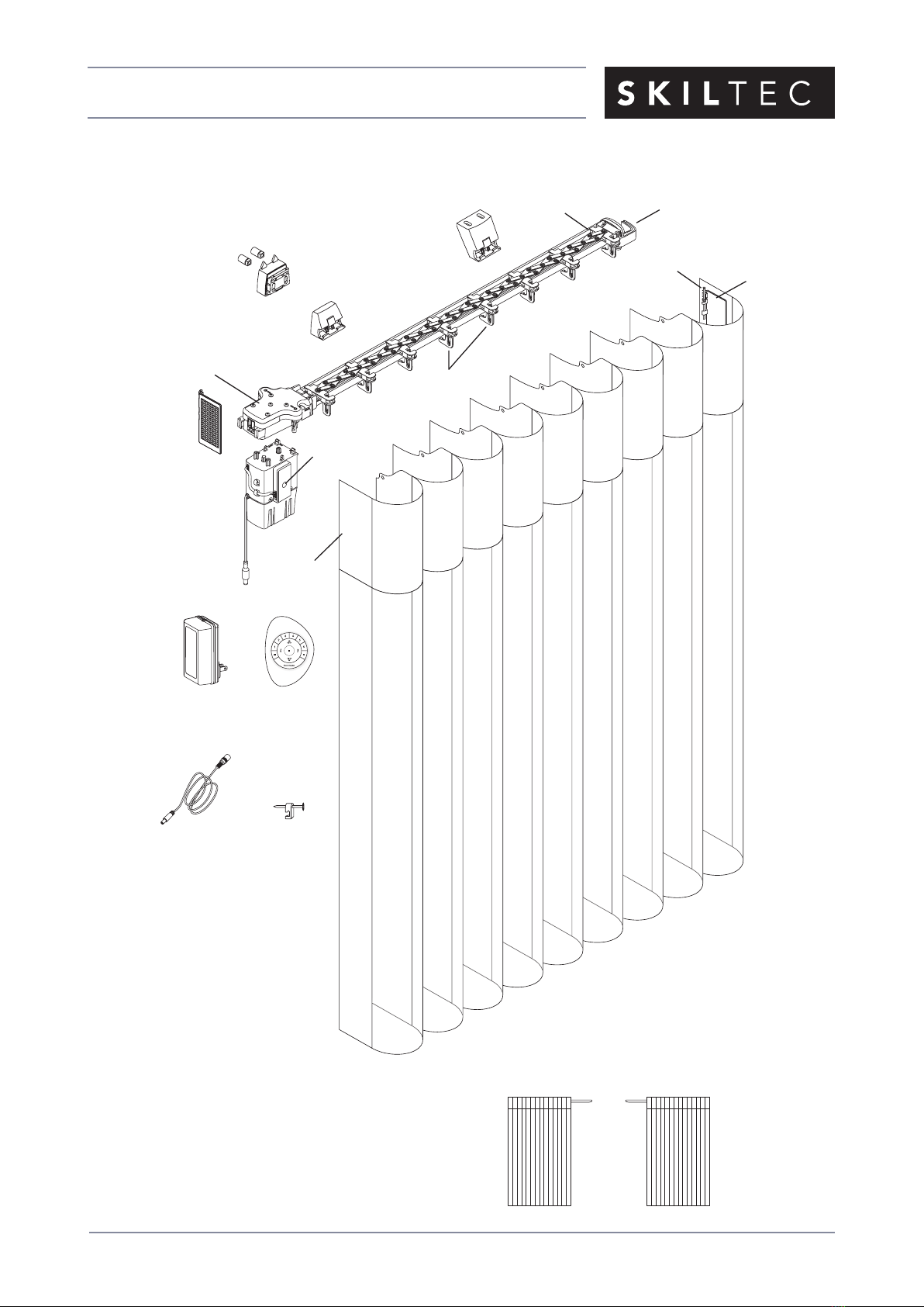
Product View
Left Stack Right Stack
SofTrak™
Headrail
Swivel
Plate
Rivet
Swivel
Arm
Left Stack Shown
Inside/Ceiling
Mount Bracket
Installation Bracket
Faceplate
DC Power
Supply
DC Power
Supply Cable
C-Clip
Modular
Motor
Assembly
Manual
Control
Button
PowerView
™
Remote
Drive Assembly
Spacer Block
with Bushings
Pinion
Clips
Swivel
Plate
End
Treatment
ISSUE DATE: FEBRUARY 2018 ORIGINATOR: SKILTEC
REPLACES ISSUE DATE: FEB 2018 APPROVED BY: S. GONZALEZ PAGE 4 OF 29
PRODUCT INFORMATION MANUAL
SECTION: 12B LUMINETTE PRIVACY SHEERS POWERVIEW MOTORISATION
Thank you for purchasing LUXAFLEX®LUMINETTE®Privacy Sheers with PowerView™Motorisation. With
proper installation, operation, and care, your new sheers will provide years of beauty and performance.
Please thoroughly review this instruction booklet and the packing list included with your order before
beginning the installation.
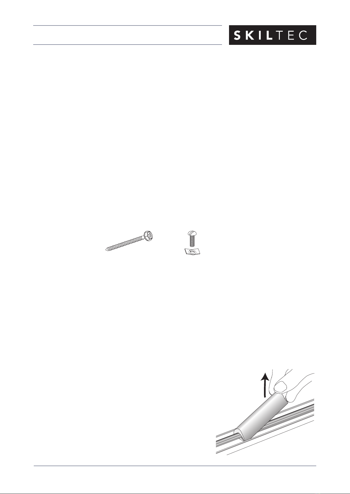
Tools and Fasteners Needed
■Flat blade and Phillips screwdrivers
■Measuring tape and pencil
■Power drill, 3mm drill bit,
and 6mm hex driver
In addition, you will need fasteners designed to work with your specific mounting surface(s).
■#6 Hex Head Screws (Provided). Two 38mm screws are provided per installation bracket.
■Speed Nuts and Screws (Provided). Extension brackets come with screws and speed nuts.
■Drywall Anchors (Not Provided). Use drywall anchors when mounting into drywall.
Unpack the Components
■Make sure you have clean hands or wear disposable gloves when handling Luminette fabric. To avoid
wrinkling the fabric, do not fold it or drape it over furniture.
■One or more fabric panels may be packaged in a carton.
■The fabric panels are rolled around a cardboard tube. Do not remove the protective wrapping until
starting the “Attach the Fabric Panel(s)” step on page 16.
■Remove the SofTrak™headrail system and installation hardware from inside the carton.
■Remove the foam supports from the tilt shaft inside the
headrail. Rotate the supports in either direction until they can
be pulled off.
IMPORTANT: With wider fabrics, the SofTrak headrail may
be shipped separately.
Remove
Foam Supports
■Level (laser level is recommended)
■Needlenose pliers
■Utility knife and scissors
Speed Nut
and Screw
(Two Provided with
Each Extension Bracket)
#6 x 38mm
Hex Head Screw
(Provided)

ISSUE DATE: FEBRUARY 2018 ORIGINATOR: SKILTEC
REPLACES ISSUE DATE: FEB 2018 APPROVED BY: S. GONZALEZ PAGE 5 OF 29
PRODUCT INFORMATION MANUAL
SECTION: 12B LUMINETTE PRIVACY SHEERS POWERVIEW MOTORISATION
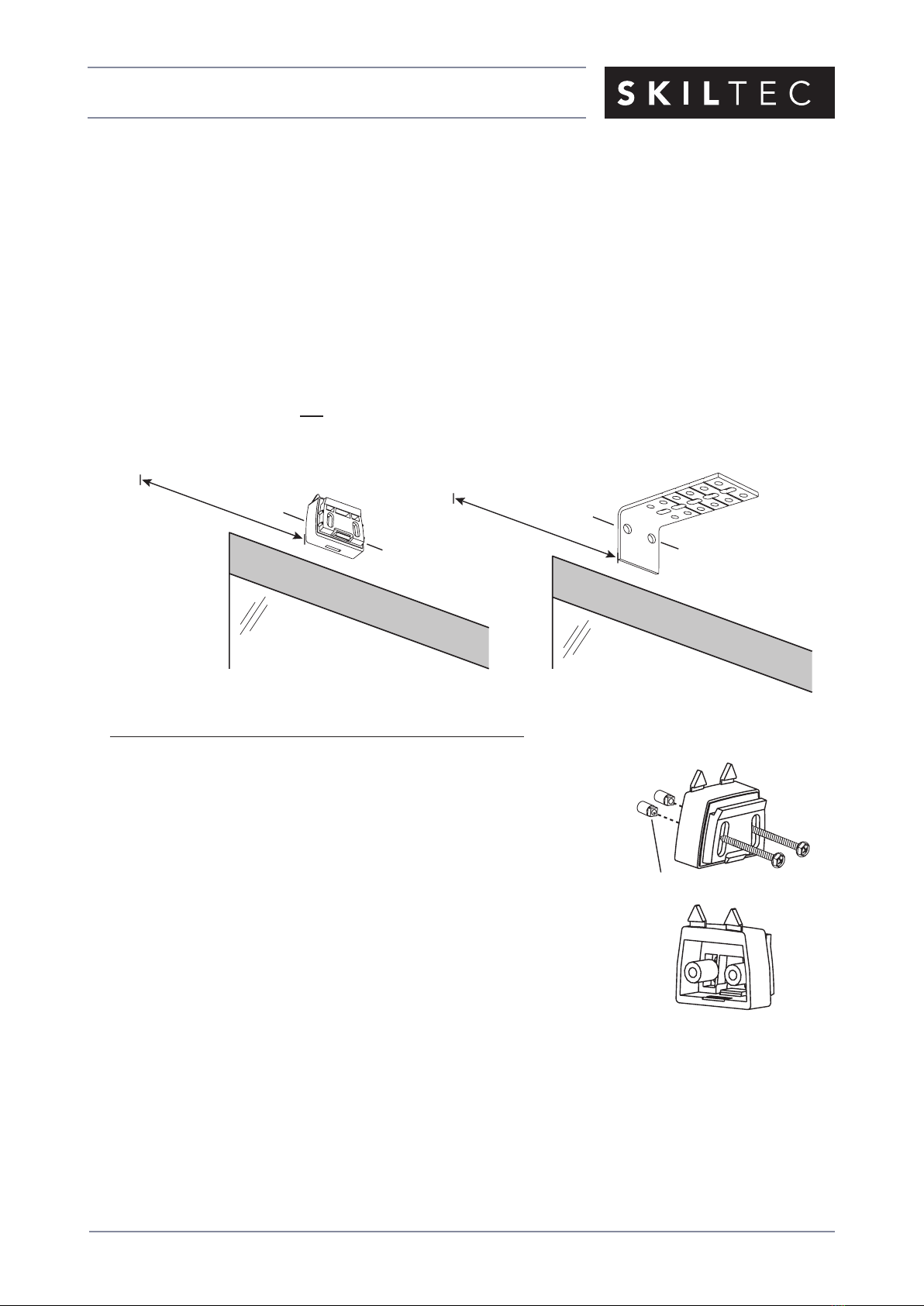
Mounting Types and Window Terminology
If the installation brackets are mounted correctly, the rest of the installation process follows easily. To
prepare for this important first step, review the mounting types and basic window terminology illustrated
below.
■For proper operation, the fabric must clear all obstructions, including window cranks, handles, and
moldings.
➤Replace protruding window cranks with T-cranks, as needed.
■Refer to the appropriate page below based on your order:
➤Reveal/Ceiling Fit — Page 4
➤Face Fit — Page 7
Collectively, the sill and
jambs are called the
“window casement.”
Molding (or Wall)
Head Jamb
Sill (or Floor)
Jamb Jamb
Reveal Fit
Sheer fits
within window
or door opening.
Face Fit
Sheer mounts
outside window
or door opening.
Recommended
Installation

ISSUE DATE: FEBRUARY 2018 ORIGINATOR: SKILTEC
REPLACES ISSUE DATE: FEB 2018 APPROVED BY: S. GONZALEZ PAGE 6 OF 29
PRODUCT INFORMATION MANUAL
SECTION: 12B LUMINETTE PRIVACY SHEERS POWERVIEW MOTORISATION
Mount the Installation Brackets — Reveal/Ceiling Fit
If you are mounting on corner or bay windows, refer to “Bracket Locations — Corner and Bay Windows” on
page 11 for specific bracket locations. Return to this page after identifying
the bracket locations.
■Your order will include the appropriate number of inside/ceiling mount installation brackets. The number
of installation brackets required varies with headrail width, as shown below.
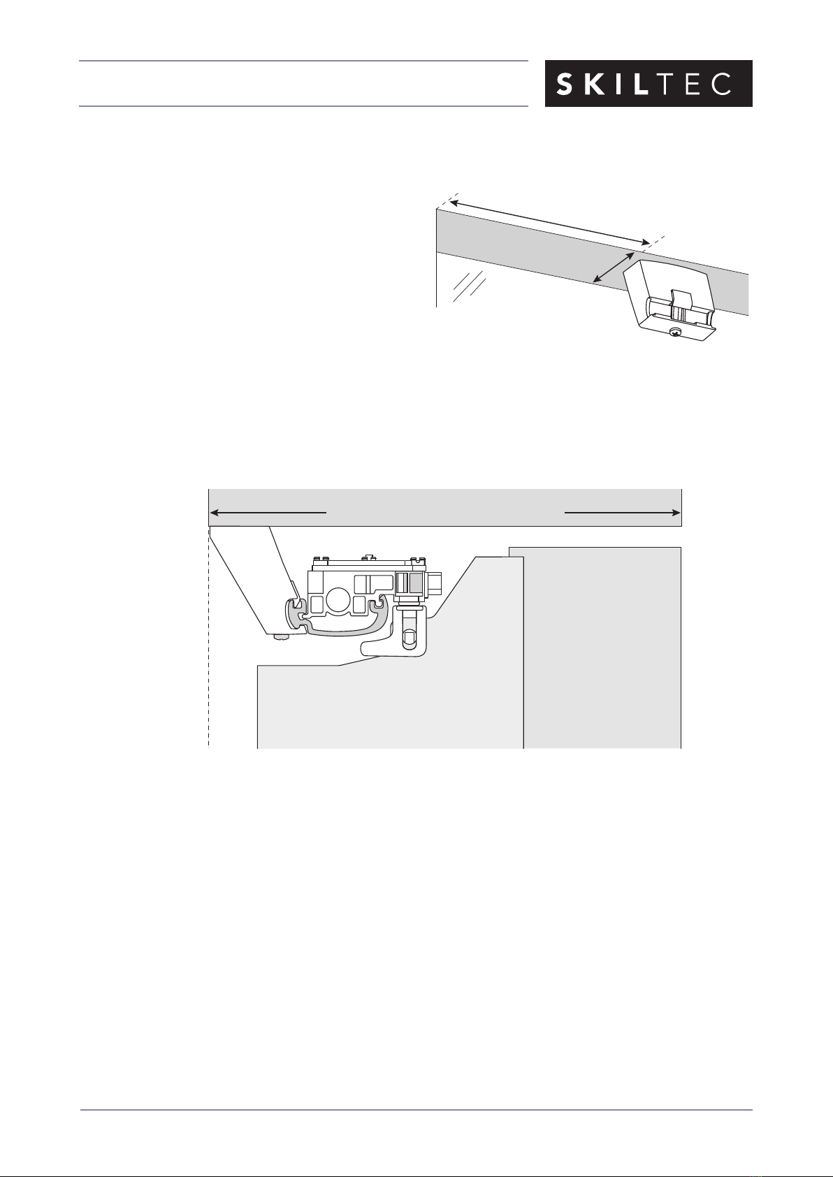
Measure and Mark Bracket Locations
■Mark 130mm from each jamb on the mounting surface.
➤If more than two installation brackets are required (see table above), mark the locations of additional
bracket(s) spaced evenly between the two end brackets.
CAUTION: Installation brackets should be fastened into wood whenever possible. Use drywall anchors
when mounting into drywall. When attaching brackets into drywall, additional brackets may be required to
keep the headrail level after the fabric is attached.
Inside/Ceiling Mount
Installation Bracket
Headrail
Width (mm)
Brackets Required
Up to 1016 2
1017 - 1778 3
1779 - 2438 4
2439 - 3937 6
3938 - 4875 8
Top View
Bracket
Jamb
Jamb
SofTrak™Headrail
Space EvenlySpace Evenly
130mm
16mm Gap Required
Motor
130mm
ISSUE DATE: FEBRUARY 2018 ORIGINATOR: SKILTEC
REPLACES ISSUE DATE: FEB 2018 APPROVED BY: S. GONZALEZ PAGE 7 OF 29
PRODUCT INFORMATION MANUAL
SECTION: 12B LUMINETTE PRIVACY SHEERS POWERVIEW MOTORISATION
■Mark where to drill holes for the screws.
IMPORTANT: The front edges of the brackets must align to each other.
➤Align the outside edge of the end brackets
on your marks, then mark each of the screw
holes. Center additional brackets on the marks
to mark their screw holes.
➤The minimum mounting depth required is
25mm.
➤To fully recess the fabric in the window
casement, the mounting depth required
is 160mm. See the illustration below.
Bracket Headrail
Stacked
Fabric
Vane
160mm Minimum Fully Recessed Depth
Reveal Fit
Fully Recessed Mounting Depth
Window
Side
25mm Minimum
130mm
ISSUE DATE: FEBRUARY 2018 ORIGINATOR: SKILTEC
REPLACES ISSUE DATE: FEB 2018 APPROVED BY: S. GONZALEZ PAGE 8 OF 29
PRODUCT INFORMATION MANUAL
SECTION: 12B LUMINETTE PRIVACY SHEERS POWERVIEW MOTORISATION
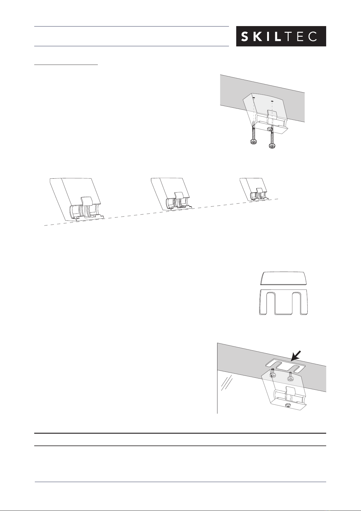
Mount the Brackets
■Drill the screw holes using a 3mm drill bit.
CAUTION: Use drywall anchors when mounting into
drywall.
■Attach the installation brackets using the screws provided.
IMPORTANT: For proper operation, the headrail must be mounted
level. Use a laser level to check that the installation brackets are
level and aligned. Shim the brackets if necessary. The brackets
may also need to be shimmed if the mounting surface is heavily
textured.
To Shim the Brackets:
■Snap off the top of the shim for use with inside/ceiling mount brackets.
■Use the shims, as needed, between the mounting
surface and the reveal/ceiling fit brackets.
Use a laser level as reference.
■To make further adjustments, you may add or remove shims by loosening
the installation bracket screws.
Proceed to “Install the SofTrak™Headrail” on page 23.
Level and
Aligned
Snap Off
Shim
Loosen
screws
to add or
remove shims.

ISSUE DATE: FEBRUARY 2018 ORIGINATOR: SKILTEC
REPLACES ISSUE DATE: FEB 2018 APPROVED BY: S. GONZALEZ PAGE 9 OF 29
PRODUCT INFORMATION MANUAL
SECTION: 12B LUMINETTE PRIVACY SHEERS POWERVIEW MOTORISATION
Mount the Installation Brackets — Face Fit
If you are mounting on corner or bay windows, refer to “Bracket Locations — Corner and Bay Windows” on
page 11 for specific bracket locations. Return to this page after identifying the bracket locations.
■Your order will include the appropriate number of installation bracket assemblies. The number of
assemblies required varies with headrail width, as shown below.
IMPORTANT: The spacer blocks have tabs that prevent the
brackets from being mounted too close to the ceiling. If the sheer
will not be mounted at ceiling level, the tabs can be removed.
Adding Clearance
■Use spacer blocks to add additional clearance. Spacer blocks add clearance in 13mm increments.
➤One spacer block is used with the faceplate for standard installation. Three additional spacer blocks
may be added for an extra 38mm clearance.
■Use optional extension brackets to add more clearance.
➤Extension brackets can provide up to 90mm clearance.
➤Indentations are stamped into the extension brackets between each set of holes. Using the
indentations as a guide, you may cut off any unneeded length before mounting the extension
brackets. Each two-hole section is 13mm length.
Headrail
Width (mm)
Bracket Assemblies
Required
Up to 1016 2
1017 - 1778 3
1779 - 2438 4
2439 - 3937 6
3938 - 4875 8
Removable
Tabs
Faceplate
Spacer
Block
Bushings
Outside Mount
Bracket Assembly
Extension
Bracket

ISSUE DATE: FEBRUARY 2018 ORIGINATOR: SKILTEC
REPLACES ISSUE DATE: FEB 2018 APPROVED BY: S. GONZALEZ PAGE 10 OF 29
PRODUCT INFORMATION MANUAL
SECTION: 12B LUMINETTE PRIVACY SHEERS POWERVIEW MOTORISATION
Measure and Mark Bracket Locations
■Position the SofTrak™headrail over the window or door opening at the ordered height, found on the
headrail label. Use a pencil to lightly mark each end of the headrail.
➤Alternatively, measure the width of the headrail and use that width to mark the headrail end points
over the opening.
IMPORTANT: Typically, split stack designs are centered over the opening. However, side stack designs
may be offset to one side if the fabric was intended to stack partially or completely off the window or
door opening. The intended stackback must be taken into account when marking the headrail end
points.
■Mark 130mm from each end of the headrail.
➤If more than two installation brackets are required (see table on previous page), mark the locations
of additional bracket(s) spaced evenly between the two end brackets.
CAUTION: Installation brackets should be fastened into wood whenever possible. Use drywall anchors
when mounting into drywall. When attaching brackets into drywall, additional brackets may be required to
keep the headrail level after the fabric is attached.
■Mark the bracket mounting height to allow proper floor clearance for the fabric when attached to the
headrail. This method provides a minimum of 13mm floor clearance.
➤Locate the ordered height on the headrail label.
➤Spacer Blocks: Measure the ordered height minus
6mm from the floor surface. Mark this height at each
bracket location.
➤Extension Brackets: Measure the ordered height plus
6mm from the floor surface.
Mark this height at each bracket location.
IMPORTANT: Mount the screws at the height indicated,
or higher for additional floor clearance. Be sure to clear
all floor obstructions such as carpet, vents, rugs, etc.
Floor Surface
Ordered
Height – 6mm
Ordered
Height + 6mm
Spacer
Block
Extension
Bracket
Headrail End Marks
Window Opening
Space Evenly Space Evenly
130mm 130mm
ISSUE DATE: FEBRUARY 2018 ORIGINATOR: SKILTEC
REPLACES ISSUE DATE: FEB 2018 APPROVED BY: S. GONZALEZ PAGE 11 OF 29
PRODUCT INFORMATION MANUAL
SECTION: 12B LUMINETTE PRIVACY SHEERS POWERVIEW MOTORISATION
■Mark where to drill holes for the installation screws.
➤A minimum of 30mm flat vertical surface is required for spacer block installation and
33mm flat vertical surface is required for installation with extension brackets.
➤Align the spacer blocks or extension brackets on your height marks.
➤Align the outside edge of the end spacer blocks or extension brackets on your bracket
location marks, then mark each of the screw holes. Center any additional brackets on
the bracket location marks to mark their screw holes.
CAUTION: The rear of the spacer blocks or extension brackets must be flush against a flat
mounting surface. Do not mount blocks/brackets oncurved molding.
Mount the Spacer Blocks or Extension Brackets
■Drill the screw holes using a 3mm drill bit.
CAUTION: Use drywall anchors when mounting into drywall.
■Attach the spacer blocks or extension brackets using the screws
provided.
➤For the spacer block installation, first insert the square end
of the bushings into the slots in the spacer block. Insert the
screws through bushings.
IMPORTANT: With spacer blocks, place the screws in the
middle of the slots to make aligning the brackets easier.
Bushings
Bushings Inserted
130mm
Headrail
End Mark
Headrail
End Mark
Screw
Height
Mark
Screw
Height
Mark
130mm

ISSUE DATE: FEBRUARY 2018 ORIGINATOR: SKILTEC
REPLACES ISSUE DATE: FEB 2018 APPROVED BY: S. GONZALEZ PAGE 12 OF 29
PRODUCT INFORMATION MANUAL
SECTION: 12B LUMINETTE PRIVACY SHEERS POWERVIEW MOTORISATION
➤For extension bracket installation, you may cut off any unneeded length (before mounting) at
indentations stamped into the brackets between each set of holes. Each two-hole section is 13mm
in length.
IMPORTANT: For proper operation, the SofTrak™headrail must be mounted level. Use a laser level
to check that the spacer blocks or extension brackets are level and aligned. Shim the brackets if
necessary. The brackets may also need to be shimmed if the mounting surface is heavily textured.
To Shim the Brackets:
➤Loosen the installation screws securing the spacer
block or extension bracket.
➤Insert one or more shims between the spacer block or
extension bracket and
the mounting surface. Tighten the installation screws.
Finish Bracket Assembly
Spacer Blocks
■Add any additional spacer blocks required.
IMPORTANT: A maximum of four spacer blocks can be used.
■Hook the top of the faceplate to the front spacer block and snap
it into place.
Level and Aligned
Level and Aligned
Loosen
Mounting
Screws
Insert
Shim(s)
1
2
1
2
To Shim
Installation Bracket
To Shim
Extension Bracket
Faceplate
ISSUE DATE: FEBRUARY 2018 ORIGINATOR: SKILTEC
REPLACES ISSUE DATE: FEB 2018 APPROVED BY: S. GONZALEZ PAGE 13 OF 29
PRODUCT INFORMATION MANUAL
SECTION: 12B LUMINETTE PRIVACY SHEERS POWERVIEW MOTORISATION
200mm
Brackets
130mm
200mm 130mm
Motor
Motor
75mm
Extension
Bracket
Cover
Extension
Bracket
Extension Bracket
Base Cover
Screws
Speed Nuts
Inside/Ceiling
Mount Bracket
Extension Brackets
■Slide the base covers onto each extension bracket.
■If necessary, use scissors to trim the flat bracket cover to length. Slide a cover onto
each bracket.
■Attach inside/ceiling mount installation brackets using the screws and speed nuts provided.
Proceed to “Install the SofTrak™Headrail” on page 23.
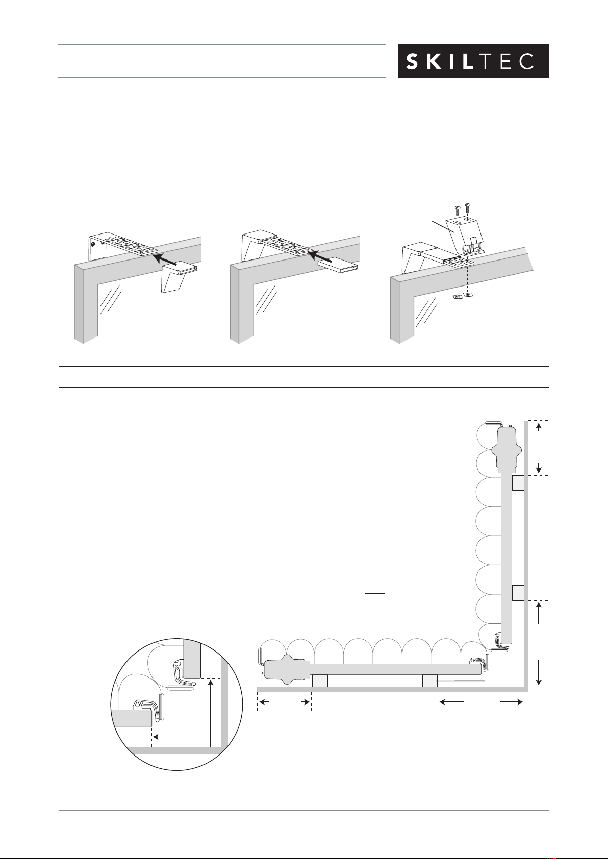
Bracket Locations — Corner and Bay Windows
■For bracket placement, mount the spacer blocks or inside/ceiling mount
brackets 200mm from the corner.
IMPORTANT: The ends of the headrails should be located 75mm from the
corner.
➤If additional spacer blocks or extension brackets are used,
the installation brackets must be further moved away from the corner by
the amount of added clearance.
■For bay windows, treat the center sheer as a corner system on both ends of
the headrail.

ISSUE DATE: FEBRUARY 2018 ORIGINATOR: SKILTEC
REPLACES ISSUE DATE: FEB 2018 APPROVED BY: S. GONZALEZ PAGE 14 OF 29
PRODUCT INFORMATION MANUAL
SECTION: 12B LUMINETTE PRIVACY SHEERS POWERVIEW MOTORISATION
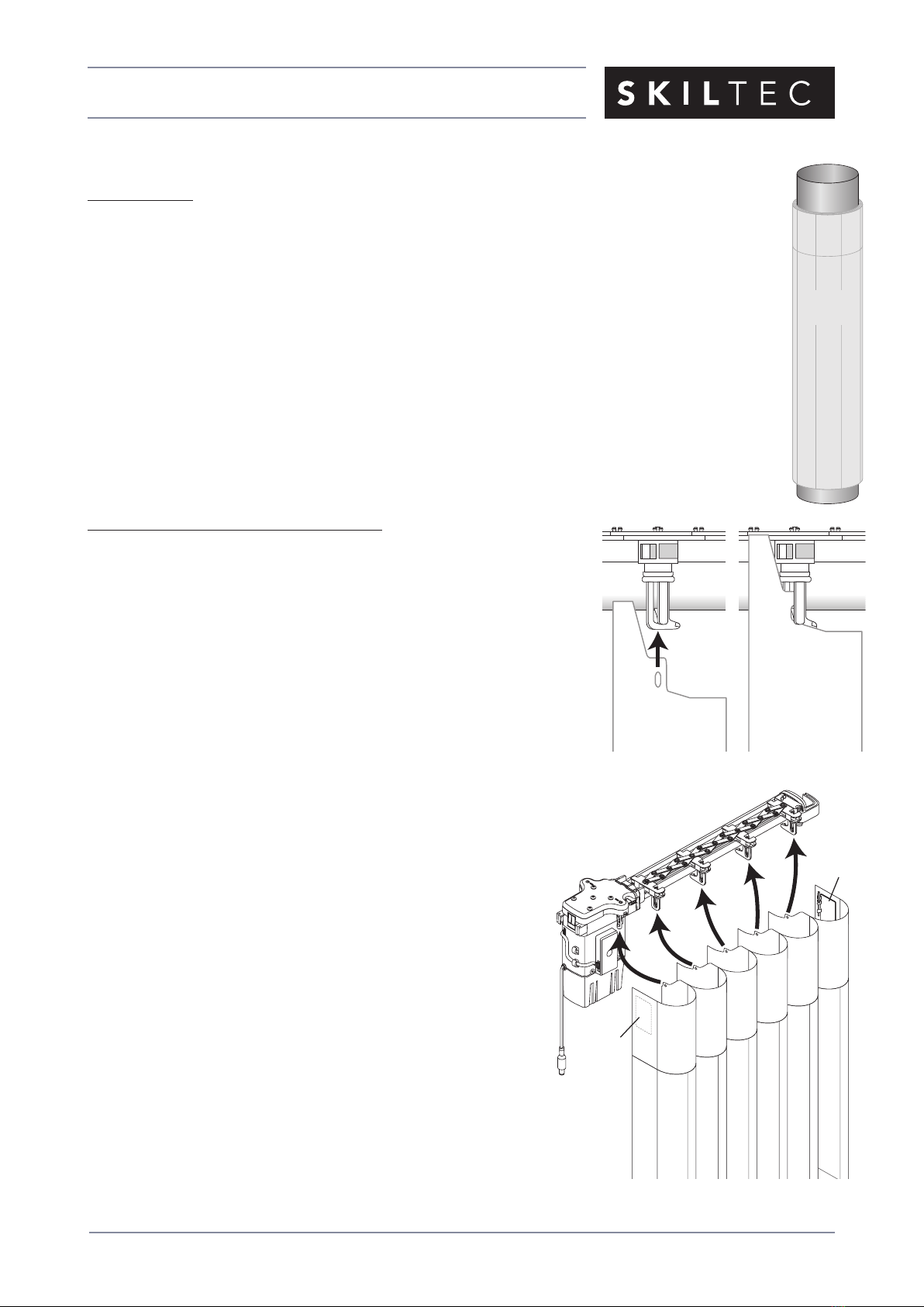
Install the SofTrak™Headrail
■Push up on the locking screws. This raises the locking tab and
makes the headrail easier to install.
■The grooves on the back of the headrail are designed to snap
into the locking tab on the faceplate and inside/ceiling mount
bracket.
➤Tilt the front of the headrail (the side with the pinion clips) up
so the top groove fits into the locking tab on each installation
bracket.
■With the top groove in place on all brackets, tilt
the headrail down so the bottom groove fits into
the bottom tabs on the installation brackets.
■Position/center the headrail and tighten the locking screws until
snug. Do not overtighten.
Reveal Fit and Wall-To-Wall Face Fit Installations
■After the SofTrak headrail is installed into the installation brackets, check the clearance at eachend and
make any necessary adjustments.
IMPORTANT: The recommended amount of clearance varies according to the control end and stack
design, as shown below.
Tilt Down
Pinion
Clip
Tighten
Tilt Up
Locking
Tab
SofTrak™
Headrail
Locking
Screw
Right Stack Design — Minimum Clearances
22mm
Non-Motor End
3mm
Left Stack Design — Minimum Clearances3mm
Non-Motor End
22mm
Motor End
Motor End

ISSUE DATE: FEBRUARY 2018 ORIGINATOR: SKILTEC
REPLACES ISSUE DATE: FEB 2018 APPROVED BY: S. GONZALEZ PAGE 15 OF 29
PRODUCT INFORMATION MANUAL
SECTION: 12B LUMINETTE PRIVACY SHEERS POWERVIEW MOTORISATION
Side-by-Side (Abutted) Installations (Simulated Split Stack)
A simulated split stack (the fabric opens in the center)
is two side stack systems installed with the non-control
ends side-by-side.
■Adjust the SofTrak™headrails according to the
illustration for proper swivel arm operation.
IMPORTANT: Be sure to measure the spacing from
end cap to end cap, not from the swivel arms.
Non-Control
End Cap
Non-Control
End Cap
38mm
Swivel
Plates
Swivel
Arm
Swivel
Arm
RTW
Swivel
Plates
RTW Not Recommended
Proper Installation
Simulated Split Stack
ISSUE DATE: FEBRUARY 2018 ORIGINATOR: SKILTEC
REPLACES ISSUE DATE: FEB 2018 APPROVED BY: S. GONZALEZ PAGE 16 OF 29
PRODUCT INFORMATION MANUAL
SECTION: 12B LUMINETTE PRIVACY SHEERS POWERVIEW MOTORISATION
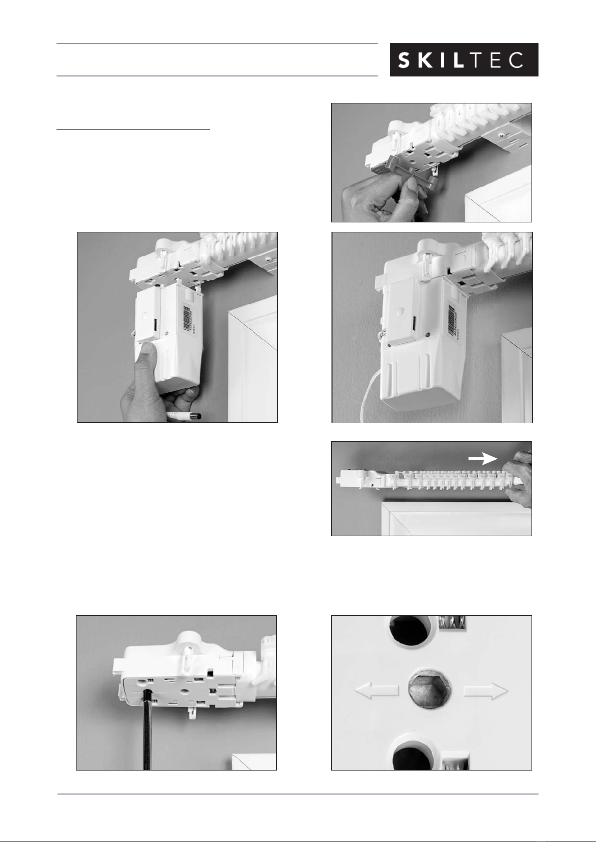
Connect PowerView™Components
Connect the Motor Assembly
■Remove the orange cover from the drive assembly, as
shown to the right.
■Align the pins with the holes in the drive assembly, as
shown below. Press the motor
up into the drive assembly until it clicks into place.
IMPORTANT: If snapping the motor onto
the drive assembly seems difficult, grasp
the lead carrier and pull the carriers slightly
away from the motor, as shown at right.
The motor should now snap in easily.
■If you remove the motor and need to reinstall it, check the drive assembly and make sure the tilt
gear aligns with the arrows.
➤If necessary, use a screwdriver to turn the tilt gear until it is aligned.
Aligned Tilt Gear
ISSUE DATE: FEBRUARY 2018 ORIGINATOR: SKILTEC
REPLACES ISSUE DATE: FEB 2018 APPROVED BY: S. GONZALEZ PAGE 17 OF 29
PRODUCT INFORMATION MANUAL
SECTION: 12B LUMINETTE PRIVACY SHEERS POWERVIEW MOTORISATION
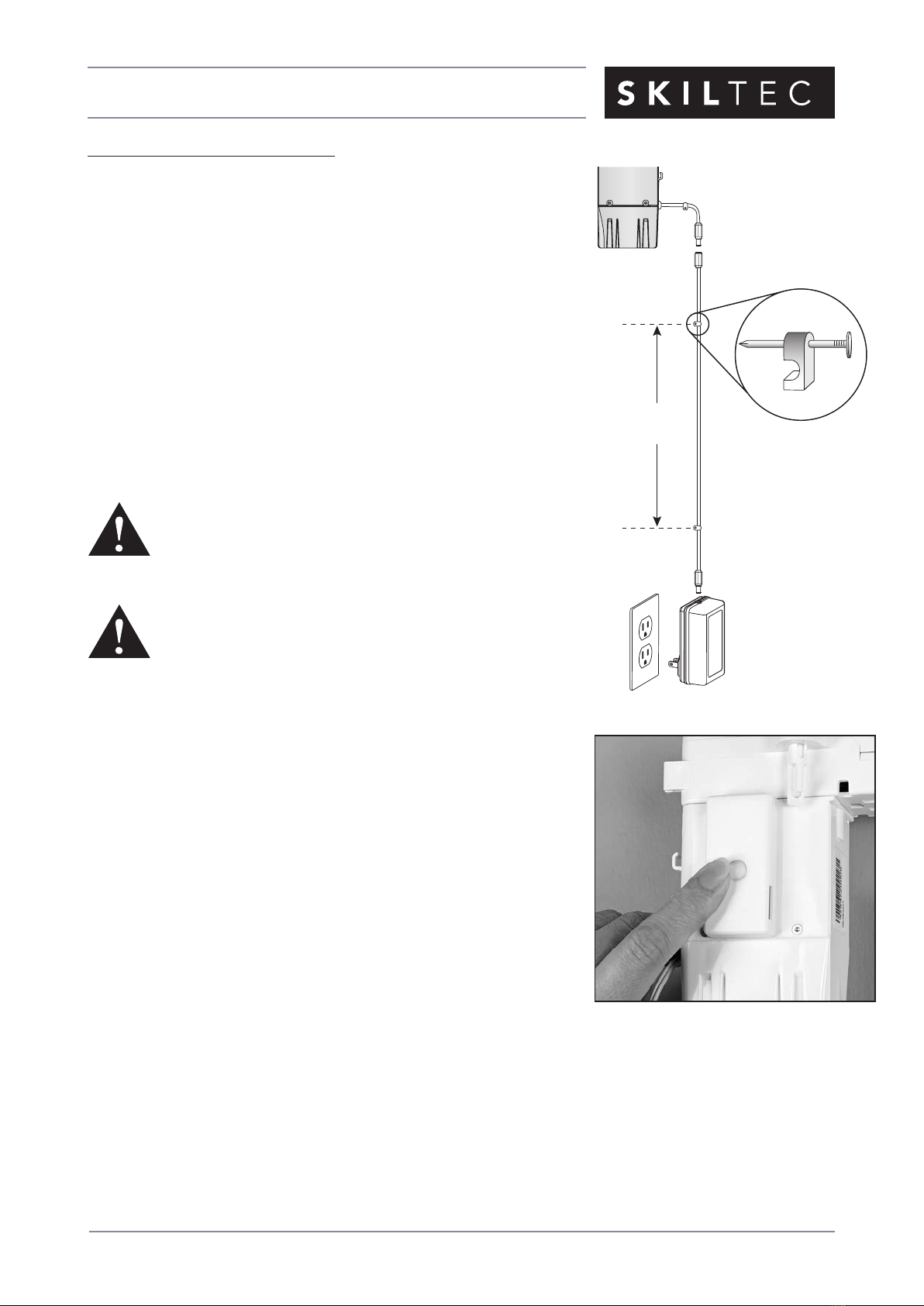
Connect the DC Power Supply
NOTE: When power is connected to the motor, a green LED inside
the manual control button housing will flash to indicate the sheer is
ready.
■Plug the power cable from the motor into the extensioncable.
■Plug the other end of the extension cable into the DC power
supply.
■Secure the extension cable using the C-clips provided. Hide the
cable behind the fabric, making sure it does not impede operation.
■Space the C-clips approximately 385mm apart along the
extension cable, as shown.
■Plug the DC power supply into the power source.
WARNING: Keep cables and small parts
out of the reach of children. They can wrap cables around
their necks and STRANGLE. They can also put small parts
in their mouths and CHOKE.
WARNING: Electric shock and/or afire hazard may occur
if not properlyinstalled.
385mm
Maximum
DC
Power
Supply
Wire Retainer
Extension Cable
Power Cable
Motor
Assembly
Test Headrail Operation
■Use the manual control button on the motor to test the operation of
the headrail, following the sequence below.
1. Press and release the button to traverse the carriers across the
full length of the headrail.
2. Press and release the button to fully rotate the pinion clips in one
direction.
3. Press and release the button to fully rotate the pinion clips in the
opposite direction.
4. Press and release the button to rotate the pinion clips to the
neutral (vanes open) position.
5. Press and release the button to traverse the carriers to the fully stacked position.
■Pressing the manual control button while the carriers are traversing or the pinion clips are
rotating will stop the action. The next button press will traverse the carriers or rotate the
pinion clips in the opposite direction.
Manual
Control
Button
ISSUE DATE: FEBRUARY 2018 ORIGINATOR: SKILTEC
REPLACES ISSUE DATE: FEB 2018 APPROVED BY: S. GONZALEZ PAGE 18 OF 29
PRODUCT INFORMATION MANUAL
SECTION: 12B LUMINETTE PRIVACY SHEERS POWERVIEW MOTORISATION
Attach the Fabric Panel(s)
Preparations
■If necessary, use the manual control button to traverse the fabric carriers to the fully stacked
position.
■Stand the tube on end on a clean surface with the valance at the top. Position the tube at the
end of the headrail where the fabric stacks.
■If the tube is too long to stand on end, carefully and safely use a utility knife to trim the tube
to an appropriate length. Do not unroll the fabric until you begin attaching the vanes to the
pinion clips.
CAUTION: Be very careful when trimming the tube to avoid damaging the fabric in any way.
■Remove the protective wrapping from the fabric.
Attach the Vanes to the Pinion Clips
■Unroll the fabric to gain enough slack to attach the first vane to the
pinion clip on the motor drive assembly.
■To attach vanes, insert the vane attachment hole into the clip until it
snaps securely in place.
➤Pull down gently on each vane to ensure that it is seated
properly.
■Unroll the fabric as you clip the rest of the vanes into the pinion
clips in sequence.
Be careful not to skip any pinion clips
orvanes.
Pinion
Clip
Installed
Vane
Tube
Fabric
Panel
STD R
Vane Attachment
Swivel
Plate
Swivel
Plate

ISSUE DATE: FEBRUARY 2018 ORIGINATOR: SKILTEC
REPLACES ISSUE DATE: FEB 2018 APPROVED BY: S. GONZALEZ PAGE 19 OF 29
PRODUCT INFORMATION MANUAL
SECTION: 12B LUMINETTE PRIVACY SHEERS POWERVIEW MOTORISATION
Attach Swivel Plates
■The end treatments on both ends of the sheer attached with
swivel plates.
➤Swivel plates are right- and left-specific, marked by an R
or an L. The swivel plates are packaged with the product’s
hardware.
■Snap the rivet on the swivel plate into the front clip on the
control end cap. Swivel plates attached on the left will have STD
Lstamped on the top. Swivel plates attached on the right will
have STD R on the top.
■Snap the rivet on the other swivel plate onto the swivel arm (side stack) or into the front clip on the
non-control end cap (split stack). Swivel plates attached on the right will have STD R stamped on the
top. Swivel plates attached on the left will have STD L on the top.
STD RSTD L
Swivel Plate
Side Stack
Swivel Arm
Rivet
Swivel Plate
Split Stack
Rivet
Front Clip
Non-Control
End Cap
STD R
STD R
Rivet
STD L

ISSUE DATE: FEBRUARY 2018 ORIGINATOR: SKILTEC
REPLACES ISSUE DATE: FEB 2018 APPROVED BY: S. GONZALEZ PAGE 20 OF 29
PRODUCT INFORMATION MANUAL
SECTION: 12B LUMINETTE PRIVACY SHEERS POWERVIEW MOTORISATION
Attach the End Treatment(s) to the Swivel Plate(s)
■Hold the end treatment near the swivel plate at a height where
the end vanes hang straight and the top of the end treatment is
approximately 3mm above the top of the swivel plate.
■Attach the end treatment by pressing it onto the
swivel plate.
■If the end treatment is not hanging straight, separate the swivel
plate from the end treatment and reposition it. Separate the swivel
plate by pulling up on the end treatment while holding the swivel
plate in place.
■Re-attach the end treatment. Repeat the adjustment as necessary.
Swivel
Plate
Table of contents
Other SKILTEC Window Blind manuals


Popular Window Blind manuals by other brands


Griesser
Griesser Alucolor 25 operating instructions

Graywind
Graywind 58433 instruction manual

rollease acmeda
rollease acmeda KUMO Assembly manual

Hella
Hella TOP MINI plus screen protect Operating guidelines

Guthrie Douglas
Guthrie Douglas TESS 140 instruction manual

Tommee Tippee
Tommee Tippee sleeptight quick start guide