Skov DA 150B Manual

2022.05.05 • 604164
DA 150B Pad Cooling
Technical User Guide


DA 150B Pad Cooling
Product and Documentation Changes
SKOV A/S reserves the right to change this manual and the product described herein without further notice. In
case of doubt, please contact SKOV A/S.
Date of change appears from the front and the back page.
In case of misoperation or improper use, cooling systems can result in production loss or cause
loss of lives among animals.
SKOV A/S recommends that cooling systems be mounted, operated and serviced only by trained
staff and that a separate emergency opening unit and an alarm system be installed as well as
maintained and tested at regular intervals, according to SKOV A/S’s terms and conditions of
sale and delivery.
Qualified personnel must perform installation, service and fault-finding of all electrical
equipment in accordance with the applicable national and international standard EN 60204-1 and
any other EU standards that are applicable in Europe.
The installation of a power supply isolator is required for each motor and power supply to
facilitate voltage-free work on the electrical equipment. SKOV A/S does not supply the power
supply isolator.
Note
•All rights reserved. No part of this manual may be reproduced in any manner whatsoever without
the express written permission of SKOV A/S in each case.
•SKOV A/S has made reasonable efforts to ensure the accuracy of the information contained in this
manual. Should any mistakes or imprecise information occur in spite of this, SKOV A/S would
appreciate being notified thereof.
•Irrespective of the above, SKOV A/S shall not have any liability with respect to loss or damage
caused or alleged to be caused by reliance on any information contained herein.
•Copyright by SKOV A/S.

4 Technical User Guide
DA 150B Pad Cooling
1Product Description................................................................................................. 6
1.1 Overview of DA 150B Pad Cooling System ....................................................................... 6
1.1.1 DA 150B Pad Cooling, Supply Unit.........................................................................................................7
1.1.2 DA 150B Pad Cooling, Middle/End Kit 6 m .............................................................................................8
1.1.3 DA 150B Pad Cooling, Middle/End Kit 3 m .............................................................................................9
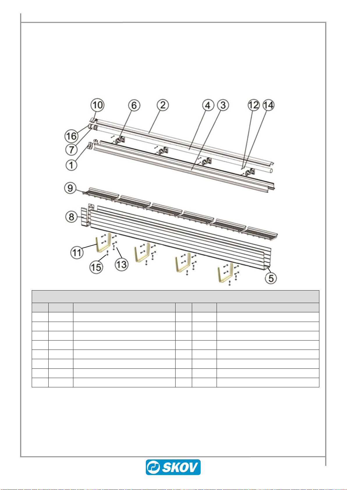
1.1.4 DA 150B Pad Cooling, Extension 3m ...................................................................................................10
1.1.5 DA 150B Pad Cooling, Extension 2x3m................................................................................................11
1.1.6 DA 150B Pad Cooling 3 m Corner Connection .....................................................................................12
1.1.7 DA 150B Pad Cooling Corner Connection Kit.......................................................................................13
1.1.8 Pad ........................................................................................................................................................14
1.1.9 DA 150B Pump......................................................................................................................................14
1.1.10 DA 150B / DA 100 B Pad cooling check valve kit .................................................................................14
1.1.11 DA 150B Glue Kit - max. 12 m ..............................................................................................................15
2General Information................................................................................................16
2.1 Recommended Tools........................................................................................................ 16
2.2 Safety Guidelines - Intended Use..................................................................................... 18
2.3 Electrical System .............................................................................................................. 18
2.3.1 Circuit Diagram1x230 V ........................................................................................................................19
2.3.2 Circuit Diagram 3x230 V .......................................................................................................................19
3Mounting Guide ......................................................................................................20
3.1 Total Height of Pad Cooling System, Wall....................................................................... 20
3.2 Total Height of Pad Cooling System, Floor ..................................................................... 21
3.3 Opening for Pad Cooling .................................................................................................. 21
3.4 Bracket for Water Gutter................................................................................................... 22
3.4.1 Even number of extension sets .............................................................................................................22
3.4.2 Uneven number of extension sets.........................................................................................................22
3.5 Water Gutter ...................................................................................................................... 23
3.6 Top Bracket ....................................................................................................................... 24
3.7 Water Distribution Pipe..................................................................................................... 25
3.7.1 Deflector ................................................................................................................................................26
3.8 Inner Pad Guide ................................................................................................................ 27
3.9 Piping................................................................................................................................. 27
3.9.1 Supply unit.............................................................................................................................................28
3.9.2 Check Valve ..........................................................................................................................................28
3.9.3 Water Distribution..................................................................................................................................29
3.9.4 Prior start up ..........................................................................................................................................30
3.9.1 End cover with overflow protection .......................................................................................................30
3.10 Glue Instruction ................................................................................................................ 31
3.10.1 Glued Connections................................................................................................................................31
3.10.2 Safety Advice –Tangit PVC-U/C ..........................................................................................................32
3.10.3 Glue Water Gutter and Pipes ................................................................................................................33
3.11 Covers and ........................................................................................................................ 35
3.12 Bleed off Valve .................................................................................................................. 36
3.13 Pad ..................................................................................................................................... 37
3.14 Outer Pad Guide................................................................................................................ 37
3.15 Pointing sealing edge ....................................................................................................... 38
3.15.1 Flat and smooth wall .............................................................................................................................38
3.15.2 Uneven and not smooth wall .................................................................................................................38
4Maintenance Instructions.......................................................................................39

Technical User Guide 5
DA 150B Pad Cooling
4.1 Maintenance Routines ...................................................................................................... 39
5Technical Data ........................................................................................................43
5.1 Load on the Bracket.......................................................................................................... 43
5.2 Water Quality..................................................................................................................... 43

6 Technical User Guide
DA 150B Pad Cooling
1 Product Description
DA 150B pad cooling is applied for cooling of large air quantities in tunnel ventilation systems. Fresh air is
directed through pads by means of negative pressure in the house. When cooling is required, the pads are kept
moist with water, which circulates from lower gutter to the top of the pad. Pad cooling can be mounted on the
wall or on the floor.
Figure 1: Pad cooling overview
1.1 Overview of DA 150B Pad Cooling System
The “DA 150B pad cool basic 6 m”or “DA 150B pad cool basic 3 m” are complete 6 m or 3 m pad cooling
systems and consist of a supply unit, a middle element with end kit and a check valve.
The following part numbers are available:
•437773 DA 150B pad cool basic 6m 1x230V 50Hz
•437774 DA 150B pad cool basic 6m 1x230V 60Hz
•437783 DA 150B pad cool basic 6m ex pump
•437778 DA 150B pad cool basic 3m 1x230V 50Hz
•437759 DA 150B pad cool basic 6m 3x230/400V60Hz
If a DA 150B pad cooling system longer than 6 m or 3 m is required use part number:
•437828 DA 150B pad cool extension 3m
•437824 DA 150B pad cool extension 2x3 m
The total length of a DA 150B pad cooling system must not exceed 24 metres.

Technical User Guide 7
DA 150B Pad Cooling
1.1.1 DA 150B Pad Cooling, Supply Unit
DA 150B pad cooling, supply unit is included in the “DA 150B pad cool basic 6 m”and “DA 150B pad cool
basic 3m”.
The following part numbers are available:
•437770 DA 150B pad cool supply 1x230V 50Hz
•437771 DA 150B pad cool supply 1x230V 60Hz
•437784 DA 150B pad cool supply ex pump
•437779 DA 150B pad cool supply 3m 1x230V 50Hz
•437716 DA 150B pad cool supply 3x230/400V 60Hz
437770/437771/437779/437716/437784*
DA 150B pad cool supply 1x230V, 3x230/400V, 50/60Hz
Pos.
Number
Description
Pos.
Number
Description
1*
1
DA 150B pump 1x230V 60Hz
DA 150B pump 1x230V 50Hz
DA 150B pump 1x230V 50Hz 350W
DA 150B pump 3x230/400V 60Hz
7
1
Motor cover
2
1
T- glue coupler 2"
8
1
Transition piece (glued)
3
4
Elbow glue coupler 2"
9
1
Bleed off valve (glued)
4
1
Ball Valve 2"
10
1
Tube ¾" black
5
6
Washer A 6.4
11
1
Clamp ¾"
6
6
Fasteners 6x40
*Note –the supply unit 437784 is without pump.

8 Technical User Guide
DA 150B Pad Cooling
1.1.2 DA 150B Pad Cooling, Middle/End Kit 6 m
DA 150B pad cooling, middle/end kit is included in the “DA 150B pad cooling, basic 6 m”.
The following part number is available:
•437775 DA 150B pad cool middle/end kit 6m
437775 DA 150B pad cool middle/end kit 6m
Pos.
Number
Description
Pos.
Number
Description
1
4
Pad guide coupler cpl.
12
26
Fasteners 5x50
2
2
Deflector 3000 hinged
13
28
Fasteners 6x40
3
4
Pad guide 3000
14
26
Washer A 5.3
4
2
Water distribution pipe 2" 4/100-3000
15
28
Washer A 6.4
5
1
Water gutter 2500
16
4
Clamp for pipe connector 50-70 mm
5
1
Water gutter 3000
17
2
Pad end-cover 6"
6
8
Top bracket hinged 150 mm Pad
18
2
End cover deflector 6" hinged
7
2
Pipe connector
19
2
End cover for water gutter
8
3
Joint for water gutter
20
2
Sealing cap 2"
9
11
Pad Support 150/500
21
2
Flat gasket 59 x 75 x 2
10
2
Deflector coupler hinged
22
2
Transition piece 2"
11
7
Bracket for water gutter
23
1
Water pipe 2" 2500 mm

Technical User Guide 9
DA 150B Pad Cooling
1.1.3 DA 150B Pad Cooling, Middle/End Kit 3 m
DA 150B pad cooling, middle/end kit is included in the “DA 150B pad cooling, basic 3 m”.
The following part number is available:
•437780 DA 150B pad cool middle/end kit 3m
437780 DA 150B pad cool middle/end kit 3m
Pos.
Number
Description
Pos.
Number
Description
1
2
Pad guide coupler cpl.
13
16
Fasteners 6x40
2
1
Deflector 3000 hinged
14
8
Washer A 5.3
3
2
Pad guide 3000
15
16
Washer A 6.4
4
1
Water distribution pipe 2" 4/100-3000
16
2
Clamp for pipe connector 50-70 mm
5
1
Water gutter 3000
17
2
Pad end-cover 6"
6
4
Top bracket hinged 150 mm Pad
18
2
End cover deflector 6" hinged
7
1
Pipe connector
19
2
End cover for water gutter
8
2
Joint for water gutter
20
2
Sealing cap 2"
9
6
Pad Support 150/500
21
2
Flat gasket 59 x 75 x 2
10
1
Deflector coupler hinged
22
2
Transition piece 2"
11
4
Bracket for water gutter
23
1
Water pipe 2" 2500 mm
12
8
Fasteners 5x50

10 Technical User Guide
DA 150B Pad Cooling
1.1.4 DA 150B Pad Cooling, Extension 3m
DA 150B pad cooling, extension 3 m is used if a pad cooling system longer than 6 meter is required.
The total length of a pad cooling system can be up to 24 metres.
The following part number is available:
•437828 DA 150B pad cool extension 3m
437828 DA 150B pad cool extension 3m (Middle Element)
Pos.
Number
Description
Pos.
Number
Description
1
2
Pad guide coupler cpl.
9
6
Pad Support 150/500
2
1
Deflector 3000 hinged
10
1
Deflector coupler hinged
3
2
Pad guide 3000
11
4
Bracket for water gutter
4
1
Water distribution pipe 2" 4/100-3000
12
8
Fasteners 5x50
5
1
Water gutter 3000
13
16
Fasteners 6x40
6
4
Top bracket hinged 150 mm Pad
14
8
Washer A 5.3
7
1
Pipe connector
15
16
Washer A 6.4
8
1
Joint for water gutter
16
2
Clamp for pipe connector 50-70 mm

Technical User Guide 11
DA 150B Pad Cooling
1.1.5 DA 150B Pad Cooling, Extension 2x3m
DA 150B pad cooling, extension 2x3 m is used if a pad cooling system longer than 6 meter is required.
The total length of a pad cooling system can be up to 24 metres.
The following part number is available:
•437824 DA 150B pad cool extension 2x3 m
437824 DA 150B pad cool extension 2x3m (Middle Element)
Pos.
Number
Description
Pos.
Number
Description
1
4
Pad guide coupler cpl.
9
12
Pad Support 150/500
2
2
Deflector 3000 hinged
10
2
Deflector coupler hinged
3
4
Pad guide 3000
11
8
Bracket for water gutter
4
2
Water distribution pipe 2" 4/100-3000
12
16
Fasteners 5x50
5
2
Water gutter 3000
13
32
Fasteners 6x40
6
8
Top bracket hinged 150 mm Pad
14
16
Washer A 5.3
7
2
Pipe connector
15
32
Washer A 6.4
8
2
Joint for water gutter
16
4
Clamp for pipe connector 50-70 mm

12 Technical User Guide
DA 150B Pad Cooling
1.1.6 DA 150B Pad Cooling 3 m Corner Connection
DA 150B pad cooling 3 m corner connection is used if a pad cooling system must be mounted around a corner
of the building. With the corner connection, it is also possible to have a distance between the basic system and
the corner connection.
Maximum length of the pad system after the corner is 12 m.
The total length of a pad cooling system can be up to 24 metres.
The following part number is available:
•437824 DA 150B pad cool extension 2x3m
•437828 DA 150B pad cool extension 3m
437709 DA 150B pad cool 3m corner connection
Pos.
Number
Description
Pos.
Number
Description
1
1
Deflector 3000 hinged
9
1
Pad end-cover 6"
2
2
Pad guide 3000
10
2
End cover deflector 6" hinged
3
1
Water distribution pipe 2" 4/100-3000
11
2
End cover for water gutter
4
1
Water gutter 3000
12
2
Sealing cap 2"
5
4
Top bracket hinged 150 mm Pad
13
2
Flat gasket 59 x 75 x 2
6
1
Joint for water gutter
14
2
Transition piece 2"
7
6
Pad Support 150/500
-
-
Screw set
8
4
Bracket for water gutter
-
-
Small parts kit

Technical User Guide 13
DA 150B Pad Cooling
1.1.7 DA 150B Pad Cooling Corner Connection Kit
DA 150B pad cooling corner connection kit is used for connecting the DA 150B pad cooling 3 m corner
connection and extensions up to 12 m after a corner.
Maximum length from the corner is 2.5 m in both directions.
The following part number is available:
•437895 DA 150B pad cool corner connection kit V2
437895 DA 150B pad cool corner connection kit V2
Pos.
Number
Description
Pos.
Number
Description
1
2
Flat gasket 59 x 75 x 2
24
Washer V2A 6.4/DIN 9021
2
2
Flat nut 2"
24
Fasteners 6 x 40 V2A
3
3
Glue elbow 2"
8
12
Top bracket 150 mm pad
4
6
PVC pipe 2" x 2500 mm
9
9
Pipe connector
5
2
Transition piece 2"
10
18
Clamp for pipe connector 50-70 mm

14 Technical User Guide
DA 150B Pad Cooling
1.1.8 Pad
Pad
Pos.
Number
Item no.
Description
1
1
437313
Pad 150x600x1500 green stripe 45/15
1
1
437314
Pad 150x600x1800 green stripe 45/15
1
1
437315
Pad 150x600x2000 green stripe 45/15
2
1
437256F
Pad 150x600x1200 45/15 H
2
1
437255F
Pad 150x600x1500 45/15 H
2
1
437251F
Pad 150x600x1800 45/15 H
2
1
437250F
Pad 150x600x2000 45/15 H
3
1
437272
Pad 150x600x1200 45/15 S
3
1
437269
Pad 150x600x1500 45/15 S
3
1
437270
Pad 150x600x1800 45/15 S
3
1
437271
Pad 150x600x2000 45/15 S
4
1
437287
Pad 150x600x1500 45/15 black coated S
4
1
437288
Pad 150x600x1800 45/15 black coated S
4
1
437289
Pad 150x600x2000 45/15 black coated S
5
1
437277
Pad 150x600x1500 45/45 S
5
1
437278
Pad 150x600x1800 45/45 S
5
1
437279
Pad 150x600x2000 45/45 S
6
1
437274
Pad PP150-3 150x600x1500
6
1
437275
Pad PP150-3 150x600x1800
6
1
437276
Pad PP150-3 150x600x2000
1.1.9 DA 150B Pump
DA 150B pump
Item no.
Description
437371
DA 150B pump 1x230V 50Hz
437370
DA 150B pump 1x230V 60Hz
437375
DA 150B pump 1x230V 50Hz 350W
437374
DA 150B pump 3x230/400V 60Hz
1.1.10 DA 150B / DA 100 B Pad cooling check valve kit
Pad cooling check valve kit
Item no.
Description
437947
DA 100B/150B check valve kit
1
2
3
4
5
6

Technical User Guide 15
DA 150B Pad Cooling
1.1.11 DA 150B Glue Kit - max. 12 m
437584 DA 150B Glue Kit - max. 12 m
Pos.
Number
Item no.
Description
1
1
530187
PVC-U glue Tangit 500g
2
1
530181
PVC-U cleaning fluid Tangit 1000ml
3
1
530003
Brush
4
4
530186
PVC-U glue Tangit 125 g paste tube
-
1
604170
Safety advice –Tangit PVC-U/C
1
4
2
3

16 Technical User Guide
DA 150B Pad Cooling
2 General Information
2.1 Recommended Tools
Below is a list of tools required for installation of your SKOV pad cooling system.
Item.
Description
Electrical Jig saw
Blades for cutting steel
Blades for cutting wood
Angle Grinder
With grinder disk for Steel/Iron
Impact drill for cement/concrete work
With various sized bits for drilling
Step Ladder that can reach all the way up to ceiling
Hand Saw
Cordless Battery Drill with spare batteries
With various Metric sized bits for screws
With various Metric sized socket (must have 8/10/13mm)
With various Metric sized bits for drilling steel/wood
Spirit Level (1 meter in length)
Tape measure/measure tools

Technical User Guide 17
DA 150B Pad Cooling
Item.
Description
Chalk string
Hammer
Screwdriver set
Pliers Wrench
Vise-Grip
Knife/Cutter
Marking Pencil
Spanner/Wrench set in Metric measurement
Adjustable spanner 10”
Ratchet Tie Down 20meters
Hole Saw 76 mm
Market Pen

18 Technical User Guide
DA 150B Pad Cooling
2.2 Safety Guidelines - Intended Use
These Operating Instructions include the most important information in connection with operating the pad
cooling system in a safe manner.
The relevant guidelines for the prevention of accidents as well as other generally recognised
technical safety and medical regulations for the workplace must be observed.
Check that the safety and functional equipment works safely and correctly:
•prior to start-up
•at appropriate intervals
•after modifications or maintenance.
The specifications outlined by the water and energy utility companies must also be observed.
The system is exclusively intended for cooling/air-conditioning. Usage for other purposes is not intended, like
e.g. pumping other liquids than water. The manufacturer/supplier is not responsible for damage resulting from
this. The user is solely responsible for the use.
To the intended use also belongs the attention of the manual and the adherence to of the maintenance
conditions.
2.3 Electrical System
The installation, service and troubleshooting in connection with electrical equipment must be
carried out by specialists in accordance with applicable national rules - in Europe in accordance
with EN 60204-1 and other applicable EU rules.
The installation of a supply isolator is required for each motor and power supply, so
maintenance of electrical equipment can be carried out in a dead environment. Supply isolator is
not supplied by SKOV A/S.
Mount the pump according to the supplier instruction manual.
The pump must be shielded from direct sunlight (50°C).
All tasks extending beyond the framework of system maintenance may only be carried out by qualified
personnel.
Always isolate the power supply when working on the device and secure against unauthorised reactivation by
another person.
Examine electrical cables for visible damage prior to commissioning.
Replace any damaged lines before putting the device into operation.
Damaged or destroyed plug devices must be replaced by a qualified electrician.
Covering electrical components can give rise to heat concentration with high temperatures which can in turn
destroy the equipment and cause fires.

Technical User Guide 19
DA 150B Pad Cooling
2.3.1 Circuit Diagram1x230 V
2.3.2 Circuit Diagram 3x230 V

20 Technical User Guide
DA 150B Pad Cooling
3 Mounting Guide
3.1 Total Height of Pad Cooling System, Wall
Overview of the total height of a wall-mounted pad cooling system.
A= Wall opening = D minus 115 mm
B= Measure from the lower edge of the
top
bracket to the top of the pad support.
1540 mm
1840 mm
2040 mm
C= Wall
D= Height of pads:
1500 mm
1800 mm
2000 mm
E= Bracket for water gutter
F= Water gutter and bracket (340 mm)
G= Substructure, concrete, wood or steel
(optional)
H= Full height of system, L1/L2 + A + F
J= The opening in the wall should have a
frame made of a water-resistant
material. The frame is not supplied by
SKOV A/S.
Important: The frame must be
smooth, in level and able to hold the
weight of the pad cooling system, see
section 5.1 and 3.15.
L1= 170 mm
L2= 320 mm
Figure 2: Total height –wall-mounted
Table of contents
Other Skov Accessories manuals