manuals.online logo
Brands
  1. Home
  2. •
  3. Brands
  4. •
  5. AMX
  6. •
  7. Control Panel
  8. •
  9. AMX Precis User manual

AMX Precis User manual

Quick Start Guide
AutoPatch Precis Remote X/Y Control Panel
Overview
The Precis Remote X/Y Control Panel is available in two configurations: 8x4 or 12x8,
each with or without digital volume control. For complete documentation, see the AMX
AutoPatch Software & Documentation CD or visit www.amx.com.
General Specifications
Installation
ESD Warning: Avoid ESD (Electrostatic Discharge) damage to
sensitive components; be sure you and the equipment are properly
grounded before touching any internal materials.
Rack Mounting
Precis Remote panels are designed to fit in a standard EIA 19 in. (48.26 cm) rack.
To install the Precis Remote panel in a rack:
1. Place panel in a rack and secure with front-mounting screws.
Connecting Remote Control Panel to an Enclosure
Communication Cable Requirements
• Two-conductor, 20 AWG, 7/28 strand cable with a drain wire or shield, such as
Alpha 2412C (customer supplied)
• Max. length of cable: 1640 ft. (500 m) total, including linked panels
To connect link cables:
1. Attach the two wires of the AutoPatch pigtail (included) to the communication
cable (customer supplied).
2. On the rear of the panel, plug the AutoPatch pigtail into either Comm Link
connector (FIG. 3).
3. On router’s CPU, unplug the XNNet connector (for connector location, see
router’s documentation).
4. Loosen the two outer screws on the connector.
5. Insert the two comm cable wires from the panel into two outer slots of the XNNet
connector, leaving center slot empty. Either wire goes in either outside slot.
6. Tighten screws and plug connector back into CPU.
Linking Multiple Panels
Precis Remote panels can be linked together in a daisy chain to create multiple control
points for a single system. XNNet link cables can be attached to either Comm Link.
The total distance of the cable runs cannot exceed 1640 ft. (500 m).
On large control networks, the last linked control panel may require termination with a
120 ohm resistor on the unused link connector. For termination information, see the
control panel instruction manual.
Applying Power
Power Requirements
Important: The AutoPatch transformer (optional) can only be used with the
+7 to +12 VDC connector.
For other power sources:
•+7 to +12 connector – acceptable power is +7 to +12 VDC with at least 500 mA
•+5 VDC connectors – acceptable power is +5 VDC with at least 500 mA
• Always use a UL approved power source. Check the power source’s
documentation for information specific to that power source
To apply power to the panel using the AutoPatch wall transformer:
1. Unplug the +7 to +12 VDC power connector on rear of panel.
2. Loosen the two outer screws and insert the power cable wires (FIG. 4). The side
of the wire with the white stripe is positive; the other side ground.
3. Tighten both screws and plug the connector back into the panel.
4. Plug the wall transformer into the power source.
Note: After applying power, check the Power LED on the front of the panel. If it is not
illuminated, check the power link on the rear of the panel.
Completing the Installation
We recommend completing the installation by executing a test switch routing Input 1 to
Output 2.
To execute a test switch:
1. Press the Cancel Key to clear the panel for switching.
2. Press the All Level Key.
The All Level Key illuminates.
3. Press Source Key 1.
Source Key 1 blinks.
4. Press Destination Key 2.
When Destination Key 2 illuminates, the switch is successful.
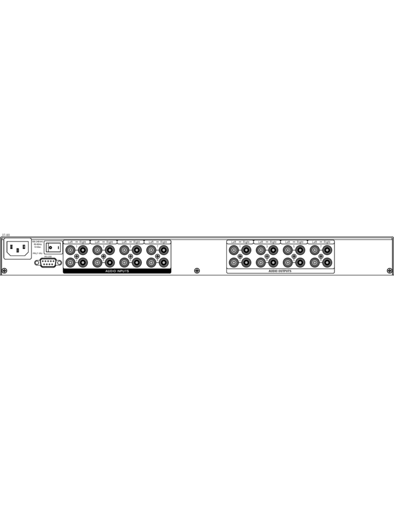
FIG. 1 Precis Remote X/Y Control Panel rear view
Specifications
Approvals CE
Cable for
XNNet Communications Two-conductor, 20 AWG, 7/28 strand cable with drain wire
or shield (such as Alpha 2412C)
Distance 1312 ft. (400 m) between remote and switcher
Distance 1640 ft. (500 m) total for linking purposes
Power +7 VDC to +12 VDC @ >500 mA
Or
+5 VDC @ >500 mA
Operational Temperature 32° - 110° F (0° - 43° C)
Humidity 0 to 90% non-condensing
Dimensions 1.64 in. (4.17 cm) depth
18.92 in. (48.06 cm) width with mounting ears
5.2 in. (13.21 cm) height, 3 RU
Weight Approximately 2 lb. (0.91 kg) per panel
FIG. 2 Secure panel to rack
Comm Link connectors
+7 to +12 VDC power connector +5 VDC power connectors
FIG. 3 Comm Link connector & wiring
FIG. 4 Remove power connector, wire, and replace
AutoPatch pigtail (included)
Comm cable (customer supplied)
Use either connector
(400 m)
Up to 1312 ft.
Positive
Ground
+7 to +12 VDC connector
Comm cable
For full warranty information, refer to the AMX AutoPatch Instruction Manual(s) associated with your Product(s).
7/07
©2007 AMX. All rights reserved. AMX and the AMX logo are registered trademarks of AMX.
AMX reserves the right to alter specifications without notice at any time.
3000 RESEARCH DRIVE, RICHARDSON, TX 75082 • 800.222.0193 • fax 469.624.7153 • technical support 800.932.6993 • www.amx.com
93-900-879 REV: A
Operation
Keys & Functions
•Macro Key – places the panel in Macro mode for executing local presets
•Lock Key – locks and unlocks panel operations (password required)
•Status Key – places the panel in Status mode
•Cancel Key – cancels an incomplete command and clears panel for
switching
•Level Keys – activates levels for switches or status inquiries; also used
to enter macros and password
•Source Keys – select a source (input) on specified level; also used to
enter macros
•Destination Keys – select a destination (output) on specified level; also
used to enter macros
A Precis Remote Panel operates in three standard modes: Switch (default), Status
and Macro. Use Switch mode to execute switches, Status mode to verify signal
status, and Macromode to execute macros (local presets). An additional mode, Lock
mode, enables the panel to be locked. An optional fifth mode, Volume Adjust, is also
available on some panels.
Switch mode is the default mode. It can be accessed at any time by pressing the
Cancel Key.
Executing / Disconnecting Switches
Note: When executing or disconnecting switches, check the Comm LED on the
control panel front to make sure it blinks. If the LED does not blink, check the Comm
Link connection on the rear of the control panel and the connection at the enclosure.
Before executing or disconnecting a switch, make sure the panel is cleared for
switching by pressing the Cancel Key (all lights on the panel turn off).
To execute a switch:
Note: You may select the destination(s) before selecting the source. Destinations
can receive signals from only one source at a time.
1. Press a Level Key to select a level.
(If no level is selected, the system defaults to “All Level” state,
Audio-follow-Video).
The Level Key illuminates.
2. Press a Source Key to select a source.
The Source Key flashes.
Any destinations already routed to that source illuminate after a slight delay.
3. Press a Destination Key(s) to select a destination(s).
The Destination Key illuminates.
To disconnect a switch:
Important: Disconnecting a source (input) disconnects all destinations (outputs)
receiving that signal.
1. Press a Level Key to select a level.
(If no level is selected, the system defaults to “All Level” state,
Audio-follow-Video).
The Level Key illuminates.
2. Select a Source Key.
The Source Key flashes and destinations routed to that source signal
illuminate after a slight delay.
3. Select an illuminated Destination Key.
The light turns off, and that destination (output) is disconnected.
Or
1. Press a Level Key to select a level.
(If no level is selected, the system defaults to “All Level” state
(Audio-follow-Video).
The Level Key illuminates.
2. Select a Destination Key.
The Source Key for the source routed to that destination illuminates.
3. Select the illuminated Source Key.
The light turns off, and that source (input) is disconnected from all destinations
(outputs).
Verifying Signal Status
To verify signal status:
1. Press the Status Key to put the panel in Status mode.
The Status Key illuminates and all other lights turn off.
2. Press a Level Key to select a level.
(If no level is selected, the system defaults to “All Level” state,
Audio-follow-Video).
The Level Key illuminates.
3. Press a source (input) or destination (output) key.
The pressed key illuminates.
When verifying a source (input), all the destinations (outputs) receiving a signal
from that input illuminate. If no destination (output) keys illuminate, the signal is
not routed or is not available on that level.
Or
When verifying a destination (output), the source (input) key illuminates,
showing the source routed to the destination being verified. If no source key
illuminates, the signal is not routed or is not available on that level.
4. Press the Cancel Key to clear the panel for further switching.
The Status, Source, and Destination Keys turn offf.
Audio Adjustments (Optional)
If the system is equipped with Volume Control, it also supports Input Gain Control.
When the volume is lower than -30 dB, an increase or decrease of 1 dB occurs each
time the Up Arrow Key or the Down Arrow Key is pressed and released. When the
volume is higher (louder) than -30 dB, the incremental change is 0.5 dB.
Important: Input Gain Control adjustments can be made in the same manner as
Volume Adjustments using the input (source) keys instead of the output (destination)
keys. We strongly recommend input gain adjustments be made only by a qualified
installer or dealer.
Volume Keys (optional)
•Volume Adjust (Status) Key – places panel in Volume Adjust mode
(hold key down until it flashes)
•Up Arrow (Macro) Key – increases volume while in Volume Adjust mode
•Down Arrow (Lock) Key – decreases volume while in Volume Adjust
mode
To adjust volume:
1. Press the Cancel Key to clear panel for changing modes.
2. Press and hold the Volume Adjust Key until it illuminates and then flashes.
The panel is in Volume Adjust mode.
3. Press a destination key to select the output that requires audio adjustment.
The destination key illuminates, along with the Up Arrow and
Down Arrow Keys.
4. Increase audio by pressing and releasing the Up Arrow Key.
Decrease audio by pressing and releasing the Down Arrow Key.
The pressed key flashes and then stays illuminated.
5. Repeat Step 4 until the desired volume level is reached.
6. Select another destination to adjust.
Or
Press the Cancel Key to clear the panel for further switching.
Note: Pressing the Cancel Key does not cancel any of the volume adjustments that
were just entered.
Additional Information Covered in the Precis Remote X/Y
Control Panel Instruction Manual
See the instruction manual on the CD or at www.amx.com for the following:
• Executing (pre-defined) local presets / macros
• Linking control panels
• Locking / unlocking the panel
• Setting a password
FIG. 5 Front view of a 12x8 Precis Remote with volume control
Level Keys Source Keys
Destination Keys
Cancel Key
Status Key
Macro Key Lock Key
Power & Comm Indicators
FIG. 6 Volume Adjust Keys
Volume
Adjust
Up Arrow
Down Arrow
Volume Adjust
(Macro) Key
(Lock) Key
(Status) Key
Other manuals for Precis

3

This manual suits for next models

2

Other AMX Control Panel manuals

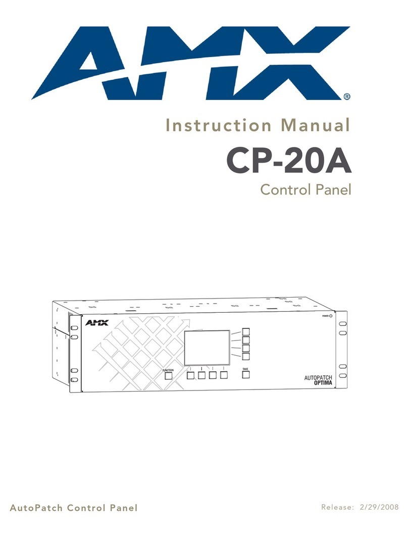
AMX AutoPatch CP-20A User manual

AMX

AMX AutoPatch CP-20A User manual

AMX Precis DSP Guide

AMX

AMX Precis DSP Guide

AMX AutoPatch CP-15 User manual

AMX

AMX AutoPatch CP-15 User manual

AMX CP-3017-TR-US User manual

AMX

AMX CP-3017-TR-US User manual

AMX Precis Original operating instructions

AMX

AMX Precis Original operating instructions

AMX Modero MXT-2000XL-PAN User manual

AMX

AMX Modero MXT-2000XL-PAN User manual

AMX Novara CP2000 Series User manual

AMX

AMX Novara CP2000 Series User manual

AMX Modero X MXT-700 Parts list manual

AMX

AMX Modero X MXT-700 Parts list manual

AMX AutoPatch CP-10 User manual

AMX

AMX AutoPatch CP-10 User manual

AMX AutoPatch CP-20A User manual

AMX

AMX AutoPatch CP-20A User manual

AMX AutoPatch CP-15 User manual

AMX

AMX AutoPatch CP-15 User manual

AMX AXU-SPPlus Guide

AMX

AMX AXU-SPPlus Guide

AMX AutoPatch CP-10 User manual

AMX

AMX AutoPatch CP-10 User manual

AMX ProLink PRO-DP8 User manual

AMX

AMX ProLink PRO-DP8 User manual

AMX Modero Viewpoint MVP-5200i User manual

AMX

AMX Modero Viewpoint MVP-5200i User manual

Popular Control Panel manuals by other brands

GSi TopDry Terminal 24 Operation manual

GSi

GSi TopDry Terminal 24 Operation manual

GREER Company Insight Calibration and Troubleshooting Manual

GREER Company

GREER Company Insight Calibration and Troubleshooting Manual

BSS Audio Soundweb London BLU-3 installation guide

BSS Audio

BSS Audio Soundweb London BLU-3 installation guide

Seav LG 2035 Compact quick start guide

Seav

Seav LG 2035 Compact quick start guide

DSC PowerSeries PC1616 installation guide

DSC

DSC PowerSeries PC1616 installation guide

Duevi CE 60-3 GSM Installer manual

Duevi

Duevi CE 60-3 GSM Installer manual

Honeywell NOTIFIER NFW-100X operating instructions

Honeywell

Honeywell NOTIFIER NFW-100X operating instructions

IDTECK iTDC Quick installation guide

IDTECK

IDTECK iTDC Quick installation guide

AIR-TRANSFER AT25 user manual

AIR-TRANSFER

AIR-TRANSFER AT25 user manual

Sony CCP-9000A-C Operation manual

Sony

Sony CCP-9000A-C Operation manual

Vimar ELVOX 13C5 Installer's guide

Vimar

Vimar ELVOX 13C5 Installer's guide

Johnson Controls IFC-200 operating instructions

Johnson Controls

Johnson Controls IFC-200 operating instructions

GARDTEC 800 User instructions

GARDTEC

GARDTEC 800 User instructions

Bosch AMAX panel 2000 ICP-AMAX-P installation manual

Bosch

Bosch AMAX panel 2000 ICP-AMAX-P installation manual

Sony MKS-8010A Operation manual

Sony

Sony MKS-8010A Operation manual

Lippert Components LCI Level-Up owner's manual

Lippert Components

Lippert Components LCI Level-Up owner's manual

XPower MULTI 1 Instruction and installation manual

XPower

XPower MULTI 1 Instruction and installation manual

mr. steam TEMPO/PLUS owner's manual

mr. steam

mr. steam TEMPO/PLUS owner's manual

manuals.online logo
manuals.online logoBrands
  • About & Mission
  • Contact us
  • Privacy Policy
  • Terms and Conditions

Copyright 2025 Manuals.Online. All Rights Reserved.