manuals.online logo
Brands
  1. Home
  2. •
  3. Brands
  4. •
  5. SKYDANCE
  6. •
  7. Media Converter
  8. •
  9. SKYDANCE D5 User manual

SKYDANCE D5 User manual

● 5 channels constant voltage output, Max. 6A current per channel, up to 720W output power.
● Master & decoder mode, RDM function.
● Easy operation with OLED display and 3 buttons.
● 1/2/3/4/5 channel decoding mode selectable.
● PWM frequency 250/500/2000/8000Hz selectable.
● 16bit (65536 levels) /8bit (256 levels) grey level selectable.
● Output dimming curve gamma value 0.1-9.9 selectable.
● Stand-alone RGB mode and 5 channel dimmer mode selectable,
work as DMX master(8 bit) to control other decoders.
● Built-in 25 RGB programs, speed and brightness adjustable.
● Support 3 kinds of DMX ports: Green terminal(amplify output), XLR3 and RJ45 port.
● Comply with the DMX512 standard protocols.
● Over-heat / Over-load / Short circuit protection, recover automatically.
● With fast self-testing function.
Output type Constant voltage
Output power 5 x (72-144)W
Output voltage 5 x (12-24)VDC
Output current 5CH,6A/CH
Input voltage 12-24VDC
Input current 30.5A
Technical Parameters
Input and Output
Operation temperature
Case temperature (Max.)
Environment
IP rating IP20
Ta: -30
O
C ~ +55
O
C
T c: +85
O
C
Model No.: D5
Features
RDM/Stand-alone function/8 bit or 16bit decode/Four PWM frequency/Multiple dimming curve/OLED display
Safety and EMC
EMC standard (EMC)
Certification CE,EMC,LVD
Safety standard(LVD)
EN55032:2015,
EN61000-3-2:2014,
EN61000-3-2:2013,
EN55024 :2010/A1:2015
5 Channel Constant Voltage DMX512 & RDM Decoder / Master
LVD
EN 61347-1:2015
EN 61347-2-11:2015
Warranty and Protection
5 years
Protection
Reverse Polarity
Over-heat
Over-load
Short circuit
Warranty
User Manual Ver 1.0.2 Page 1
www.iskydance.com
DMX input/output +
DMX input/output -
Mechanical Structures and Installations
Wiring Diagram
Power Input -
Power Input +
Output Red LED -
Output Green LED -
Output Blue LED -
Output White 1LED -
Installation rack
Output LED +
GND
Setting keyDigital display
DMX AMP output +
DMX AMP output -
RJ45 DMX signalXLR3 male DMX signal
XLR3 female DMX signal
Note:
1. Connecting with green terminal(DMX AMP) or an extra amplifier will be needed when more than 32 decoders
are connected, or use overlong signal line, signal amplification should not be more than 5 times continuously.
2. If the recoil effect occurs because of longer signal line or bad line quality, please try to connect 0.25W
90-120Ω terminal resistor at the end of each DMX signal line.
Uout=12- 24VDC
Iout=5CH×6 A
Pout=5×(72-144)W
Uin=12-2 4VDC
Iin=Max 3 0A
INPUT
12-24VD C
M
<
DMX IN/OUT
DMX decoder mode: 1-5CH, 8bit / 16bit
DMX master mode: 5CH Dimmer / RGB controller
DMXsignal amplify
Output PWM frequency: 250Hz, 500Hz, 2KHz, 8KHz
Output dimming curve: Gamma 0.1-9.9
Protection: Short circuit, Over current, Over heat
5CH DMX 512 & R DM Decoder / M ast er
1 2 3
4
5
R G B W1 W2
<
Temp Range:
-30℃-+55℃
Quick s elf -testing :
Long pr ess M &> key for 3s
170.00 mm
80.00 mm
39.50 mm
86.00 mm
GND
Output White 2 LED -
Uout=12- 24VDC
Iout=5CH×6 A
Pout=5×(72-144)W
Uin=12-2 4VDC
Iin=Max 3 0A
INPUT
12-24VD C
M
<
DMX IN/OUT
DMX decoder mode: 1-5CH, 8bit / 16bit
DMX master mode: 5CH Dimmer / RGB controller
DMXsignal amplify
Output PWM frequency: 250Hz, 500Hz, 2KHz, 8KHz
Output dimming curve: Gamma 0.1-9.9
Protection: Short circuit, Over current, Over heat
5CH DMX 512 & R DM Decoder / M ast er
1 2 3
4
5
R G B W1 W2
<
Temp Range:
-30℃-+55℃
Quick s elf -testing :
Long pr ess M &> key for 3s
DMX
Master
AC100-240V Power Supply
12-24VDC
Constant Voltage
RGB+CCT LED strip
WW
CW
DMX Decoder
Addrs:001 5CH
PwmHz:Std 8bit
Curve:Standard
DMX Decoder
Addrs:001 5CH
PwmHz:Std 8bit
Curve:Standard
D5 5 Channel Constant Voltage DMX512 & RDM Decoder / Master
User Manual Ver 1.0.2 Page 2
www.iskydance.com
OLED screen interface
M
<
<
Short press M key, switch between DMX decoder mode, Dimmer mode and RGB controller mode.
Long press M key or short press < or > key, enter parameter setting state.
When in parameter setting state, short press M key to switch between multiple parameter item,
press < or > key for parameter adjustment.
long press M key or wait 30 seconds to quit parameter setting state.
Long press M & > key for 3s, enter fast self-testing.
Long press < & > key for 3s, restore factory default parameter.
DMX Decoder
Addrs:001 5CH
PwmHz:Std 8bit
Curve:Standard
DMX decoder mode
Output PWM frequency:
(2KHz)Std
(8KHz) High
(500Hz)Mid
(250Hz)Low
DMX decode start address:
Range: 001~999
DMX decode mode:
(DIM) (CCT) (RGB) (RGBW) (RGB+CCT)1CH 2CH 3CH 4CH 5CH
Grey level:
8bit
(choose it if the DMX master support 16 bit)16bit
Output dimming curve:
(Gamma 1.6)Standard
Linear
Gamma0.1-9.9
100%
Output
Brightness
0.8
0.9
1.0
1.5
2.5 3.5
6.5
>1
Gamma
Value
DMX Value
0 255
Higher PWM frequency, will cause lower output current,
higher power noise, but more suitable for camera(No flickers for video).
<1
Dimmer
Ch1:255 Ch2:255
Ch3:255 Ch4:255
Ch5:255 All:255
DMX master mode as 5 channel dimmer
Each or all channel brightness setting:
Range: 0-255
Dynamic RGB mode:
25 kinds
Mode speed:
Range: 1-10 level
Mode brightness:
Range: 10%-100%
Ch4 brightness:
Range: 0-255
Ch5 brightness:
Range: 0-255
RGB Controller
05 RGB jump
Spd: 7 Brt:100%
Ch4:255 Ch5:255
DMX master mode as RGB controller
No. Name
01
02
03
04
05
06
07
08
No. Name No. Name
09
10
11
12
13
14
15
16
17
18
19
20
21
22
23
24
25
Static Red+strobe
Static Green+strobe
Static Blue+strobe
Static White+strobe
R/G/B jump
7 Color jump
R/G/B strobe
7 Color strobe
R/G/B gradual
Color gradual
R/G/B fade
Red fade
Green fade
Blue fade
White fade
Red/White gradual
Green/White gradual
Blue/White gradual
Red/Yellow gradual
Red/Purple gradual
Green/Yellow gradual
Green/Cyan gradual
Blue/Purple gradual
Blue/Cyan gradual
All loop play
Dynamic RGB mode list:
It is recommended to use standard,
0.1-9.9 is for special requirements.
D5 5 Channel Constant Voltage DMX512 & RDM Decoder / Master
User Manual Ver 1.0.2 Page 3
www.iskydance.com
Malfunctions analysis & troubleshooting
1. Wrong connection of R/G/B/W wires.
2. DMX decode address error.
Causes
1. Output cable is too long.
2. Wire diameter is too small.
3. Overload beyond power supply capability.
4. Overload beyond controller capability.
1. No power.
2. Wrong connection or insecure.
Wrong color
Malfunctions
Uneven intensity
between front and
rear,with voltage drop
No light
1. Reconnect R/G/B/W wires.
2. Set corrrect decode address.
Troubleshooting
1. Reduce cable or loop supply.
2. Change wider wire.
3. Replace higher power supply.
4. Add power repeater.
1. Check the power.
2. Check the connection.
Address setting table
8bit:
16bit:
Decode Mode
Address Quantity
Channel
1CH
DIM
2CH
CCT
3CH
RGB
4CH
RGBW
5CH
RGB+CCT
123 4 5
1
2
3
4
5
001 001 001 001 001
001 002 002 002 002
001 001 003 003 003
001 002 003 004 004
001 002 003 004 005
Address Quantity
Channel
246 8 10
1
2
3
4
5
001
002 001
002 001
002 001
002 001
002
001
002
003
004 003
004 003
004 003
004
005
006 005
006 005
006
007
008 007
008
009
010
007
008
005
006
005
006
003
004
003
004
001
002
001
002
001
002
001
002
Decode Mode 1CH
DIM
2CH
CCT
3CH
RGB
4CH
RGBW
5CH
RGB+CCT
Note: even channel for micro dimming.
D5 5 Channel Constant Voltage DMX512 & RDM Decoder / Master
User Manual Ver 1.0.2 Page 4
www.iskydance.com
Other SKYDANCE Media Converter manuals

SKYDANCE D4-WPS User manual

SKYDANCE

SKYDANCE D4-WPS User manual

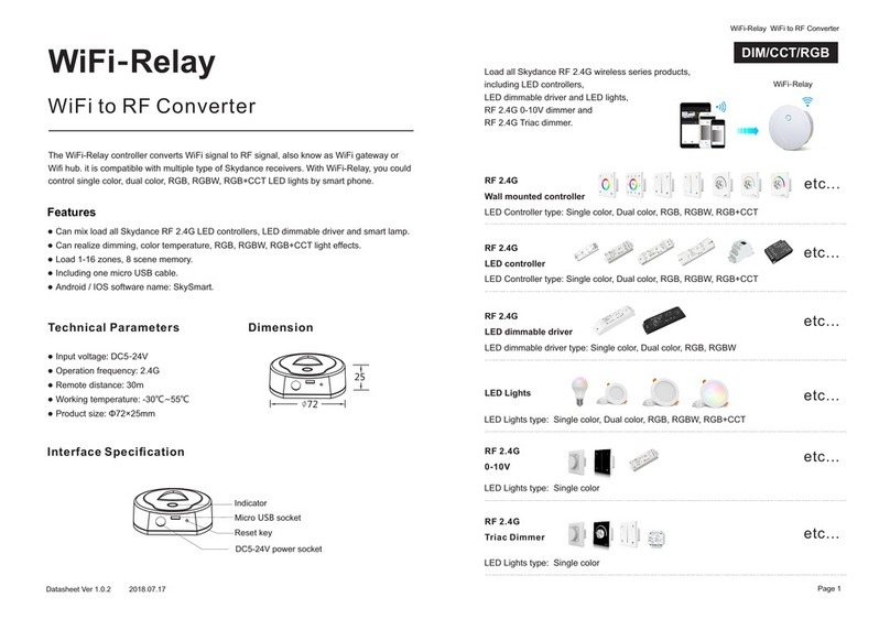
SKYDANCE WiFi-Relay User manual

SKYDANCE

SKYDANCE WiFi-Relay User manual

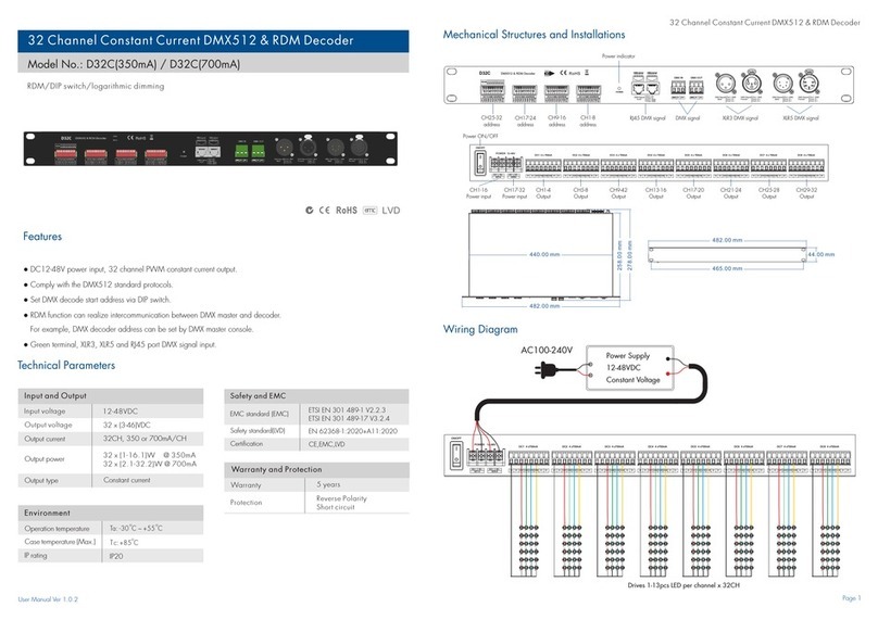
SKYDANCE D32C User manual

SKYDANCE

SKYDANCE D32C User manual

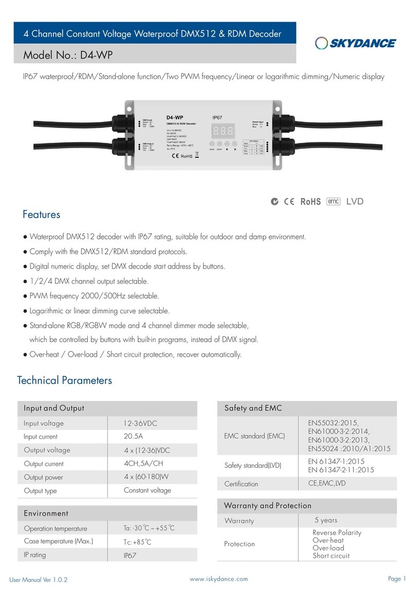
SKYDANCE D4-WP User manual

SKYDANCE

SKYDANCE D4-WP User manual

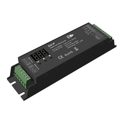
SKYDANCE D4-P User manual

SKYDANCE

SKYDANCE D4-P User manual

SKYDANCE D4-WP User manual

SKYDANCE

SKYDANCE D4-WP User manual

SKYDANCE D4-L User manual

SKYDANCE

SKYDANCE D4-L User manual

SKYDANCE D1-L User manual

SKYDANCE

SKYDANCE D1-L User manual

SKYDANCE D12A User manual

SKYDANCE

SKYDANCE D12A User manual

SKYDANCE D4-P User manual

SKYDANCE

SKYDANCE D4-P User manual

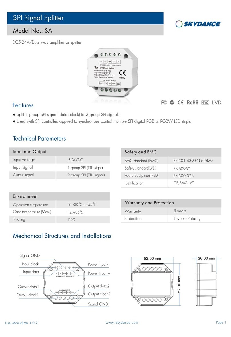
SKYDANCE SA User manual

SKYDANCE

SKYDANCE SA User manual

SKYDANCE SA User manual

SKYDANCE

SKYDANCE SA User manual

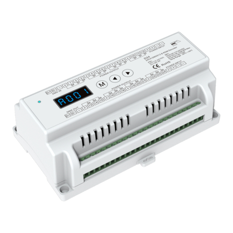
SKYDANCE D24 User manual

SKYDANCE

SKYDANCE D24 User manual

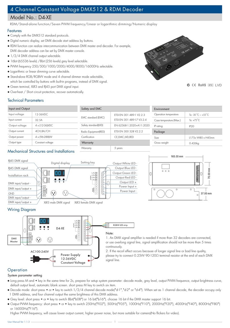
SKYDANCE D4-XE User manual

SKYDANCE

SKYDANCE D4-XE User manual

SKYDANCE D1-L User manual

SKYDANCE

SKYDANCE D1-L User manual

Popular Media Converter manuals by other brands

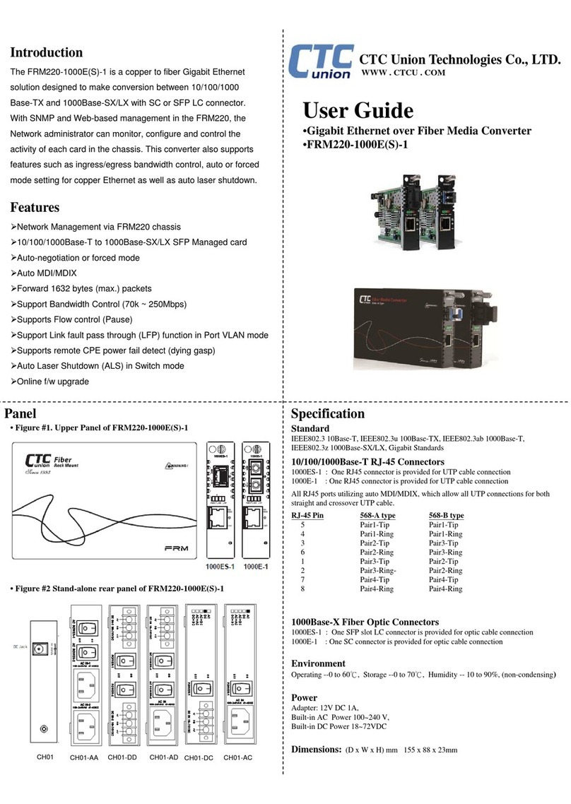
CTC Union FRM220-1000E-1 user guide

CTC Union

CTC Union FRM220-1000E-1 user guide

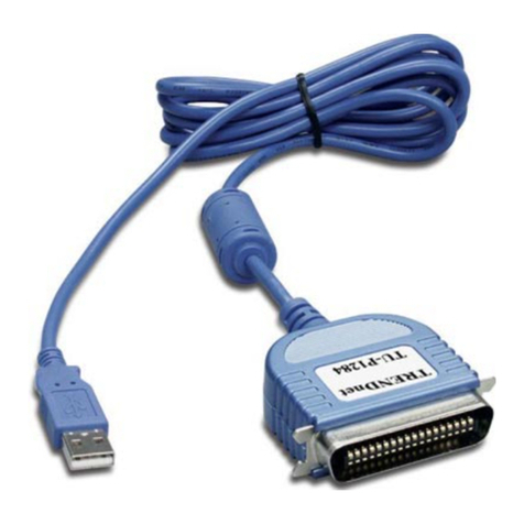
TRENDnet TU-P1284 Quick installation guide

TRENDnet

TRENDnet TU-P1284 Quick installation guide

PCB Piezotronics 422E03 Installation and operating manual

PCB Piezotronics

PCB Piezotronics 422E03 Installation and operating manual

Chino D01M user manual

Chino

Chino D01M user manual

Delta-Opti DHI-VTNC3000A user manual

Delta-Opti

Delta-Opti DHI-VTNC3000A user manual

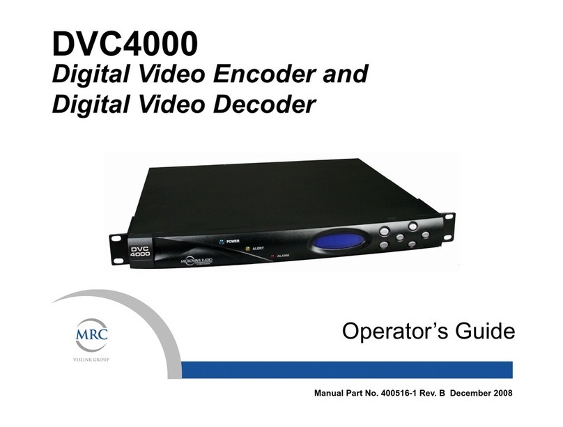
Microwave Radio DVC 4000 Operator's guide

Microwave Radio

Microwave Radio DVC 4000 Operator's guide

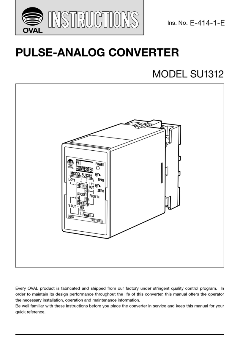
Oval SU1312 instructions

Oval

Oval SU1312 instructions

ZIMO MXULF instruction manual

ZIMO

ZIMO MXULF instruction manual

Caen ELS PreDAC user manual

Caen ELS

Caen ELS PreDAC user manual

ACU-RITE SENC 150 Reference manual

ACU-RITE

ACU-RITE SENC 150 Reference manual

Planet GST-802 user manual

Planet

Planet GST-802 user manual

Black Box LMC5001A installation guide

Black Box

Black Box LMC5001A installation guide

foc.us TView PresoCard user manual

foc.us

foc.us TView PresoCard user manual

NAD 745DAC1 user guide

NAD

NAD 745DAC1 user guide

TV One MAGENTA Pathfinder 500 Series user guide

TV One

TV One MAGENTA Pathfinder 500 Series user guide

Blackmagicdesign ATEM Series Installation and operation manual

Blackmagicdesign

Blackmagicdesign ATEM Series Installation and operation manual

Black Box LHC201A user manual

Black Box

Black Box LHC201A user manual

Planet IPOE-17 S Series user manual

Planet

Planet IPOE-17 S Series user manual

manuals.online logo
manuals.online logoBrands
  • About & Mission
  • Contact us
  • Privacy Policy
  • Terms and Conditions

Copyright 2025 Manuals.Online. All Rights Reserved.