manuals.online logo
Brands
  1. Home
  2. •
  3. Brands
  4. •
  5. SKYDANCE
  6. •
  7. Media Converter
  8. •
  9. SKYDANCE D4-P User manual

SKYDANCE D4-P User manual

Technical Parameters
1
User Manual Ver 1.1.4
Features
Input and Output
Operation temperature
Environment
Ta: -30
O
C ~ +55
O
C
Gross weight
Size
Package
Case temperature (Max.)
IP rating IP20
Ta: +75
O
C
Safety and EMC
EMC standard (EMC) ETSI EN 301 489-1 V2.2.3
ETSI EN 301 489-17 V3.2.4
Radio Equipment(RED) ETSI EN 300 328 V2.2.2
Certication CE,EMC,LVD,RED
EN 62368-1:2020+A11:2020
Safety standard(LVD)
Warranty
5 years
Warranty
L178x W50 x H38mm
0.295kg
Model No.: D4-P / D4-E
4 Channel Constant Voltage DMX512 & RDM Decoder
RDM/Numeric display Seven PWM frequency/Linear or logarithmic dimming/ /Multiple protection
D4-P D4-E
● Comply with the DMX512 standard protocols.
● Digital numeric display, set DMX decode start address by buttons.
● RDM function can realize intercommunication between DMX master and decoder.
For example, DMX decoder address can be set by DMX master console.
● 1/2/4 DMX channel output selectable.
● 16bit (65536 levels) /8bit (256 levels) grey level selectable.
● PWM frequency 250/500/1000/2000/4000/8000/16000Hz selectable.
● Logarithmic or linear dimming curve selectable.
● Over-heat / Over-load / Short circuit protection, recover automatically.
● D4-P have Green terminal DMX signal ports, D4-E have RJ-45 DMX signal ports.
Mechanical Structures and Installations
DMX input / output
DMX input / output
Power input -
Power input +
Output LED +
Output Red LED -
Output Green LED -
Output Blue LED -
Output White LED -
Setting key
Digital display
+
+
+
D4-P
OUTP UT
1 2 3
GB
WW C W
R
WW
W
CW
4
IN PU T
12-48VDC
GN D
D
D
D
D
GN D
DM X in/o ut DM X in/o ut
M
Installation rack
DMX Sign al
RJ45
1 2 3 4 5 6 7 8
DM X in/o ut
Pin7: GN D
Pin8: GN D
1 2 3 4 5 6 7 8
DM X in/o ut
Pin2: D
Pin1: D
DMX input / output
DMX input / output
Power input -
Power input +
Output LED +
Output Red LED -
Output Green LED -
Output Blue LED -
Output White LED -
Setting key
Digital display
+
+
+
OUTP UT
1 2 3
GB
WW C W
R
WW
W
CW
4
IN PU T
12-48VDC
M
Installation rack
D4-E
32.00 mm
46.00 mm
175.00 mm
24.00 mm
168.00 mm
24.00 mm
+
+
+
D4-P
OUTP UT
1 2 3
GB
WW C W
R
WW
W
CW
4
IN PU T
12-48V DC
GN D
D
D
D
D
GN D
DM X in/o ut DM X in/o ut
M
DMX
Master AC100-240V
Power Supply
12-48VDC
Constant Voltage
RGBW LED strip
W
Wiring Diagram
Note:
1. An DMX signal amplifier is needed if more than 32 decoders are connected, or use overlong signal line, signal amplification should not be more
than 5 times continuously.
2. If the recoil effect occurs because of longer signal line or bad line quality, please try to connect 0.25W 90-120Ω terminal resistor at the end of
each DMX signal line.
4×96W @12V 4×192W@24V
4×216W@36V 4×288W@48V
Constant voltage
4 x (12-48)VDC
12-48VDC
32.5A
4×8A@12/24V
4×6A@36/48V
Output type
Output power
Output voltage
Output current
Input voltage
Input current
LVD
2
User Manual Ver 1.1.4
Operation
System parameter setting
● Long press M and ◀ key in the same time for 2s, prepare for setup system parameter: decode mode, grey level, output PWM
frequence, output brightness curve, default output level, automatic blank screen. short press M key to switch six item.
● Decode mode: short press ◀ or ▶ key to switch 1/2/4 channel decode mode(”d-1",”d-2" or “d-4"). When set as 1 channel decode, the decoder occupy only 1
DMX address, and four channel output the same brightness of this DMX address.
● Grey level: short press ◀ or ▶ key to switch 8bit(“b08") or 16 bit(“b16"). choose 16 bit if the DMX master support 16 bit.
● Output PWM frequency: short press ◀ or ▶ key to switch 250Hz(“F02"), 500Hz(“F05"), 1000Hz(“F10"), 2000Hz(“F20"), 4000Hz(“F40"), 8000Hz(“F80") or
16000Hz(“F16").
Higher PWM frequency, will cause lower output current, higher power noise, but more suitable for camera(No ickers for video).
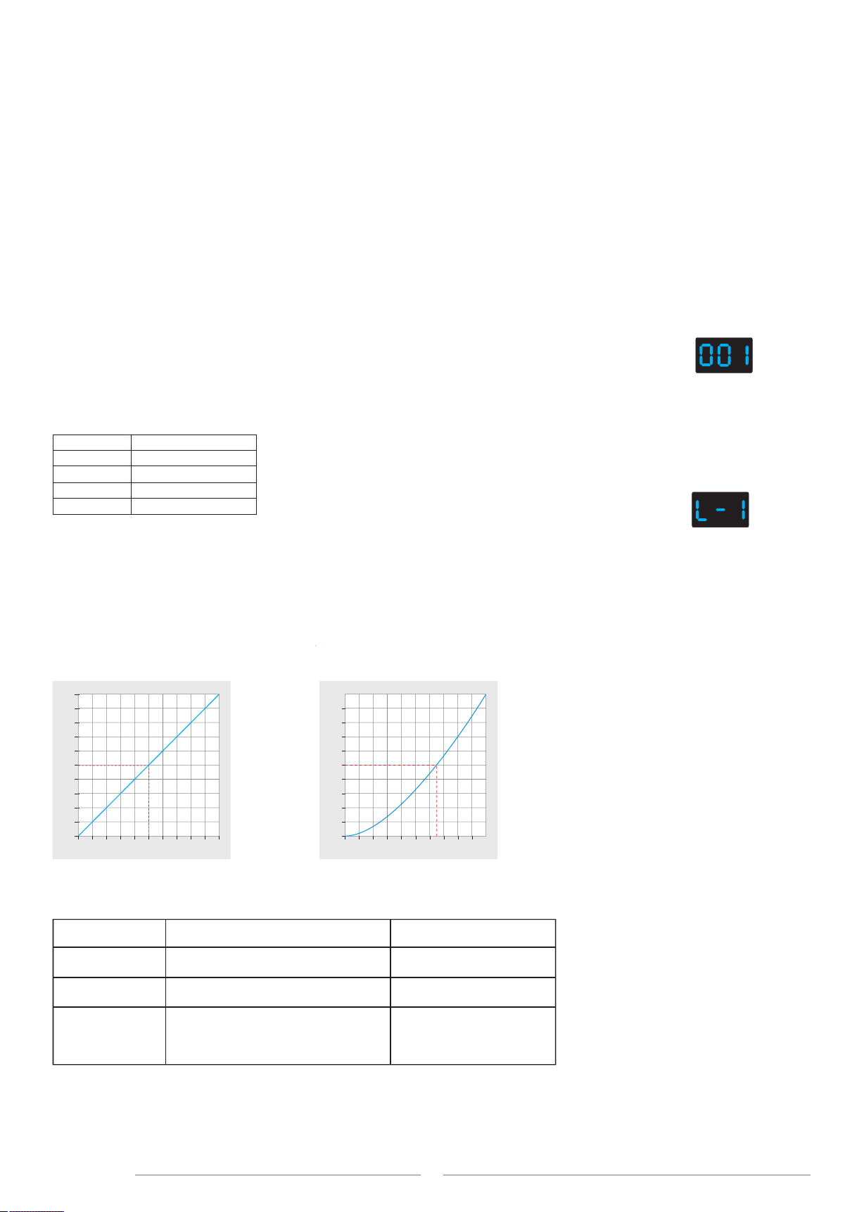
● Output brightness curve: short press ◀ or ▶ key to switch linear curve(“C-L") or logarithmic curve(“C-E").
● Default output level: press ◀ or ▶ key to change default 0-100% level (“d00" to “dFF" ) when no DMX input signal.
● Automatic blank screen: short press ◀ or ▶ key to switch enable (“bon") or disable(“boF") automatic blank screen.
● Long press M key for 2s or timeout 10s, quit system parameter setting.
● Short press M key, when display 001~512, enter DMX mode.
● Press ◀ or ▶ key to change DMX decode start address(001~512), long press for fast adjustment.
● If there is a DMX signal input, will enter DMX mode automatically.
● DMX Dimming: Each D4-P/D4-E DMX decoder occupy 4 DMX address when connecting the DMX console.
For example, the defaulted start address is 1, their corresponding relationship in the form:
DMX mode
(001~512)
DMX mode
CH1 0-255
CH2 0-255
CH3 0-255
CH4 0-255
CH1 PWM 0-100% (LED R)
DMX Console DMX Decoder Output
CH2 PWM 0-100% (LED G)
CH3 PWM 0-100% (LED B)
CH4 PWM 0-100% (LED W)
Self-test mode
● Enter self-test mode only when DMX signal is disconnected or lost.
● Short press M key, when display L-1~L-5, enter self-test mode.
● Press ◀ or ▶ key to change mode number(L-1L-5).
● Self-test mode include four channel light up separately or synchronously.
(L-1~L-5)
Self-test mode
Dimming curve setting
Linear dimming curve Logarithmic dimming curve
100
90
80
70
60
50
40
30
20
10
PWM duty(%)
100
90
80
70
60
50
40
30
20
10
PWM duty(%)
50 60 70 80 90 100
Brightness(%)
10 20 30 40
Gamma=1.6
50 60 70 80 90 100
Brightness(%)
10 20 30 40
Gamma=1.0
100
90
80
70
60
50
40
30
20
10
PWM duty(%)
Malfunctions analysis & troubleshooting
1. Wrong connection of R/G/B/W wires.
2. DMX decode address error.
Causes
1. Output cable is too long.
2. Wire diameter is too small.
3. Overload beyond power supply capability.
4. Overload beyond controller capability.
1. No power.
2. Wrong connection or insecure.
Wrong color
Malfunctions
Uneven intensity
between front and
rear,with voltage drop
No light
1. Reconnect R/G/B/W wires.
2. Set corrrect decode address.
Troubleshooting
1. Reduce cable or loop supply.
2. Change wider wire.
3. Replace higher power supply.
4. Add power repeater.
1. Check the power.
2. Check the connection.

This manual suits for next models

1

Other SKYDANCE Media Converter manuals

SKYDANCE D1-L User manual

SKYDANCE

SKYDANCE D1-L User manual

SKYDANCE WiFi-Relay User manual

SKYDANCE

SKYDANCE WiFi-Relay User manual

SKYDANCE D12A User manual

SKYDANCE

SKYDANCE D12A User manual

SKYDANCE D5 User manual

SKYDANCE

SKYDANCE D5 User manual

SKYDANCE D4-WP User manual

SKYDANCE

SKYDANCE D4-WP User manual

SKYDANCE D4-L User manual

SKYDANCE

SKYDANCE D4-L User manual

SKYDANCE D4-P User manual

SKYDANCE

SKYDANCE D4-P User manual

SKYDANCE D4-WP User manual

SKYDANCE

SKYDANCE D4-WP User manual

SKYDANCE D4-XE User manual

SKYDANCE

SKYDANCE D4-XE User manual

SKYDANCE D4-WPS User manual

SKYDANCE

SKYDANCE D4-WPS User manual

SKYDANCE SA User manual

SKYDANCE

SKYDANCE SA User manual

SKYDANCE SA User manual

SKYDANCE

SKYDANCE SA User manual

SKYDANCE D24 User manual

SKYDANCE

SKYDANCE D24 User manual

SKYDANCE D32C User manual

SKYDANCE

SKYDANCE D32C User manual

SKYDANCE D1-L User manual

SKYDANCE

SKYDANCE D1-L User manual

Popular Media Converter manuals by other brands

Mobileye RS-485 Installation & user guide

Mobileye

Mobileye RS-485 Installation & user guide

Kenwood SS-992 instruction manual

Kenwood

Kenwood SS-992 instruction manual

Advantech BB-422PP9TB quick start guide

Advantech

Advantech BB-422PP9TB quick start guide

Z3 Technology Z3-DM816X-PCI2-RPS Developer's guide

Z3 Technology

Z3 Technology Z3-DM816X-PCI2-RPS Developer's guide

ELPRO KM03-HE02 Series quick start guide

ELPRO

ELPRO KM03-HE02 Series quick start guide

Hagstrom KEAD6 user manual

Hagstrom

Hagstrom KEAD6 user manual

Bose SoundTouch 30 owner's guide

Bose

Bose SoundTouch 30 owner's guide

ION Video 2 PC HD quick start guide

ION

ION Video 2 PC HD quick start guide

Extron electronics AXI 016 Setup guide

Extron electronics

Extron electronics AXI 016 Setup guide

Canoga Perkins L322 user manual

Canoga Perkins

Canoga Perkins L322 user manual

marklin 60905 user guide

marklin

marklin 60905 user guide

Lika IQ58 manual

Lika

Lika IQ58 manual

Belle BGF 24 Operator's manual

Belle

Belle BGF 24 Operator's manual

PMA Mobile 0430 manual

PMA Mobile

PMA Mobile 0430 manual

CEL-MAR ADA-4040PC3 user manual

CEL-MAR

CEL-MAR ADA-4040PC3 user manual

Advantech BB-SCP211-DFTB3 quick start guide

Advantech

Advantech BB-SCP211-DFTB3 quick start guide

UTEPO MC2-FS user manual

UTEPO

UTEPO MC2-FS user manual

Harman AMX N2600 Series instruction manual

Harman

Harman AMX N2600 Series instruction manual

manuals.online logo
manuals.online logoBrands
  • About & Mission
  • Contact us
  • Privacy Policy
  • Terms and Conditions

Copyright 2025 Manuals.Online. All Rights Reserved.