Skylab SKW75 User manual

Skylab M&C Technology Co., Ltd.
SKW75-User Manual
SKW75-UM-001,A/1
1
SKW75 User Manual
General Description
The
module
SKW75
compliant to
802.11
b/g/n
Wi-Fi
Solution for
low
power,
low-cost,
and
highly
integrated
AP
and
consumer
electronic devices,
the
module
requiring
only
a
external
3.3V
power
supply
.
The
module
based
on
the
single
chip
MT7620N
which
integrates
an
802.11n
MAC/BB/radio
with
internal
PA
and
LNA.
It
supports
802.11n
operations
up
to
144
Mbps
for
20
MHz and
300
Mbps
for
40
MHz
channel
respectively,
and
IEEE
802.11b/g
data
rates
.
The
module
support
AP
mode
and
client
mode
and router mode
.
Applications
AP WIFI
3G/4G wifi router
Repeater WIFI
IP TV
IP DVD(Internet VOD Player)
Set Top Box
Home Gateways
Gaming Consoles
DVR
Features
Compliant to IEEE 802.11b/g/n WLANs
2T2R Mode with support for a 300Mbps TX/RX PHY rate.
DDR2 memory up to 512Mb
Flash memory up to 64Mb
4LAN
ports
and
1WAN
port
Support USB
2.0
host device
Support USB disk.
Support AP/Client/Router mode
Skylab M&C Technology Co., Ltd. SKW75-User Manual
SKW75-UM-001,A/1
2
Security: WEP 64/128, WPA, WPA2, TKIP, AES, WAPI
RoHS compliance meets environment-friendly requirement.
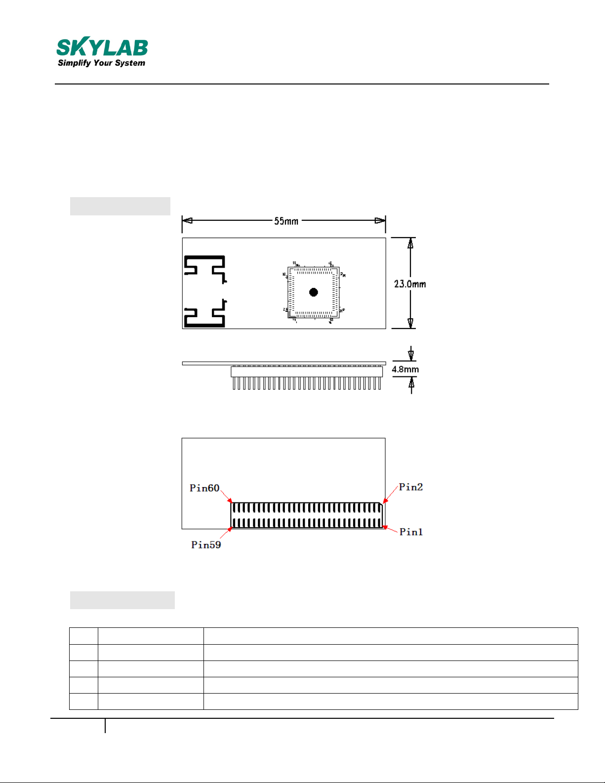
55(L) x 23(W) x 4.80(H) mm small dimension
Module Pinout
Figure 1: SKW75 Pin Name
Pin Description
1
PORT1_RX+
Ethernet port
2
PORT1_TX+
Ethernet port
3
PORT1_RX-
Ethernet port
4
PORT1_TX-
Ethernet port
5
PORT2_RX+
Ethernet port
Skylab M&C Technology Co., Ltd. SKW75-User Manual
SKW75-UM-001,A/1
3
6
NC
No Connect
7
PORT2_RX-
Ethernet port
8
NC
No Connect
9
PORT2_TX+
Ethernet port
10
LINK2
Port #2 activity LED
11
PORT2_TX-
Ethernet port
12
LINK3
Port #3 activity LED
13
PORT 3_TX+
Ethernet port
14
LINK4
Port #4 activity LED
15
PORT 3_TX-
Ethernet port
16
NC
No Connect
17
PORT 3_RX+
Ethernet port
18
NC
No Connect
19
PORT 3_RX-
Ethernet port
20
NC
No Connect
21
GND
Ground
22
VDD_3.3V
3.3V input 600mA, recommended voltage 3.3V,Min2.97V,
MAX 3.63V
23
PORT0_RX+
Ethernet Wan port
24
NC
No Connect
25
PORT0_RX-
Ethernet Wan port
26
NC
No Connect
27
PORT0_TX+
Ethernet Wan port
28
NC
No Connect
29
PORT0_TX-
Ethernet Wan port
30
NC
No Connect
31
PORT4_RX+
Ethernet port
32
RESET
Resets the firmware to its default configuration
33
PORT4_RX-
Ethernet port:
34
WPS_PBC
WPS Input Pin
35
PORT4_TX+
Ethernet port
36
USB +
USB signal, carries USB data to and from the USB 2.0 PHY
37
PORT4_TX-
Ethernet port
38
USB -
USB signal, carries USB data to and from the USB 2.0 PHY
39
GND
Ground
40
NC
No Connect
41
NC
No Connect
Skylab M&C Technology Co., Ltd. SKW75-User Manual
SKW75-UM-001,A/1
4
42
GPIO0
GPO0(output only)
43
NC
No Connect
44
RESET
Resets the firmware to its default configuration, it has a internal
45
GND
Ground
46
WPS_PBC
WPS Input Pin
47
NC
No Connect
48
GND
Ground
49
NC
No Connect
50
VDD_3.3V
3.3V input 600mA, recommended voltage 3.3V,Min2.97V,
MAX 3.63V
51
NC
No Connect
52
VDD_3.3V
3.3V input 600mA, recommended voltage 3.3V, Min2.97V,
MAX 3.63V
53
LINK1
Port #1 activity LED
54
LINK0
Port #0 activity LED
55
WIRELESS_L
Wireless LED
56
NC
No Connect
57
UART_TX
Serial data out
58
UART_RX
Serial data in
59
GND
Ground
60
GND
Ground
PCB Dimensions
Figure 2: SKW75 Dimensions
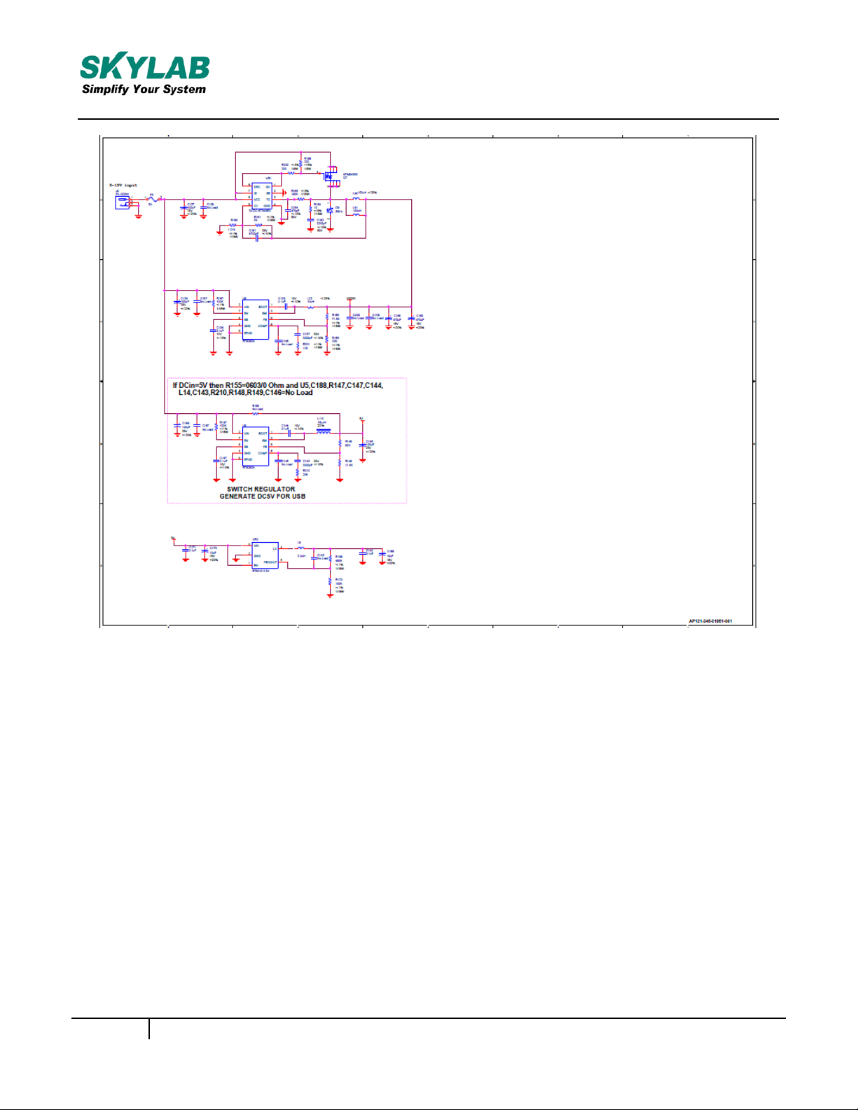
Reference design schematic
Skylab M&C Technology Co., Ltd. SKW75-User Manual
SKW75-UM-001,A/1
5
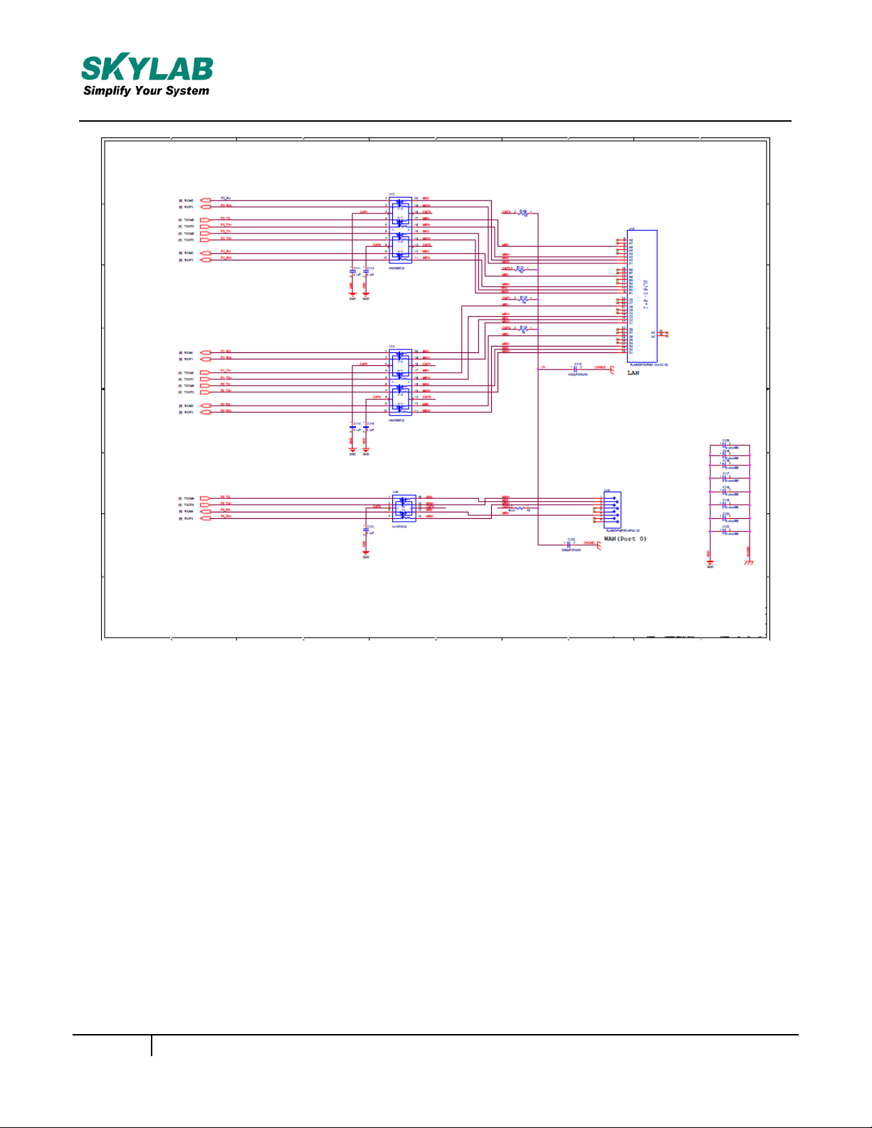
Skylab M&C Technology Co., Ltd.
SKW75-User Manual
SKW75-UM-001,A/1
6
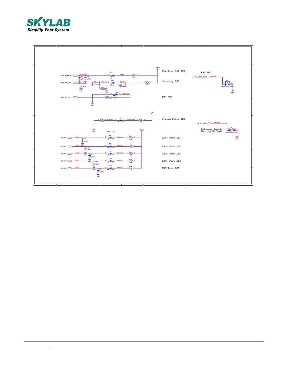
Skylab M&C Technology Co., Ltd.
SKW75-User Manual
SKW75-UM-001,A/1
7
Figure 3: SKW75 Reference design schematic

Skylab M&C Technology Co., Ltd. SKW75-User Manual
SKW75-UM-001,A/1
8
FCC Statement
Changes or modifications not expressly approved by the party responsible for compliance
could void the user's authority to operate the equipment.
This equipment has been tested and found to comply with the limits for a Class B digital device,
pursuant to Part 15 of the FCC Rules. These limits are designed to provide reasonable
protection against harmful interference in a residential installation. This equipment
generates uses and can radiate radio frequency energy and, if not installed and used in
accordance with the instructions, may cause harmful interference to radio communications.
However, there is no guarantee that interference will not occur in a particular installation. If this
equipment does cause harmful interference to radio or television reception, which
can be determined by turning the equipment off and on, the user is encouraged to try to
correct the interference by one or more of the following measures:
-- Reorient or relocate the receiving antenna.
-- Increase the separation between the equipment and receiver.
-- Connect the equipment into an outlet on a circuit different from that to which the
-- Consult the dealer or an experienced radio/TV technician for help
receiver is connected.
This device complies with part 15 of the FCC rules. Operation is subject to the following two
conditions (1)this device may not cause harmful interference, and (2) this device must
accept any interference received, including interference that may cause undesired operation
FCC Radiation Exposure Statement
The modular can be installed or integrated in mobile or fix devices only.
This modular cannot be installed in any portable device, for example,
USB dongle like transmitters is forbidden.
This modular complies with FCC RF radiation exposure limits set forth
for an uncontrolled environment. This transmitter must not be coÿlocated
or operating in conjunction with any other antenna or transmitter.
This modular must be installed and operated with a minimum distance of 20
cm between the radiator and user body.
If the FCC identification number is not visible when the module
is installed inside another device, then the outside of the device into which the
module is installed must also display a label referring to the enclosed module.
This exterior label can use wording such as the following:
“Contains Transmitter Module FCC ID:2ACOE-SKW75 Or Contains FCC ID:2ACOE-SKW75”
when the module is installed inside another device, the user manual of this device must contain below warning statements;
1. This device complies with Part 15 of the FCC Rules. Operation is subject to
the following two conditions:
(1) This device may not cause harmful interference.
(2) This device must accept any interference received, including interference
that may cause undesired operation.
2. Changes or modifications not expressly approved by the party responsible
for compliance could void the user's authority to operate the
equipment.
The devices must be installed and used in strict accordance with the
manufacturer's instructions as described in the user documentation that
comes with the product.
Table of contents
Other Skylab Control Unit manuals


Popular Control Unit manuals by other brands


Alemite
Alemite 343683 Installation and maintenance instructions

Watts
Watts AMES 930GD Installation, operation and maintenance manual

H3C
H3C NSQ1TGS32SF0 manual

STIEBEL ELTRON
STIEBEL ELTRON GWS 1 Installation

Blain Hydraulics
Blain Hydraulics EV Series Service manual

Emerson
Emerson Alco Controls CX2 operating instructions


