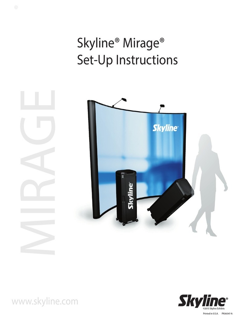
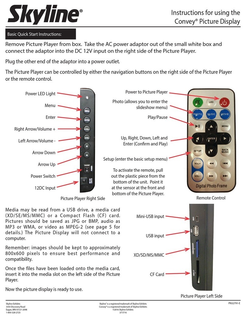
SkyLine Mirage Plus Manual

1
Table of Contents
Cases
Frame Identification
Component Identification
Frame
Channels
Halogen Lights
SkyTrak™Lights
Panels
End Panels
Detachable Graphics
Marquee Header
Shelving
Product Display
Bubble Panel
Case Table – Transporter Case
Transporter Cases
Warranty
Set-Up
Accessories
Repacking
Mirage®Plus is available two sizes – 8’ and 10’ wide backwalls. The following set-up and repacking
instructions depict our 10’ 92” Mirage Plus. Both Mirage displays set up using the same sequence,
although the number of components vary between models.
Please read the entire section before attempting set-up.
Although Skyline products are designed to withstand the rigors of a heavy trade show schedule, with many
set-ups and take-downs, care should be taken when handling your display. Valuable graphic panels can
be damaged if not properly handled. Place graphic panels in protective plastic bags provided before
repacking. Be careful not to drop panels into the case as this could damage their edges.
If you have any questions about setting up your display or have lost components, call your local Skyline
distributor. For the number of your distributor, or the distributor in a city in which you are exhibiting, call
Skyline at 1-800-328-2725.
Thank you for choosing Skyline – have a great show!
2
2
3
4
6
8
10
12
13
14
15
18
19
20
22
23
27

Transporter Case
Cases connect for easy
transporting.
To open case lid, flip latches up
and rotate counter-clockwise to
loosen.
Remove case connector bracket
and put in a safe place for
reconnecting your cases after
your show.
8’ 92” 10’ 92”
2
Case connector
bracket
Case
Frame Identification
Mirage®Plus is available two sizes – 8’ and 10’ wide backwalls. Both Mirage displays set up using the
same sequence, although the number of components vary between models.

3
Channels
Light package (optional)
Panels
End panels
Core
Core tray
Light cord
Transporter case
Protective bag
Frame
Transporter Case Components

Remove frame from protective
bag in center core of case.
(Keep protective bag for repacking
your frame.)
Place frame in standing position
with blue hubs up and facing
you. Spread frame apart enough
to grasp the rod in the center of
the frame (about 2’ square).
4
1
Frame
2
Frame
Blue hubs

Frame will lock into place when it
is fully expanded.
Grasp frame rod with label
attached in the center of the
frame and lift to expand frame.
5
3
Blue hubs

If you have no lights or a backlit
Marquee header proceed to Step 5.
If you have Halogen lights go
directly to Step 8-H on page 8.
If you have SkyTrak lights go
directly to Step 8-S on page 10.
Remove channel from case core.
Identify what lights you have, if
any, before you install the
channels (see below).
Your channels are hinged for easy
set up. The light clip is on the top
channel.
3-section channel
with hinges
Top
Bottom
6
Channel
4
!
Channels

Channels are applied to all
quadrants on front side of frame.
Extra channels are applied to
each end on back side of frame.
Top Connection
Connect top channel section to
top hub of display frame.
Center Connection(s)
Connect bottom of top channel
to hub of display frame. Slide
top of next channel up onto
same hub.
Bottom Connection
Connect bottom of channel to
hub of display frame.
7
Frame
(from backside)
Hub
Top
Channel
Top
Channel
Center
Channel
Bottom
Channel
Step 5
Step 6
Step 7
5
6
7

Attach light cord to fixture.
The fixture box opens on the side
and is fastened with hook and
loop tabs.
Attach fixture to clip on top
section of channel. Hold down
locking tab and back fixture into
clip.
8
Light cord
Hook and loop tabs
Fixture
Clip on top channel
Locking tab
8-H
Additional
Fixture
Halogen Lights

Rotate fixture 90º counter-clockwise.
Repeat for remaining fixture(s).
See Steps 5-7 for details on
channel installation.
Place channels with light fixtures
in desired position on frame (see
illustration at right for typical
placement).
Remaining channels without lights
are installed on open quadrants
on front of frame and on end
quadrants on back of frame.
9

Attach SkyTrak fixtures to light
cord (found in lid of Transporter
case).
Attach assembled fixture to clip
on top section of channel. Hold
down locking tab and back
fixture into clip.
The fixture box opens on the side
and is fastened with hook and
loop tabs.
10
8-S
Light cord
Clip on top channel
Locking tab
SkyTrak™Lights

Repeat for remaining fixtures.
See Steps 5-7 for details on
channel installation.
Place channels with light fixtures
in desired position on frame (see
right for typical placement).
Remaining channels are installed
on remaining quadrants on front
of frame (if any) and on end quad-
rants on back of frame.
Rotate fixture 90º counter-clockwise.
11

Carefully remove panels from case
and unroll on flat, clean surface.
Hint: Roll panels slightly tighter to remove
from case.
Note: Remove center core from
Transporter case to access panels.
Graphic Panel:
Pull just enough
of the panel out of the bag to
expose the panel notches. Attach
as desribed below(11). Once
panel is attached, slide bag off of
panel.
Fabric Panels:
Remove panel(s)
from protective bag and attach as
described below (11).
Save bags and protective sheets.
Grasp panels on their edges making
sure panel notches are
on top.
Hold the panel slightly
concave to
give it the rigidity needed to reach
the top of the channel.
Hook the panel notch over the pin
at the top of the channel. Repeat
for other side of panel. Let panels
attach to magnetic channels.
12
Panels
Panel notch
Fabric panel
Pin
Graphic panel
Protective bag
9
10
11
Panels

Hook the panel notch over the pin
at the top of the front
channel.
Let panel attach to
magnet on channel. Guide end
panel around to back of frame
and attach in the same manner.
13
Front channel
Back channel
Panel notch
Pin
12
End Panels

Header Panel Line up header
with top of fabric panel and unroll
keeping header tight to panel.
Optional Graphics
14
Header panel
End panel
13
Detachable Graphics

15
Marquee Lights Remove light
bulbs from protective foam covers.
Screw bulbs into light bar and
swivel hanging brackets up.
The Marquee Header is a graphic
header designed to be backlit.
It can be backlit with either
incandescent Marquee Lights or
Flourescent Lightsticks.
Hang light brackets over display
frame. Place cord over top of
display and plug into power strip.
Skip to Step 5.
If you have Marquee lights
proceed to Step 1.
If you have a Fluorescent
Lightstick skip to Step 3
on page 16.
Hanging bracket
Frame
Hanging bracket
Protective cover
1
2
Marquee Header

Fluorescent Lightstick Insert
both lightsticks into fixture.
Unfold hanging bracket and insert
into slots of channels in desired
position.
Connect fixture to hanging bracket.
Place cord over top of display
and plug into power strip.
16
Fixture
(Top View)
Hanging bracket
Fixture
Channel
Fluorescent lightsticks
Fixture
Single Lightstick
Double Lightstick
Hanging bracket
Fluorescent lightsticks
Channel
3
4
Fluorescent lightsticks

Assemble shock-corded header
frame.
Unroll graphic panel onto header
frame.
Hook header over frame at both
ends of display.
17
Frame
Hanging bracket
Graphic panel
Shockcord
Frame
5
6
7
Hanging bracket

Product Shelf Pull panel away
from frame to expose channel.
Attach shelf bracket to channel
and secure in
place. Repeat for
opposite bracket.
Place shelf onto
brackets making sure notches
line up.
Product shelving is flat.
Available as single or double
shelf.
Literature shelving is angled
and is
available only as a double
shelf.
Literature Shelf Pull panel
away from frame to expose chan-
nel.
Attach shelf bracket to chan-
nel
and secure in place. Repeat
for opposite bracket.
Attach literature clip to shelf lip.
Place shelf onto brackets making
sure notches line up.
18
Shelf bracket
Channel
Double shelf
Shelf bracket
Shelf
Literature clip
Channel
Shelf
1
1
2
Literature Shelf
Product Shelf
Shelving

Waterfall Bracket Carefully
pull panel away exposing channels.
Insert bracket into channel
notches and push down to lock
into place.
Peg Bar Carefully pull panel
away exposing channels. Insert
bracket into channel notches and
push down to lock into place.
Waterfall Bracket is used for
displaying products with a
hanger such as apparel.
Peg Bar is perfect for displaying
packaged items.
19
Waterfall bracket
Channel
Channel
Peg bar
Peg
1
1
Product Display

Insert lightstick into fixture at an
angle and snap into place.
Repeat for remaining lightstick.
Connect reflector panel by hooking
the panel notches over the pins at
the top of the channels.
Push keyhole slot of panel onto
hub of display frame.
The Bubble Panel gives added
dimension to your Mirage and
allows for full-panel backlit
graphics.
20
1
2
Fixture
(Top View)
Fluorescent lightsticks
Keyhole
slot
Reflector panel
Hub
Bubble™Panel
Table of contents
Other SkyLine Monitor manuals
