If, within one year from date of purchase, this product should become defective
(except battery), due to faulty workmanship or materials, it will be repaired or
replaced, without charge. Proof of purchase and a Return Authorization are required.
10. WARRANTY
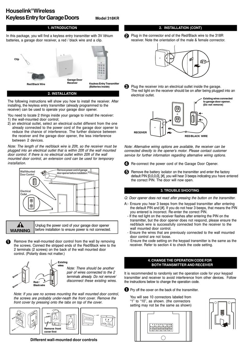
Onthegaragedoorreceiver
and wireless switch receiver,
removethescrewthatholds
theconnectorcovers,and
remove the covers.
You willsee10connectors. Forconnectors“1”to“9”,thesettings
must match with those of the transmitter.
Connector 10 on the receiver should be set to “+” if it is controlled by
the transmitter’s left button , connector 10 on the receiver should be
removed if it is controlled by the transmitter’s right button. Example, if
theleftbuttonis usedtocontrolthegarage doorreceiver,connector
10on the garage door receivershouldbe set to ”+”. Ifthe right button
is used to control the wireless switch receiver, connector 10 on the
wirelessswitchreceivershouldberemoved.
Connector 10 “Removed”
Connector 10 set to “+” TRANSMITTER
Youcanaddasmanyadditionaltransmittersasyou
wanttocontrolthesamereceiver. Simplysetthesame
operationcodeonalltransmitterswiththesamecode
setting on the receiver. Skylink®offersKeychain
TransmitterModel 318TNtoworkwith yourreceiver.For
moreinformation,pleasevisitourwebsiteat
www.skylinkhome.com or contact us.
7. ADDITIONAL TRANSMITTER
RISKOFELECTRICALSHOCK.FORINDOORUSEONLY.
CAUTION:NOTFORUSEWITHDIMMER.
CAUTION:DISCONNECTPOWERBEFORECODECHANGING.
REPLACECOVERAFTERCODECHANGING.
8. CAUTION
9. FCC
ThisdevicecomplieswithPart15of theFCCRules.Operationissubjectto thefollowingtwoconditions:
(1)Thisdevicemay not cause harmful interference,and(2) This device must acceptanyinterference
received, including interference that may cause undesired operation.
WARNING:
Changesormodificationsto this unit not expresslyapprovedby the party responsible forcompliancecould
voidtheuser’s authority tooperatethe equipment.
NOTE:
Thisequipment hasbeentested andfound tocomplywith thelimits foraClass Bdigital device,pursuant
toPart15 ofthe FCC Rules.These limits aredesigned toprovide reasonableprotectionagainst harmful
interferenceinaresidentialinstallation.Thisequipment generates,usesandcanradiate radiofrequency
energyand,if not installedand used inaccordancewith the instructions,may cause harmfulinterference
to radio communications.
However, there is no guarantee that interference will notoccur inaparticularinstallation.Ifthisequipmentdoes
cause harmfulinterferencetoradioortelevisionreception, which can be determined by turning the equipment
off andon,the user isencouraged to try to correct the interferencebyoneormore of the followingmeasures:
-Reorient orrelocatethe receivingantenna.
-Increasethe separationbetweenthe equipmentandreceiver.
-Connecttheequipmentinto anoutletonacircuit differentfromthattowhich thereceiverisconnected.
-Consultthe dealer oran experienced radio/TVtechnicianfor help.
5
6
7
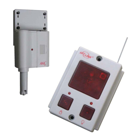
WIRELESS SWITCH RECEIVER
SW-318R
GARAGE DOOR RECEIVER
318R
Connectors
1 to 9 are
the same.
8Putthe cover and screwback onto the receivers. Installthe garage
door receiver and wireless switch receicer based on previous
illustrationsonsections2and4.
Put the battery cover back onto the transmitter.
Presstheleft buttononthetransmitterto operate thegaragedoorreceiver
orpresstherightbuttontoturn on/offthelight fixture/small appliance.
9
12voltalkalinebattery(size23A)
(included).
It is time to change the battery
when the red LED on the trans-
mitter does not turn on when
either button is pressed.
6. BATTERY
11.CUSTOMER SERVICE
CUSTOMER SERVICE
17 Sheard Avenue, Brampton, Ontario, Canada L6Y 1J3
http://www.skylinkhome.com
P/N. 101A231-002 Rev.2
USPatent.D380895
©2005SKYLINKGROUP
If you would like to order Skylink’s products or have difficulty getting them to work,
please :
1. visit our FAQ website at www.skylinkhome.com, or
3. call our toll free at 1-800-304-1187 from Monday to Friday, 9 am to 5 pm EST.
Fax +800 286-1320
10
MODEL:318R
MaximumRating:
Input:120VAC60Hz2W
MODEL:SW-318R
MaximumRating:
Input:120VAC60Hz
Resistiveload:8A(960W)
Incandescent : 300 watts
MotorLoad:1/3HP
Ifthe connector is placed onthe top and middle posts,thatcolumn is
seton“+”. Iftheconnectorisplacedonthemiddleandbottomposts,
that column is set on “ - ”. If the connector is removed completely,(not
placed on any posts), it is set to “ 0 ”. (see
diagram forexamplesofhowtoseta
columntothethreedifferentpositions).
When removing a connector to set a
column to “ 0 ”,savetheconnectorin
case you change the code at a later date.
Aftersetting up the code connectors on thetransmitter, you
are ready to set the same code on the receivers.
Remove the receiver from the electrical outlet before
changing the code.
3
4
WARNING
2
5. CHANGE THE OPERATION CODE FOR
BOTH TRANSMITTER AND RECEIVERS
1
BATTERY
‘+’ ‘-’
‘0’
Followthe instructions below ifyou want to changethe operation code.
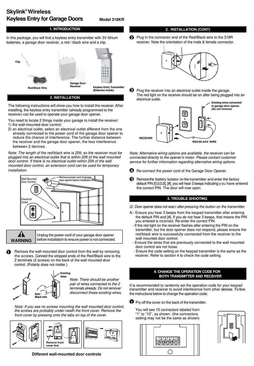
Pry off the battery
cover of the trans-
mitter with a coin,
as shown.
You will see 9 connectors labeled
from “1” to “9”, as shown. (the
connectorssettingmaynotbethe
same as shown.)
You can randomly remove some
connectors,leavingsomeinplace.
Aconnectorcanberemovedwith
the clip, as shown.
