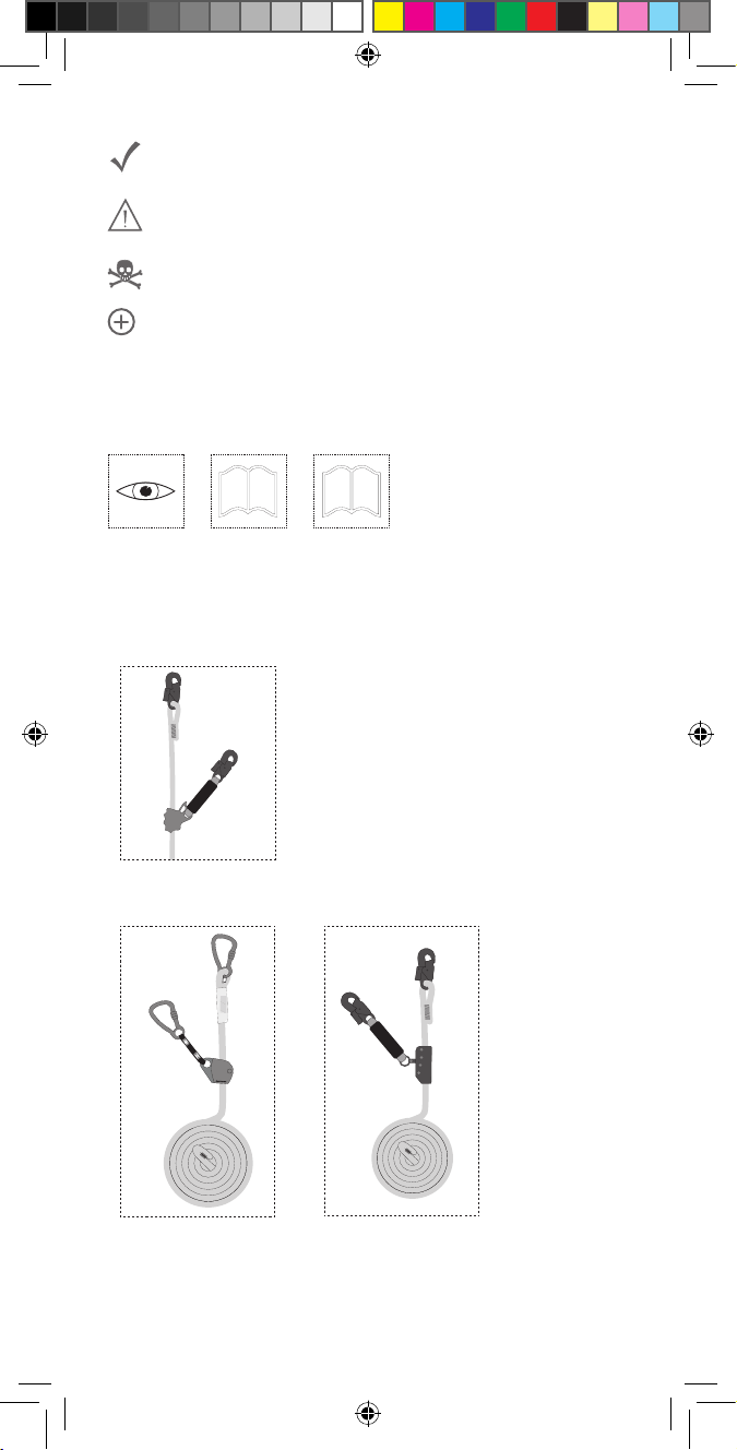
SKYLOTEC Ergogrip SK12 BFD User manual

© SKYLOTEC
MAT-BA-0200-00
Stand 10.05.2019
PSA-VO (EU) 2016/425
2
1
+
SKYLOTEC GmbH
Im Mühlengrund 6-8
56566 Neuwied · Germany
Fon +49 (0)2631/9680-0
Mail [email protected]
Web www.skylotec.com
GEBRAUCHSANLEITUNG
MITLAUFENDE
AUFFANGGERÄTE
EN 353-2
GB
DE
IT
FR
ES
PT
NL
DK
NO
FI
SE
GR
TR
PL
HU
Instruction for use
Gebrauchsanleitung
Istruzioni d‘uso
Instructions d‘utilisation
Instrucciones de uso
Instruções de serviço
Gebruiksaanwijzing
Brugsanvisning
Bruksanvisning
Käyttöohjeet
Bruksanvisning
Οδηγίες χρήσης
Talimatlar
Instrukcje
Utasítás
CZ
SK
RO
SL
BG
EE
LT
LV
RU
RS
HR
Instrukce
Inštrukcie
Instrucţiuni
Navodila
инструкции
Juhised
Instrukcijos
Instrukcijas
Инструкции
Упутство
Instrukcije

2
GB Instructions for use
Icons page 4-8
Explanation page 9-12
DE Gebrauchsanleitung
Icons Seite 4-8
Erklärung Seite 13-16
IT Istruzioni per l'uso
Icone Pagina 4-8
Dichiarazione Pagina 17-21
FR Instructions d'utilisation
Icônes page 4-8
Explication page 22-26
ES Instrucciones de uso
Iconos Página 4-8
Aclaración Página 27-31
PT Manual de instruções de utilização
Ícones páginas 4-8
Declaração página 32-36
NL Gebruiksaanwijzing
Pictogrammen Pagina 4-8
Toelichting Pagina 37-41
DK Betjeningsvejledning
Ikoner Side 4-8
Forklaring Side 42-45
NO Bruksanvisning
Ikoner Side 4-8
Forklaring Side 46-49
FI Käyttöohje
Kuvat Sivu 4-8
Selitys Sivu 50-53
SE Bruksanvisning
Symboler sidan 4-8
Förklaring sidan 54-57
GR Οδηγίες χρήσης
Εικονίδια Σελίδα 4-8
Επεξήγηση Σελίδα58-62
TR Kull anım kılavuzu
Semboller Sayfa 4-8
Açıklama Sayfa 63-66
PL Instrukcja użytkowania
Ikony Strona 4–8
Objaśnienie Strona 67–71
HU
Használati útmutató
Ikonok oldal 4–8.
Magyarázat oldal 72–75.

3
CZ Návod k použití
Ikony strana 4–8
Vysvětlení strana 76–79
SK Návod na použitie
Ikony Strana 4 – 8
Vyhlásenie Strana 80 – 83
RO Instrucțiuni de utilizare
Pictograme Pagina 4–8
Explicare Pagina 84–87
SL Navodila za uporabo
Ikone Stran 4–8
Razlaga Stran 88–91
BG Ръководство за употреба
Икони страница 4 – 8
Декларация страница 92 – 96
EE Kasutusjuhend
Ikoonid Lk 4–8
Selgitus Lk 97–100
LT Naudojimo instrukcija
Piktogramos psl. 4–8
Paaiškinimas psl. 101–104
LV Ekspluatācijas instrukcija
Apzīmējumi lpp. 4–8.
Skaidrojums lpp. 105–108.
RU Руководство по эксплуатации
Условныеобозначения Стр. 4–8
Разъяснение Стр.109–113
RS Упутство за употребу
Иконе Страна 4–8
Објашњење Страна114–117
HR Upute za upotrebu
Ikone Stranica 4 – 8
Objašnjenje Stranica 118 – 121

4
Usage okay/Nutzung in Ordnung
Proceed with caution during usage/
Vorsicht bei der Nutzung
Danger to life/Lebensgefahr
Additional fall arrest security required/
Zusätzliche Absturzsicherung erforderlich
2.) Denition
2.1) Product overview / Produktübersicht
4
3
2
6
1
5
4
2
5
31
5
6
Ergogrip SK12 BFD
SKN BFD SK11
4
3
2
1
MAGIC
5
6
5
MAGIC SK 12
1.) Information (Observe both manuals)/
Informationen (Beide Anleitungen beachten)
2
1+
1.1 1.2

5
1 Flexible anchor line / Bewegliche Führung
2 Guided type fall arrester / Mitlaufendes Auffanggerät
3 + 4 Connector / Verbindungselement EN 362
5 End stitching/Endvernähung oder/or termination knot/
Endknoten
6 Connecting element (energy absorber) /
Verbindungsmittel (Falldämpfer)
Products / Produkte Ergogrip
SK12 BFD
MAGIC
SK12
SKN BFD
SK11
Flexible anchor line /
Bewegliche Führung(1):
Type / Typ
Diameter / Durchmesser
Material
R-060
12 mm
Polyamid
R-062
12 mm
Polyamid
R-080-WE
11 mm
Polyamid
max. user weight / max.
Benutzergewicht 140 kg 100 kg 140 kg
r > 0,5 mm
r < 0,5 mm
2.2) Length of the connecting element + connector /
Länge des Verbindungsmittels + Verbindungselement
L (max. 1,0 m)

6
ERGOGRIP SK12 BFD
L-0448-10
m: 10,0 / ft: 32,8
111111-001
04/2019
E_42X115MM_NORMEN
4030281052845
Im Mühlengrund 6-8
DE 56566 Neuwied
Nahtbereich
Seite
2
0123
www.skylotec.de
2.3) „Exemplary image of a product label“/
„Beispielhafte Darstellung eines Produktetikettes“
E_4 2X115 MM_BENUTZE RID ENTI FI ZI ERUNG
Mark with permanent marker / Mit Permanentmarker
beschriften / Marque avec marqueur permanent
Seite
1
Nahtbereich
QS
Punkt
User identification / Benutzeridentifi-
zierung / Identification de l'utilisateur
/ Identificazione dell' utilizzatore
140 kg
Max. :
E_42X115MM_NORMEN
Normen / Standards
Nahtbereich
Seite
3
11 EN 353-2:2002
Max. :
9.
10.
13.
12.
11.
4.
8.
3.
2.
1.
5.
7.
6.
14.
15.
16.
E_42X115MM_KANTENGETESTET
Nahtbereich
Seite
4
r < 0,5 mm
r > 0,5 mm
17.

7
EN 353-2
+
EN 361
„A“
3.1) 3.2)
„A“
3.3)
3.) Applications/Anwendungen
Fall arrest according to EN 353-2/Absturzsicherung nach EN 353-2
2 x
+ 1 m
+ ε [%]
1 m
2 x
+ 1 m
+ ε [%]
HLi
1 m
H
Anchor point/
Anschlagpunkt
Safety distance /
Sicherheitsabstand
Safety distance/
Sicherheitsabstand
Anchor point/
Anschlagpunkt
Li
3.4) 3.5)
2 x
+ 1 m
+ ε [%]
1 m
2 x
+ 1 m
+ ε [%]
HLi
1 m
H
Anchor point/
Anschlagpunkt
Safety distance /
Sicherheitsabstand
Safety distance/
Sicherheitsabstand
Anchor point/
Anschlagpunkt
Li
3.6)
r < 0,5 mm
Energy absorption by friction /
Kraftreduzierung durch Reibung
Energy absorption with shock
absorber / Kraftreduzierung durch
Falldämpfer (EN 355)
Edge suitability /
Kanteneignung
2 x
+ 2,3 m
+ ε [%]
1 m
H
Anchor point/
Anschlagpunkt
Safety distance /
Sicherheitsabstand
Li
r > 0,5 mm
Horizontal application / horizontale
Anwendung

8
4.1) 4.2) 4.3)
4.4)
4.) How to check before use/Überprüfung vor der Benutzung

9
9
GB Instruction for use
Usage okay
Proceed with caution during usage
Danger to life
Additional fall arrest security required
1.) Information – read carefully
Themanual(1.1“Generalinstructions”,and1.2“Product-specic
instructions”) must be available in the national language at all
times. If not available, then the vendor has to resolve this matter
with SKYLOTEC prior to sale. The instructions must be made
available to the user. The equipment may only be used by
professional users who are in good condition, both mentally and
physically, who have received training in its safe usage and who
possesstherequiredknowledge,orareactingunderthesupervision
of such persons.Arescue plan must be available for any eventuality.
It must be possible to implement rescue measures in a timely
manner.
2.) Denition
2.1) Product overview
1 Flexible anchor line
2 Guided type fall arrester
3 + 4 connector EN 362
5 sewn termination / end knot
6 connecting element (energy absorber)
2.2) The connecting element at the guided type fall arrester may
not be extended!
2.3) Product label
1. Manufacturer, including address
2.lengthoftheexibleanchorline
3. Follow instruction manual
4. Item name
5. Relevant standards + year of issue
6. Serial number
7. CE marking of the supervisory authority
8.Useridentication
9. Next inspection
10. Manufacturer
11. Month and year of manufacture
12. QR code
13. Internal barcode
14. Item number
15. max. number of persons
16. max. rated load, including tools and equipment
17. suitable for horizontal application (edge radius > 0,5 mm)

10
10
3.) Usage
The components of a complete system must never be used
individually or be replaced by non-certied products. The fall
arrester must always be used with the supplied rope.
The system should only be used in accordance with its intended
use. The guided fall arrester must always be attached to an
attachment point marked as "A” on the body harness (EN 361)
(3.1 – 3.3).
During use, pay particular attention to sharp edges, the cable guide
and other things that could damage the rope
or the fall arrester (3.6).
Alsoensurethatallcarabiners(EN362)arermlylocked(4.4).
Flexible anchor lines must be fastened to a suitable attachment
point (minimum load capacity of 12 kN, e.g. in accordance with
EN 795, DIBt, ANSI, etc.). For horizontal use, the fall arrester must
be guided by hand in order to adjust the length.
In the event of a fall from a height, the fall arrester locks the rope.
With guided fall arresters without shock absorbers, the fall arrest
force is reduced below the maximum permissible 6 kN (EN) via
frictionandropeelongationε(3.4).Withfallarresterswithshock
absorbers, the same is achieved via the shock absorber (3.5).
The required fall clearance distance (HLi) is calculated from the
following values and must be respected at all times in order to
avoid impact with the ground in the event of a fall (3.4 – 3.6).
Particular care should be taken when using the equipment near
the ground:
max. possible deceleration
distance/arrestdistance: 2xℓ+1m*/+2.3m**
+
height of the attachment point from the ground:
x m
+ rope elongation ɛ: max. 5%
+ Safety distance: 1 m
= required fall clearance distance HLi in m
* forverticaluse(3.4,3.5)
**forhorizontaluse(3.6)
For safety reasons, a visual inspection (4.1 – 4.4) and a functional
check must always be carried out prior to use. In addition, guide the
fall arrest device up the rope and pull down quickly. It must move
freely above and immediately lock when it comes down.
Touse,attachthecarabinerontheexibleanchorlinetoasuitable
anchor point.Attach the carabiner on the lanyard/shock absorber of
the guided fall arrester to an attachment point on the body harness
(EN 361). Use of the front attachment point is recommended. Avoid
slack rope (pay attention, especially during the rst metres of
climbing,untilsufcientropemassisavailabletokeeptherope
independently on the ground) and make certain that there is always
sufcientfreespaceundertheuser'sfeettoexcludethepossibility

11
11
of impact with the ground or a component in case of a fall from
a height (3.4 – 3.6).
If the guided fall arrester features a manual locking system, the free
ropeendmustbexedtopreventunintentionalraisingoftherope
(slack rope creation). To prevent a fall, opening/adjusting a manual
locking system is only permitted in areas with no fall hazard.
Depending on classication, guided type fall arresters are also
permitted for horizontal applications.
When doing so, note the following points:
• Edges must have a radius of >0.5 mm (3.6) and must be free
of burrs
• If there is a risk of sharp edges (radius <0.5 mm) and burrs:
- precautions must be taken to avoid falling over the edge before
starting work or
- edge protection must be installed and used or
- the manufacturer must be contacted.
• Theattachmentpointfortheexibleanchorlinemustnotbe
belowtheuser'sstandingarea,e.g.onarooforaplatform.
• Theanglebetweenthestrandsoftheexibleanchorlinemust
be at least 90° in the event of a fall.
• Slack rope must be avoided. The length of the system may only
be changed when the user is not moving in the direction of the
falling edge.
• When working, a maximum lateral offset of 1.5 m to the
attachment point must be maintained to minimise the risk of
a swinging fall. If this is not possible then other suitable anchor
devices must be used, e.g. EN 795 type C or D.
• Note: When used in combination with an EN 795 Type C anchor
device, when calculating the required fall clearance distance HLi
thedeectionofthissystemintheeventofafallmustbetaken
into account. The information in the corresponding instruction
manual(s) must be observed.
• Note: In the case of a fall over an edge, there is a risk of injury to
the user due to contact with the building/construction.
• Additionalrescuemeasuresneedtobedened–andtraining
provided – for this application.
4.) Inspection before every use (4.1 - 4.4)
4.1) Carry out a visual inspection of the product. If there are any
doubts about the safety condition, remove the product from service
immediately.
4.2) Pay attention to thin areas and/or fraying material. If possible,
the product must be replaced/disposed of immediately.
4.3) In the event of serious damage to one or more components,
the product must be replaced/disposed of.
4.4) Make sure the carabiners lock properly and securely.
PLEASE NOTE: The user’s safety depends on the effectiveness
and durability of all equipment. Any repair of damaged and/or
defective components is prohibited!

12
12
5.) Identication and warranty certicate
a) Product name
b) Product number
c) Size / length
d) Material
e) Serial no.
f) Month and year of manufacture
g 1-x) Standards (international)
h1-x)Certicationnumber
i1-x)Certicationcentre
j1-x)Certicationdate
k 1-x) Max. number of persons
l 1-x) Test load/guaranteed breaking force
m1-x) Max. load
n) Monitoring of production processes; inspection process
o) Source of declaration of conformity
The full declaration of conformity can be accessed via the following
link: www.skylotec.de/downloads
6.) Control card
6.1–6.5) To be completed for audit
6.1) Date
6.2) Inspector
6.3) Reason
6.4) Remark
6.5) Next inspection
7.) Individual information
7.1–7.4) Completed by purchaser
7.1) Date of purchase
7.2) First use
7.3) User
7.4) Company
8.) List of certifying bodies

13
13
DE Gebrauchsanleitung
Nutzung in Ordnung
Vorsicht bei der Nutzung
Lebensgefahr
Zusätzliche Absturzsicherung erforderlich
1.) Information – sorgfältig lesen
DieAnleitungen(1.1„AllgemeineAnleitung“,1.2„Produktspezische
Anleitung“) müssen immer in Landessprache vorhanden sein.
Sollte diese nicht vorliegen ist der Händler zu kontaktieren.
Die Anleitungen müssen dem Benutzer zur Verfügung gestellt
werden. Diese müssen vor der Verwendung gelesen und
verstanden werden. Die Ausrüstung darf nur von Personen in
gutem körperlichem und geistigem Gesundheitszustand benutzt
werden. Diese müssen in der sicheren Benutzung ausgebildet sein
und die notwendigen Kenntnisse haben. Notfallpläne müssen für
alle Eventualitäten vorhanden sein. Rettungsmaßnahmen müssen
möglichst schnell durchgeführt werden können.
2.) Denition
2.1) Produktübersicht
1 Bewegliche Führung
2 Mitlaufendes Auffanggerät
3 + 4 Verbindungselement EN 362
5 Endvernähung/Endknoten
6 Verbindungsmittel (Falldämpfer)
2.2) Das Verbindungsmittel am Mitlaufenden Auffanggerät darf
nicht verlängert werden!
2.3) Informationen Produktetikett
1. Hersteller inkl. Anschrift
2. Länge der beweglichen Führung
3. Anleitung beachten
4. Artikelbezeichnung
5. Relevante Normen + Ausgabejahr
6. Seriennummer
7. CE Kennzeichnung der überwachenden Stelle
8.Benutzeridentizierung
9. Nächste Inspektion
10. Hersteller
11. Monat und Jahr der Herstellung
12. QR-Code
13. Interner Barcode
14. Artikelnummer
15. Max. Personenzahl
16. max. Nennlast einschließlich Werkzeug und Ausrüstung
17. geeignet für horizontale Verwendung (Kantenradius > 0,5 mm)

14
14
3.) Anwendung
Bestandteile eines vollständigen Systems dürfen nicht einzeln
verwendet oder durch andere evtl. nicht zertizierte Produkte
ersetzt werden. Das Auffanggerät darf immer nur mit dem
ausgelieferten Seil verwendet werden.
Das System ist immer nur bestimmungsgemäß zu verwenden. Das
mitlaufende Auffanggerät muss immer an einer mit „A“
gekennzeichneten Auffangöse eines Auffanggurtes (EN 361)
angeschlagen werden (3.1 – 3.3).
Bei der Verwendung ist insbesondere auf scharfe Kanten, die
Seilführung und andere Dinge, die das Seil oder das Auffanggerät
beschädigen könnten, zu achten (3.6).
Auf die sichere Verriegelung aller Karabiner (EN 362) achten (4.4).
Bewegliche Führungen müssen an einem geeigneten Anschlag-
punkt (Mindestbelastbarkeit von 12 kN, z.B. nach EN 795, DIBt,
ANSI,...) befestigt werden. Das mitlaufende Auffanggerät läuft
beim Auf- und Absteigen selbstständig am Seil mit. Bei horizontaler
Verwendung muss das Auffanggerät per Hand mitgeführt werden,
um eine Längenverstellung zu erreichen. Um ein unbeabsichtigtes
Herauslaufen des Auffanggerätes von der Führung zu verhindern
muss die Endsicherung (Knoten oder Endvernähung) in Ordnung
und vorhanden sein.
Im Falle eines Absturzes blockiert das Auffanggerät auf dem Seil.
Bei Mitlaufenden Auffanggeräten ohne Falldämpfer wird durch
Reibung und der Seildehnung ε (3.4) und bei Mitlaufenden
Auffanggeräten mit Falldämpfer wird durch den Falldämpfer (3.5)
die Auffangkraft unter die maximal zulässigen 6 kN (EN) reduziert.
Die erforderliche Lichte Höhe (HLi) errechnet sich aus den folgenden
Werten und muss unbedingt eingehalten werden, um im Sturzfall
ein Aufschlagen auf den Boden zu vemeiden (3.4 - 3.6). Bei
Arbeiten in Bodennähe ist besondere Vorsicht walten zu lassen:
max.möglicheAuffangstrecke: 2xℓ+1m*/+2,3m**
+HöhederAuffangösezurStandäche: xm
+ Seildehnung ɛ: max. 5%
+ Sicherheitsabstand: 1 m
= erforderlich lichte Höhe HLi in m
* beivertikalerAnwendung(3.4,3.5)
**beihorizontalerAnwendung(3.6)
Zur Sicherheit ist vor der Verwendung immer eine Sichtkontrolle
(4.1 - 4.4) und eine Funktionsüberprüfung durchzuführen. Dazu
das Auffanggerät am Seil nach oben führen und schnell nach unten
ziehen. Es muss nach oben leicht mitlaufen und nach unten sofort
blockieren.
Zur Verwendung den Karabiner der beweglichen Führung an
einem geeigneten Anschlagpunkt befestigen. Den Karabiner am
Verbindungsmittel/Falldämpfer des Mitlaufenden Auffanggeräts an
einer, mit „A“ gekennzeichneten Auffangöse des Auffanggurtes

15
15
(EN 361) befestigen. Es wird empfohlen, die vordere Auffangöse
zu benutzen. Schlaffseil vermeiden (besonders während der ersten
Steigmeter zu beachten, bis ausreichend Seilgewicht vorhanden
ist um das Seil selbsttätig am Boden zu halten) und sicherstellen,
dass immer genügend Freiraum unter den Füßen des Benutzers
vorhanden ist, um ein Aufschlagen auf den Boden oder ein Bauteil
im Falle eines Absturzes auszuschließen (3.4 - 3.6).
Sollte das Mitlaufende Auffanggerät manuell verriegelbar sein,
muss das freie Seilende xiert werden, um ein versehentliches
Anheben des Seiles (Schlaffseilbildung) zu verhindern. Das Öffnen/
Umstellen einer manuellen Verriegelung darf nur in einem nicht
absturzgefährdeten Bereich erfolgen, um einen Absturz zu
vermeiden.
Mitlaufende Auffanggeräte sind, bei entsprechender
Kennzeichnung, auch für die horizontale Verwendung zugelassen.
Hierbei sind folgende Punkte zu beachten:
• Kanten müssen einen Radius > 0,5 mm aufweisen (3.6) und
dürfen keine Grate haben
• Bei Gefahr von scharfen Kanten (Radius < 0,5 mm) und Graten,
- müssen vor Beginn der Arbeiten Vorkehrungen getroffen
werden, um einen Sturz über die Kante auszuschließen oder
- muss ein Kantenschutz montiert und verwendet werden oder
- muss Kontakt mit dem Hersteller aufgenommen werden.
• Der Anschlagpunkt für die bewegliche Führung darf sich nicht
unterhalbderStadächedesBenutzersbenden,z.B.aufeinem
Dach oder einer Plattform.
• Der Winkel zwischen den Strängen der beweglichen Führung
muss im Sturzfall mindestens 90° aufweisen.
• Schlaffseil ist zu vermeiden. Die Länge des Systems darf nur
verändert werden, wenn sich der Benutzer nicht in Richtung der
Absturzkante bewegt.
• Ein seitlich zum Anschlagpunkt versetztes Arbeiten bis max.
1,5 m ist zu beachten, um die Gefahr eines Pendelsturzes zu
minimieren. Ist dies nicht möglich, sind andere geeignete
Anschlageinrichtungen, z.B. EN 795 Typ C oder D, zu verwenden.
• Hinweis: Bei Verwendung in Kombination mit einer
Anschlageinrichtung EN 795 Typ C muss die Auslenkung dieses
Systems im Falle eines Absturzes bei der Berechnung der
erforderlichen lichten Höhe HLi berücksichtigt werden.
Die Angaben in der entsprechenden Anleitung sind zu beachten.
• Hinweis: Bei einem Sturz über eine Kante besteht ein
Verletzungsrisiko für den Benutzer durch Kontakt mit dem
Gebäude / der Konstruktion.
• Für dieseAnwendung müssen zusätzliche Rettungsmaßnahmen
festgelegt und trainiert werden.
4.) Überprüfung vor jeder Benutzung (4.1 - 4.4)
4.1) Sichtprüfung des Produktes durchführen. Bei den geringste
Zweifeln hinsichtlich des sicheren Zustandes sofort der Benutzung
entziehen.

16
16
4.2) Auf Dünnstellen und/oder Ausfransen am Textil achten. Falls
vorhanden muss das Produkt sofort ausgetauscht/ entsorgt
werden.
4.3) Bei schweren Beschädigungen einer oder mehrerer
Komponenten muss das Produkt ausgetauscht/entsorgt werden.
4.4) Auf sichere, ordnungsgemäße Verriegelung der Karabiner
achten.
ACHTUNG: Es ist zu beachten, dass die Sicherheit des Benutzers
von der Wirksamkeit und der Haltbarkeit der gesamten Ausrüstung
abhängt. Jegliche Instandsetzungen von beschädigten und/oder
defekten Komponenten wird untersagt!
5.) Identizierungs- und Gewährleistungszertikat
Die Informationen auf den applizierten Aufklebern entsprechen
denen des mitgelieferten Produktes.
a) Produktname
b) Artikelnummer
c) Größe/ Länge
d) Material
e) Serien- Nr.
f) Monat und Jahr der Herstellung
g 1-x) Normen (international) + Ausgabejahr
h1-x)Zertikatsnummer
i1-x)Zertizierungsstelle
j1-x)Zertikatsdatum
k 1-x) Max. Personenzahl
l1-x)Prüast/zugesicherteBruchkraft
m1-x) Max. Belastung
n) Fertigungsüberwachende Stelle; Kontrollverfahren
o) Quelle Konformitätserklärung
Die vollständige Konformitätserklärung kann unter folgendem Link
abgerufen werden: www.skylotec.com/downloads
6.) Kontrollkarte
6.1–6.5) Bei Revision auszufüllen
6.1) Datum
6.2) Prüfer
6.3) Grund
6.4) Bemerkung
6.5) Nächste Untersuchung
7.) Individuelle Informationen
7.1–7.4) Vom Käufer auszufüllen
7.1) Kaufdatum
7.2) Erstgebrauch
7.3) Benutzer
7.4) Unternehmen
8.) Liste der zertizierenden Stellen

17
17
IT Istruzioni per l'uso
Utilizzo corretto
Attenzionedurantel'utilizzo
Pericolo di morte
Sono necessari ulteriori sistemi anticaduta
1.) Informazioni – leggere attentamente
Leistruzionid’uso(1.1“Istruzionigenerali”,1.2“Istruzionispeciche
per il prodotto”) devono essere sempre disponibili nella lingua del
paese. Qualora non dovessero essere presenti rivolgersi al
rivenditore. Le istruzioni devono essere messe a disposizione
dell'utente.Essedevonoessereletteecompreseprimadell’utilizzo.
L’attrezzatura deve essere utilizzata soltanto da persone in buono
statodisalutesiasicochementale.Essedevonoessereistruite
a un utilizzo sicuro e in possesso delle conoscenze necessarie.
La valutazione dei rischi e i piani di emergenza devono essere
presenti per tutte le eventualità. Le manovre di salvataggio devono
essere eseguite il più velocemente possibile.
2.) Denizione
2.1) Panoramica del prodotto
1 Guida mobile
2 Dispositivo anticaduta scorrevole
3 + 4 Dispositivo di collegamento EN 362
5 Cucitura / nodo terminale
6 Dispositivo di collegamento (assorbitore di caduta)
2.2) Non allungare il dispositivo di collegamento sul dispositivo
anticaduta scorrevole!
2.3) Informazioni sull’etichetta del prodotto
1. Produttore incl. indirizzo
2. Lunghezza della guida mobile
3.Osservareleistruzioniperl'uso
4. Denominazione articolo
5. Norme rilevanti + anno di pubblicazione
6. Numero di serie
7.ContrassegnoCEdell'entesupervisore
8.Identicativoutente
9. Prossima ispezione
10. Produttore
11. Mese e anno di fabbricazione
12. Codice QR
13. Codice a barre interno
14. Codice articolo
15. Numero max. di persone

18
18
16. Peso nominale massimo, inclusi utensili e attrezzatura
17. Adatto per utilizzo orizzontale (raggio dello spigolo > 0,5 mm)
3.) Utilizzo
I componenti di un sistema completo non devono essere utilizzati
singolarmente o sostituiti con altri prodotti non certicati.
Il dispositivo anticaduta deve essere utilizzato sempre e soltanto
conl'appositafunefornitaindotazione.
Utilizzare il sistema sempre solo in modo conforme alle disposizioni.
Il dispositivo anticaduta scorrevole deve essere sempre ssato
all'anello di ancoraggio contrassegnato con la lettera “A” di
un'imbracaturaanticaduta(EN361)(3.1–3.3).
Durante l’utilizzo prestare particolare attenzione agli spigoli vivi,
alla guida della fune e ad altri oggetti che possono danneggiare la
fune stessa o il dispositivo anticaduta.(3.6).
Prestare attenzione al bloccaggio sicuro di tutti i moschettoni
(EN 362) (4.4).
Leguidemobilidevonoesseressateaunpuntodiancoraggio
idoneo (portata minima di 12 kN, ad es. in base alla norma EN 795,
DIBt, ANSI ecc.). Il dispositivo anticaduta scorrevole si sposta
automaticamente sulla fune durante la salita e la discesa. In caso
di utilizzo orizzontale, il dispositivo anticaduta deve essere condotto
a mano per raggiungere la regolazione della lunghezza.
Per impedire una fuoriuscita accidentale del dispositivo anticaduta
dalla fune, è necessario che la protezione terminale (nodo o cucitura
nale)siapresenteeprivadidifetti.
In caso di caduta, il dispositivo anticaduta si blocca sulla fune.
In caso di dispositivi anticaduta scorrevoli senza dissipatore di
caduta,pereffettodell’attritoedell’allungamentodellafuneε(3.4),
e in caso di dispositivi anticaduta scorrevoli con assorbitore di
caduta (3.5), la forza di arresto viene ridotta a un valore inferiore
a quello massimo ammesso di 6 kN (EN).
Il tirante d’aria necessario (HLi) si calcola sulla base dei seguenti
valori e deve assolutamente essere rispettato per evitare impatti
con il terreno in caso di caduta (3.4 - 3.6). Eseguire con particolare
attenzione i lavori in prossimità al terreno:
distanzamassimadiarresto: 2xℓ+1m*/+2,3m**
+ altezza dell’anello di ancoraggio
dallasuperciediappoggio: xm
+ allungamento della fune ɛ: max. 5%
+ distanza di sicurezza: 1 m
= tirante d’aria necessario HLi in m
* incasodiutilizzoverticale(3.4,3.5)
**incasodiutilizzoorizzontale(3.6)
Per motivi di sicurezza, prima dell’uso è necessario eseguire
sempre un controllo visivo (4.1 - 4.4) e funzionale. A tal ne
condurre il dispositivo anticaduta verso l‘alto sulla fune, quindi

19
19
tirarlo velocemente verso il basso. Il dispositivo deve muoversi
facilmente verso l‘alto ma bloccarsi immediatamente verso il basso.
Perl’utilizzo,ssareilmoschettonedellaguidamobileaunpunto
diancoraggioafdabile.Fissareilmoschettoneincorrispondenza
del dispositivo di collegamento/assorbitore di caduta del dispositivo
anticaduta scorrevole a un anello di ancoraggio contrassegnato
con la lettera “A” dell’imbracatura anticaduta (EN 361). Si consiglia
di utilizzare l'anello di ancoraggio sternale. Evitare tratti di fune
sciolta(specialmenteduranteiprimimetridisalitanchéèpresente
unpesodellafunesufcienteatenerlaautonomamenteaterra)
e assicurarsi che sotto i piedi dell’utilizzatore vi sia sempre
sufcientespaziolibero,perescludereunimpattoconilterreno
o un componente in caso di caduta (3.4 - 3.6).
Qualora si utilizzi un dispositivo anticaduta scorrevole regolabile
ebloccabile manualmente,ènecessario ssarel'estremitàdella
fune libera per impedire un sollevamento involontario della fune
(allentamento della fune). L’apertura/lo spostamento del dispositivo
di bloccaggio manuale deve essere effettuato solo in zone nelle
qualinonsussisteilrischiodicadutadall'alto.
Il dispositivo anticaduta scorrevole, se dotato di marcatura
corrispondente,èconsentitoancheperl'utilizzoorizzontale.Atale
riguardo occorre prestare attenzione ai seguenti punti:
• Gli spigoli devono avere un raggio > 0,5 mm (3.6) e non devono
presentare bavature
• In caso di pericolo dovuto a spigoli vivi (raggio < 0,5 mm)
e bavature,
- prima di procedere ai lavori occorre prendere provvedimenti
per escludere la caduta sullo spigolo oppure
- montare o utilizzare un paraspigoli oppure
- contattare il produttore.
• Il punto di ancoraggio per la guida mobile non deve trovarsi al di
sottodellasuperciediappoggiodell’utente,adesempiosuun
tetto o una piattaforma.
• L’angolo tra le corde della guida mobile deve presentare, in caso
di caduta, un angolo di almeno 90°.
• Evitare tratti di fune sciolta. La lunghezza del sistema non deve
essere modicata se l’utente non si muove in direzione dello
spigolo di caduta.
• Per ridurre al minimo il pericolo di una caduta con effetto pendolo
prevedere un lavoro spostato lateralmente di max. 1,5 m rispetto
al punto di ancoraggio. Qualora non sia possibile, utilizzare altri
dispositivi di ancoraggio, ad esempio EN 795 tipo C o D.
• Nota: in caso di utilizzo in combinazione con un dispositivo di
ancoraggio EN 795 di tipo C, lo spostamento di questo sistema
in caso di caduta deve essere tenuto in considerazione nel
calcolo del tirante d’aria necessario HLi. Rispettare le indicazioni
riportate nelle rispettive istruzioni.
• Nota: in caso di caduta su uno spigolo sussiste il rischio di
lesioniperl’utentedovutoalcontattoconl’edicio/lastruttura.

20
20
• Perquestoutilizzooccorredenireulteriorimisuredisalvataggio
e prevedere un apposito addestramento.
4.) Controllo prima di ogni utilizzo (4.1 - 4.4)
4.1) Effettuare un accurato controllo visivo del prodotto. In caso di
minimo dubbio riguardo al buono stato del dispositivo, cessare
immediatamente l’utilizzo.
4.2)Prestareattenzioneaeventualipuntiassottigliatie/oslacciati
del tessuto. Se presenti, sostituire/smaltire immediatamente il
prodotto.
4.3) In presenza di danneggiamenti gravi di uno o più componenti,
sostituire o smaltire il prodotto.
4.4) Prestare attenzione al bloccaggio sicuro e regolare dei
moschettoni.
ATTENZIONE: Si osservi a questo proposito che la sicurezza
dell’utente è legata all’efcacia e alla resistenza dell’intera
attrezzatura. È vietato effettuare riparazioni di componenti
danneggiati e/o difettosi!
5) Certicato di identicazione e di garanzia
Le informazioni sulle etichette applicate corrispondono a quelle del
prodotto fornito.
a) Nome del prodotto
b) Codice articolo
c) Dimensioni / lunghezza
d) Materiale
e) Nr. di serie
f) Mese e anno di fabbricazione
g 1-x) Norme (internazionali) + anno di pubblicazione
h1-x)Numerocerticazione
i1-x)Entedicerticazione
j1-x)Datacerticazione
k 1-x) Numero max. di persone
l 1-x) Carico omologato/forza di rottura ammessa
m1-x) Carico max.
n) Ente di vigilanza sulla produzione; procedura di controllo
o) Fonte della dichiarazione di conformità
La dichiarazione di conformità completa è scaricabile dal seguente
link: www.skylotec.com/downloads
6) Scheda di controllo
6.1–6.5) Compilare in caso di revisione
6.1) Data
6.2) Persona competente
6.3) Motivo
6.4) Annotazione
6.5) Vericasuccessiva
This manual suits for next models
2
Table of contents
Languages:
Other SKYLOTEC Lifting System manuals
Popular Lifting System manuals by other brands

APS Resource
APS Resource HTC Kit Installation and owner's manual

MAHA
MAHA Pitforce AB Original operating instructions

Oshkosh Corporation
Oshkosh Corporation JLG 3394RT Service maintenance manual

pela tools
pela tools 494628 manual

Pittsburgh
Pittsburgh 60536 Owner's manual & safety instructions

AMSAN
AMSAN AM-TPL12CF manual