Skytrak 8042 User manual

Operators and Safety Manual
Model
8042/10042
S/N 9908 & Before
8990186-006
OCTOBER 1999
ANSI
WARNING
IMPROPER OPERATION OF THIS VEHICLE CAN CAUSE INJURY OR DEATH.
BEFORE STARTING THE ENGINE, DO THE FOLLOWING:
1. READ THIS OPERATOR'S MANUAL.
2. READ ALL THE SAFETY DECALS ON THE VEHICLE.
3. CLEAR THE AREA OF OTHER PERSONS.
LEARN AND PRACTICE SAFE USE OF VEHICLE CONTROLS IN A SAFE, CLEAR AREA BEFORE YOU
OPERATE THIS VEHICLE ON A WORK SITE.
It is your responsibility to observe applicable laws and regulations and to follow manufacturer's
instructions on vehicle operation and maintenance.
CALIFORNIA
Proposition 65 Warning
Diesel engine exhaust and some of its constituents are known
to the State of California to cause cancer, birth defects, and
other reproductive harm.

Page 1
8042/10042 Rev. 10/99
Introduction
The Manual ..................................... 2
ReplacementParts.......................... 2
Reports............................................ 2
Disclaimer ....................................... 2
Safety Practices
Signal Words................................... 3
New or Additional Operators ........... 4
PersonalConsiderations ................. 4
OperationalConsiderations............. 7
EquipmentConsiderations ............ 11
Operation
Controls......................................... 12
Instruments/Indicators................... 19
Optional Controls .......................... 22
Walk - Around Inspection .............. 24
NormalStarting ............................. 24
Cold Starting ................................. 25
Jump Starting ................................ 27
Operating ...................................... 28
Stabil-TRAK™ System Test .......... 34
Using The Capacity Chart ............. 38
Fork Ratings.................................. 45
How To Pick, Carry
& Place a Load ............................ 47
ElevatingPersonnel ...................... 47
Using Other Attachments .............. 49
Shut - Off....................................... 50
Towing and Tie Down ................... 50
General Maintenance
Routine Equipment Checklist ........ 51
Warning Decal Locations .............. 52
Maint. Schedule and Checklist...... 53
1. Lubrication Points.................... 57
2. Air Cleaner and
Restriction Indicator............... 58
3. Engine Cooling System ........... 61
4. Engine Oil and Filter................ 63
5. Engine Fuel System ................ 65
©1999 JLG Industries, Inc.
6. Engine Fan Belt Check............ 69
7. Hydraulic Oil and Filter ............ 70
8. Transmission Oil and Filter...... 73
9. Axle Oil .................................... 75
10. Wheel End Oil ......................... 76
11. Wheels and Tires .................... 78
12. Battery(s)................................. 79
13. Fuse/CircuitBreaker
Replacement ...................... ..81
14. Boom Chains & Wear Pads .... 84
15. Emergency Boom Lowering .... 90
Specifications
Fluid and Lubricant Capacities ..... 97
Tires .............................................. 98
Engine........................................... 99
Weights ......................................... 99
Machine Dimensions .................. 100
Electrical System ........................ 100
Stability Tipping Limits ................ 101
Table Of Contents
Page 2 8042/10042 Rev. 10/99
Introduction
The Manual
This Owners/Operator’s manual provides the information
you need to correctly operate and maintain this vehicle.
IMPORTANT!
Before you operate this vehicle, read this manual com-
pletely and carefully so you will understand the safety in-
structions and the operation of the controls and safety
equipment. You must comply with all Danger, Warning,
and Caution notices. They are for your benefit.
All reference to the right side, left side, front, or rear are
given from the operator's seat looking in a forward direction.
Sky Trak International, Inc. is hereinafter referred to as Sky
Trak.
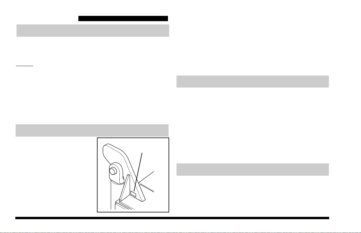
Replacement Parts
OH0280
MODEL & SERIAL
NUMBERS
IMPORTANT!
The replacement of any part on this product by anything
other than a Sky Trak authorized replacement part may
adversely affect the performance, durability, or safety of
this product and will void the warranty. Sky Trak assumes
no liability for unauthorized replacement parts which
adversely affect the performance, durability or safety of
this product.
Reports
IMPORTANT!
A Warranty Registration form must be filled out by the Sky
Trak distributor, signed by the purchaser, and returned to
Sky Trak once the product is sold and/or put into service.
This report activates the warranty period, assuring that
your claims during the warranty period will be honored and
processed expediently. To guarantee you full warranty
service, make sure your distributor has returned the
business reply card of this form to Sky Trak.
Disclaimer
Sky Trak reserves the right to make changes on and to
add improvements upon its products at any time without
public notice or obligation. Sky Trak also reserves the
right to discontinue manufacturing any product at its
discretion at any time.
For your easy reference
when ordering replacement
parts or making service in-
quiries on this machine, rec-
ord its model and serial num-
bers on the back cover of the
manual. The numbers are
stamped on the serial num-
ber plate which is located on
the front of the machine's
frame tilt cylinder tower.
Page 3
8042/10042 Rev. 10/99
Signal Word:
Is a distinctive word on safety decals and throughout this
manual that alerts the viewer to the existence and relative
degree of the hazard.
The signal word "Danger" means an extremely hazardous
situation exists on or near the
vehicle
which would result in
high probability of death or serious injury if proper precau-
tions are not taken.
The signal word “Warning” means a hazard exists on or
near the
vehicle
which can result in serious injury or death
if the proper precautions are not taken.
The signal word “Caution” is a reminder of safety practices
or directs attention to unsafe practices on or near the
vehicle
which could result in personal injury if the proper
precautions are not taken.
Danger
Warning
Caution
Safety Practices
The information in this manual does not replace any safety
rules and laws used in your area. Before operating this
telescopic handler, learn the rules and laws for your area.
Make sure the vehicle has the correct equipment according
to these rules and laws.
Your safety and the safety of others in the work area
depend significantly upon your knowledge and understand-
ing of all correct operating practices and procedures for this
vehicle.
Signal Words
This symbol means “Attention! Become Alert! Your
Safety Is Involved!” The symbol is used with the following
signal words to attract your attention to safety messages
found on safety decals and throughout this manual. The
message that follows the symbol contains important
information about Safety. To avoid possible death or
injury, carefully read and follow the messages! Be sure to
fully understand the potential causes of death or injury.

Page 4 8042/10042 Rev. 10/99
New or Additional Operators
At the time of original purchase, the purchaser of this
vehicle was instructed by the seller on its safe and correct
use. If this vehicle is to be used by an employee or is
loaned, rented or sold to someone other than the pur-
chaser, make certain that the new operator reads and
understands the Operator’s Manual and the Rough Terrain
Forklift Safety Manual that are provided with the vehicle
before operating the vehicle.
In addition, make sure that the new operator has com-
pleted a walk-around inspection of the vehicle, is familiar
with all decals and safety equipment on the vehicle, and
has demonstrated the correct use of all controls.
Personal Considerations
1. Seat Belt
Always adjust the seat and fasten the seat belt
securely before you start the engine.
2. Clothing and Safety Gear
DO NOT wear loose clothing or jewelry that can get
caught on controls or moving parts. Wear the
protective clothing and personal safety gear issued
or called for by job conditions.
MACHINE ROLL AWAY
MACHINE ROLL AWAY
can cause death or
serious injury.
ALWAYS engage
parking brake before
dismounting.
can cause death or
serious injury.
ALWAYS engage
parking brake before
dismounting.
WARNING
OG0400
3. Dismounting
DO NOT get off the vehicle until you:
• place the travel select lever in (N) Neutral,
• engage the emergency brake switch,
• lower the boom,
• ground the carriage,
• turn engine off,
• unbuckle the seat belt, and
• exit the vehicle using the hand holds.

Page 5
8042/10042 Rev. 10/99
•DO NOT use your hand to check for leaks.
Use a piece of cardboard or paper to search
for leaks. Wear gloves to protect hands from
spraying fluid.
• Hydraulic fluid can cause permanent eye
injury. Wear appropriate eye protection and
stop engine and relieve pressure before
disconnecting lines.
• If anyone is injured by or if any hydraulic fluid
is injected into the skin, obtain medical
attention immediately or gangrene may result.
D. Battery
The following WARNING is intended to supple-
ment and does not replace the warnings and
information provided on the battery by the
battery manufacturer.
4. Chemical Hazards
A. Exhaust Fumes
Fumes from the engine exhaust can cause
injury or death. If operating in an enclosed
area, provide good ventilation to replace
hazardous exhaust fumes with fresh air.
B. Explosive Fuel
Engine fuel is flammable and can cause a fire
and/or an explosion. Avoid danger by keeping
sparks, open flames and smoking materials
away from vehicle and fuel during refueling or
fuel system servicing. Know where fire extin-
guishers are kept on the work site and how to
use them.
C. Hydraulic Fluid
•DO NOT attempt to repair or tighten any
hydraulic hoses or fittings while the engine is
running or when the hydraulic system is under
pressure. Fluid in the hydraulic system is
under enough pressure that it can penetrate
the skin causing serious injury or death.
•HOT HYDRAULIC FLUID WILL CAUSE
SEVERE BURNS. Wait for fluid to cool down
before disconnecting lines.
OG0360
Page 6 8042/10042 Rev. 10/99
When jump starting the vehicle, carefully follow
instructions found under "Jump Starting" later in
this manual.
Keep sparks, flames, and lit cigarettes away
from battery at all times. Lead acid batteries
generate explosive gases. Severe chemical
burns can result from improper handling of
battery electrolyte. Wear safety glasses and
proper protective gear when handling batteries
to prevent electrolyte from coming in contact
with eyes, skin or clothing.
Battery Electrolyte First Aid
• External Contact — Flush with water.
• Eyes — Flush with water for at least 15
minutes and get medical attention
immediately!
• Internal Contact — Drink large quantities of
water. Follow with Milk of Magnesia, beaten
egg or vegetable oil. Get medical attention
immediately!
IMPORTANT: In case of internal contact, DO
NOT give fluids that would induce vomiting!
6. Lowering Boom or Falling Load Hazard
DO NOT get under a raised boom unless the boom is
blockedupsafely. Alwaysemptytheboomofanyload
and block up the boom before doing any servicing
which requires the boom to be raised.
NEVER allow anyone to walk or stand under a raised
boom. A lowering boom or falling load can result in
serious injury or death.
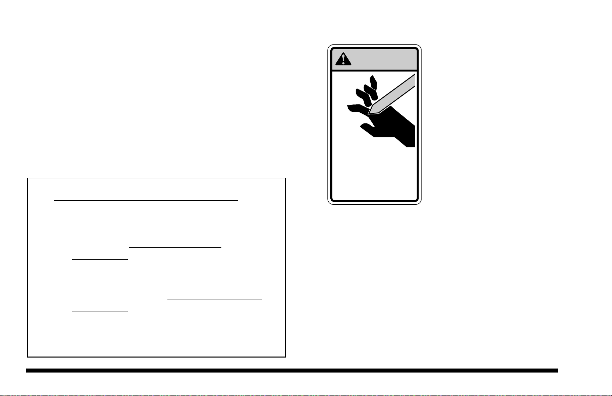
WARNING
MOVING PARTS can
cut off fingers or hands.
can
cut off fingers or hands.
Keep hands clear of
fans and belts while
engine is running.
Keep hands clear of
fans and belts while
engine is running.
OG0330
5. Moving Parts Hazard
DO NOT place limbs near
movingparts. Amputation of
any body part can result.
Turnoffengineandwaituntil
fan and belts stop moving
before servicing the vehicle.
Page 7
8042/10042 Rev. 10/99
OG0380
Prevent accidents when you move the vehicle
around the work site. Know the rules for movement
of people and vehicles on the work site. Follow the
instructions of signals and signs.
DO NOT operate the vehicle unless:
• all four tires are correctly filled with hydrofill,
• all safety equipment is in proper working condition,
• all covers and shields are in place, and
• all safety and instructional decals are in place and
readable.
(Replace all missing, illegible, or damaged decals.)
2. Clearances
Always check clearances carefully before driving
under electrical lines, bridges, etc.
3. Underground Hazards
Know the location of all underground hazards
before operating the vehicle in a new work area.
Electrical cables, gas pipes, water pipes, sewers, or
other underground objects can cause injury or
death. Contact your local underground utility
service or diggers' hotline to mark all underground
hazards.
Operational Considerations
1. Preparation and Prevention
Know the location and function of all vehicle controls.
Make sure all persons are away from the vehicle and
that the Travel Select Lever is in the "N" (Neutral)
position with the emergency brake switch engaged
before starting the engine.
Holes, obstructions, debris and other work area
hazards can cause injury or death. Always walk
around and look for these and other hazards before
operating the vehicle in a new work area.

Page 8 8042/10042 Rev. 10/99
5. Lifting Personnel
Use only an approved work platform for lifting and
lowering personnel. NEVER transport personnel in
a work platform for even the shortest distance.
Serious injury or death can occur if these rules are
not obeyed. Riders can fall and be crushed or run
over. Avoid accidents. For other specific precau-
tions, see "Elevating Personnel" later in this manual.
OG0341
OG0350
NEVER operate this vehicle in an area in which
overhead power lines, overhead or underground
cables, or power sources exist without first request-
ing that the appropriate power company or utility
company de-energize the lines or take other suitable
precautions.
4. Electrocution Hazard
Page 9
8042/10042 Rev. 10/99
6.Tip Over Hazard ALWAYS make sure that all four tires have been
properly filled with hydrofill by a qualified tire service
center.
Traveling with the boom raised is dangerous and can
cause tipover. Keep the load as low as possible.
Travel with extreme caution and at the slowest
possible speed.
Driving across a slope is dangerous, as unexpected
changes in the slope can cause tipover. Ascend or
descend slopes slowly and with caution.
Keep the vehicle under control at all times.
Avoid jerky turns, starts, or stops. Reduce operating
speed on rough ground and slopes.
Frame tilting with the boom raised above horizontal is
dangerous. Always use the frame tilt to level the
vehicle before raising the boom above horizontal, with
or without a load. If the vehicle cannot be leveled
using the frame tilt, reposition the vehicle.
If proper operating procedures are not followed,
this vehicle will tip over. If a vehicle ever becomes
unstable and starts to tip over,
• BRACE YOURSELF and STAY WITH THE
VEHICLE.
• KEEP SEAT BELT FASTENED,
• HOLD ON FIRMLY and
• LEAN AWAY FROM THE POINT OF IMPACT.
Indecision and trying to escape from a tipping vehicle
can result in death or injury.
DO NOT exceed the
rated lift capacity of the
vehicle, as structural
damage and unstable
vehicle conditions will
result.
OG0370

Page 10 8042/10042 Rev. 10/99
7. Slopes
DO NOT park the vehicle on an incline and leave it
unattended.
• Driving across a slope is dangerous, as
unexpected changes in the slope can cause
tipover. Ascend or descend slopes slowly and
with caution.
• Ascend or descend slopes with the heavy end of
the vehicle pointing up the slope.
NOTE: The rear of the vehicle is normally consid-
ered the heavy end unless the carriage is fully
loaded. In this case the front of the vehicle is now
the heavy end.
• Unloaded vehicles should be operated on all
slopes with the carriage pointing down the slope.
• On all slopes, the load must be tilted back and
raised only as far as necessary to clear the
ground.
• When operating on a downhill slope, reduce travel
speed and downshift to a low gear to permit
compression braking by the engine and aid the
application of the service brakes.
MACHINE TIPOVER can
result in death or serious
injury.
can
result in death or serious
injury.
Always operate machine
with rear stabilizer
cylinder in place and
functioning properly.
DANGER
OH0330
DO NOT remove or unpin the rear stabilizer cylinder
from the vehicle, as unstable vehicle conditions will
result.
ALWAYS be sure the Stabil-TRAK system is
functioning properly when operating the vehicle.
Refer to “Stabil-TRAK System Test” later in this
manual for proper system function.
Page 11
8042/10042 Rev. 10/99
Equipment Considerations
ALWAYS make sure that all four tires have been
properly filled with hydrofill by a qualified tire service
center. Improper hydrofill can cause instability
which can result in tipover.
8. Falling Load Hazard
DO NOT exceed the total rated load capacity of the
specific type fork being used. Each fork is stamped
with a maximum load capacity. If capacity is ex-
ceeded, forks may break. See "Fork Ratings" later
in this manual.
DO NOT downshift at a high ground speed. You
may drop the load off of the forks due to a sudden
slowing.
9. Visual Obstruction
Dust, smoke, fog, etc. can decrease vision and
cause an accident. Always stop or slow the vehicle
until the obstruction clears and the work area is
visible again.
10. Ventilation
Sparks from the electrical system and engine
exhaust can cause an explosion. DO NOT operate
this vehicle in an area with flammable dust or
vapors, unless good ventilation has removed the
hazard.
Carbon monoxide fumes from the engine exhaust
can also cause suffocation in an enclosed area.
Good ventilation is very important when operating
this vehicle.
Warning
DO NOT modify or repair (welding, drilling, etc.) any
part of this vehicle. Modifications can weaken the
structure creating a hazard that can cause injury or
death.

Page 12 8042/10042 Rev. 10/99
Operation
Steering Wheel (See Figure 1)
Turning the steering wheel to the left or right steers the
vehicle in the corresponding direction. Any one of three
steering modes are selectable. Refer to "Steering Select
Switch."
Controls
Ignition Switch (See Figure 1)
Using the ignition switch key, the switch may be turned
clockwise from the OFF position to the RUN and START
positions. The START position is spring-loaded to return
to the RUN position and must be manually held in place
for normal starting.
Off position — The entire electrical system is shut down.
Run position — All controls and indicators are operable.
Start position — Engages starter to crank the engine
when the emergency brake switch is engaged and the
transmission is in neutral.
Accelerator Pedal (See Figure 1)
Pressing down the accelerator pedal increases travel
speed of the vehicle. The pedal is spring-loaded to
return to idle speed.
Service Brake Pedal (See Figure 1)
Pressing down the brake pedal applies the wet disc
service brakes located in the axle wheel ends. It also
activates and locks the rear axle lock system when
OH0050
STEERING WHEEL
IGNITION SWITCH
SERVICE BRAKE PEDAL
ACCELERATOR PEDAL
boom angles are greater than 40°, as long as the pedal
is depressed.
Figure 1

Page 13
8042/10042 Rev. 10/99
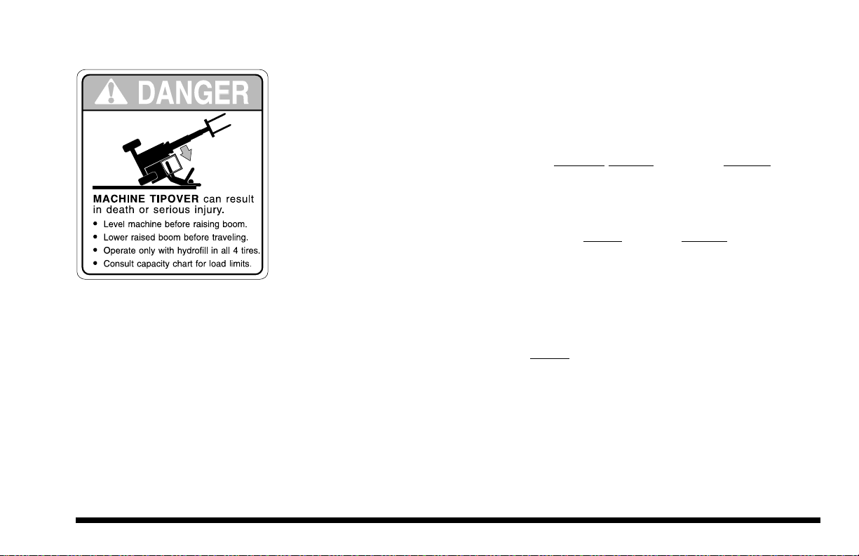
DANGER
MACHINE TIPOVER can result
in death or serious injury.
¥
Level machine before raising boom.
¥
Lower raised boom before traveling.
¥
Operate only with hydrofill in all 4 tires.
¥
Consult capacity chart for load limits.
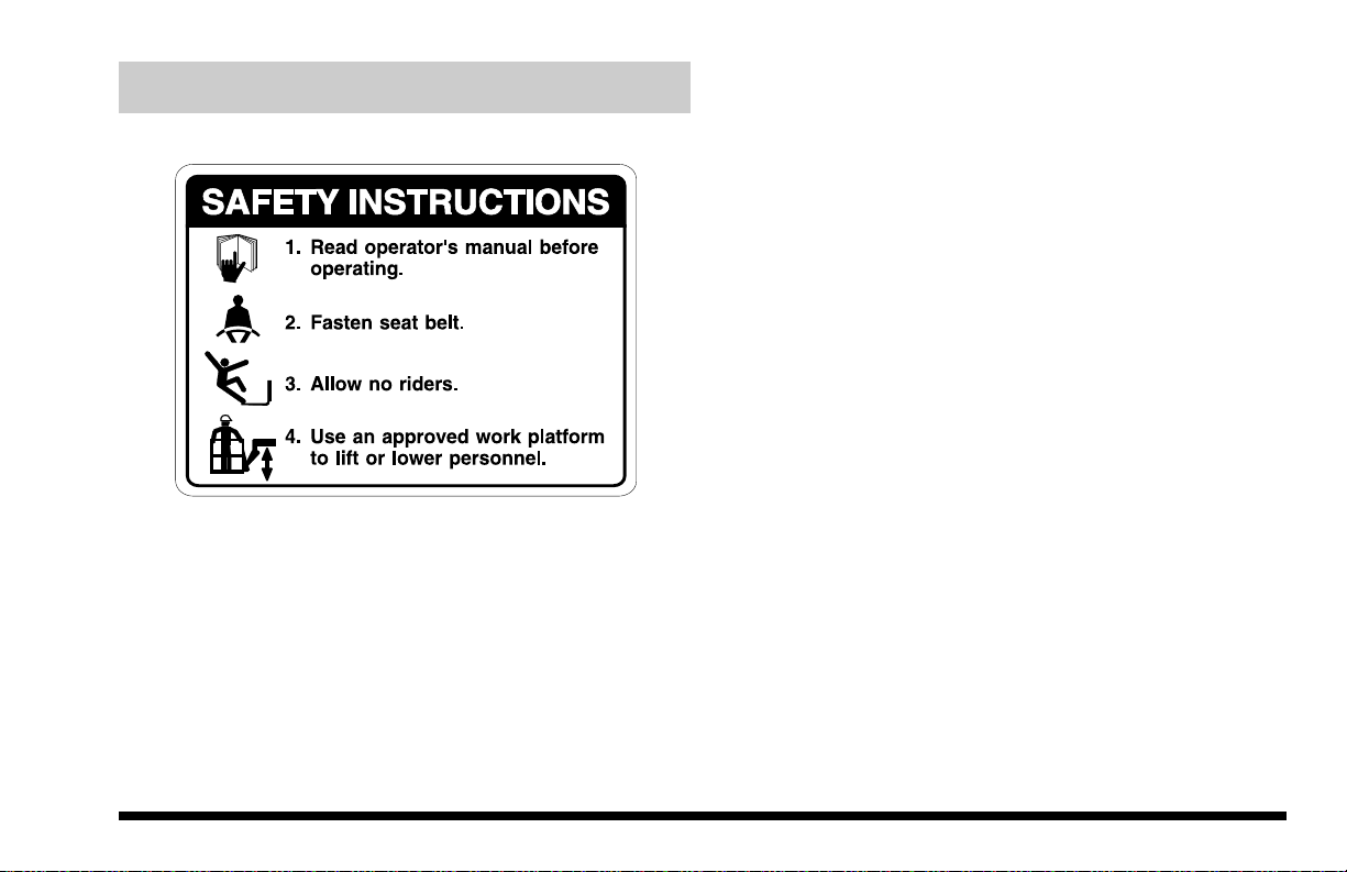
SAFETY INSTRUCTIONS
Read operator's manual before
operating.
Fasten seat belt.
Allow no riders.
Use an approved work platform
to lift or lower personnel.
1.
2.
3.
4.
LowerBoomBeforeExitingLoader
ReadOperatorsManual
FastenSeatBeltNoRiderss
WARNING
MACHINE ROLL
MACHINE ROLL
AWAY
can cause death or
can cause death or
serious injury
ous injury
.
ALWAYS
engage
parking brake before
parking brake before
dismounting.
EMERGENCY
BRAKE
P
P
CONTACTWITH ELECTRIC
POWER LINES can result in
electrocution.
Never operate this machine within
10 feet of electric power lines.
Notify the power company to
de-energize the lines before
operating forklift.
DANGER
Steering Select Switch (See Figure 2)
This switch has three positions:
Four Wheel Steer ....up position
Two Wheel Steer.....center position
Crab Steer...............down position
RefertoSteeringunder"Operating"fordetailedinformation.
EMERGENCY
BRAKE SWITCH OH0045
TRAVEL SELECT
LEVER STEERING
SELECT SWITCH
RANGE
SELECT LEVER
Travel Select Lever (See Figure 2)
The travel select lever has three positions to select
direction of travel:
F= Forward........ all the way up
N= Neutral ......... center position
R= Reverse ....... all the way down
When the travel select lever is shifted into REVERSE, the
back-up alarm will automatically sound.
NOTE: The travel select lever must be in NEUTRAL to per-
mit engine starting and when boom angles are greater than
40°, shifting into NEUTRAL locks the Stabil-TRAK system.
Figure 2
P
P
Emergency Brake Switch (See Figure 2)
The
emergency
brake switch has two positions:
Engaged ...............lift red switch cover then
push switch up
Disengaged .......... lower red switch cover
The emergency brake must be ENGAGED to permit engine
starting. Operator should use caution when engaging the
emergency brake while vehicle is moving, because the
stop will be abrupt and operator may be jolted forward unex-
pectedly. The emergency brake may be used to stop in an
emergency situation. With boom angles greater than 40°,
this switch activates and locks the Stabil-TRAK system.
OG0390
OH0780
HORN
BUTTON

Page 14 8042/10042 Rev. 10/99
Range Select Lever (See Figure 2)
The range select lever has three positions to select the
gear range:
1= Low .............. all the way down
2= Medium ........ center position
3= High.............. all the way up
Use first gear for highest torque and pulling power. Use
third gear for highest ground speed.
Boom Control Lever (See Figure 3)
The boom control lever is a joystick with variable motion
from the center to control the boom functions:
OH0170
0H0360
BOOM CONTROL
LEVER
ATTACHMENT AND
FRAME TILT
CONTROL
LEVER
Figure 3
Two boom functions can be accomplished at the same
time by moving the lever into the proper quadrant. For
example: moving the lever forward and to the left will
lower and retract the boom simultaneously.
The speed of boom movement depends on the amount
of lever movement in the corresponding direction. The
overall speed of movement depends directly upon the
speed of the engine.
Boom Raise ....... move lever backward
Boom Lower....... move lever forward
Boom Extend ..... move lever to the right
Boom Retract ..... move lever to the left

Page 15
8042/10042 Rev. 10/99
Attachment and Frame Tilt Control Lever
(See Figure 3)
The attachment and frame tilt control is a joystick with
four perpendicular motions from the center to control
two attachment functions and two frame tilt functions:
Frame Tilt Left ...............move lever to the left
Frame Tilt Right.............move lever to the right
Attachment Tilt Down ....move lever forward
Attachment Tilt Up.........move lever backward
OH0410
The attachment is self leveling and will retain any set
angle throughout boom raising, lowering, retracting or
extending operations.
OH0360
Figure 4
OUTRIGGER
CONTROL
SWITCHES
Outrigger Control Switches (std. 10042 only)
(See Figure 4)
The left and right outrigger control switches raise or
lower the corresponding outriggers.
OH0420
Raise Left Outrigger ........... lift switch up
Lower Left Outrigger........... push switch down
Raise Right Outrigger......... lift switch up
Lower Right Outrigger ........ push switch down

Page 16 8042/10042 Rev. 10/99
IMPORTANT! Outrigger equipped vehicles can be used
with the outriggers in either the raised or lowered position.
The operator must operate the vehicle within the limits
specified on the appropriate capacity chart for the
outrigger position.
Procedure for Lowering of Outriggers
Secure and proper outrigger placement is critical for
stability of the vehicle. Avoid holes or drop-offs and soft or
excessively uneven terrain. Lower outriggers just far
enough until the front of the vehicle starts to raise and
maintain a level position. Use the following procedure to
assure that both outriggers have been lowered securely.
IMPORTANT: For optimum vehicle stability, never lower
the outriggers to the point at which the tires come com-
pletely off the ground.
1. Before locating the vehicle at the lift point, observe that
the landing area for the outriggers is free of loose
material or debris and that the terrain appears to be
solid and free of holes.
2. Position the vehicle at the lift point and level the
vehicle to zero degrees (0°). If the vehicle cannot be
leveled, reposition the vehicle.
3. Lower the right outrigger until the right front tire just
starts to raise and maintains this position.
4. Lower the left outrigger until the left front tire just starts
to raise and again maintains this position.
5. Frame tilt the vehicle back to level (0°) if necessary.
Horn Button (Figure 2)
Pressing the momentary-contact horn button sounds the
vehicle horn.
Circulation Fan (Enclosed Cab Only)
(Not Pictured)
The circulation fan is only operable when the ignition
switch in is the RUN position. The fan switch is located
at the base of the fan mount.
Sliding Windows (Enclosed Cab Only)
(Not Pictured)
The sliding windows are latched with a combination slide
bar and squeeze actuated latch.
Page 17
8042/10042 Rev. 10/99
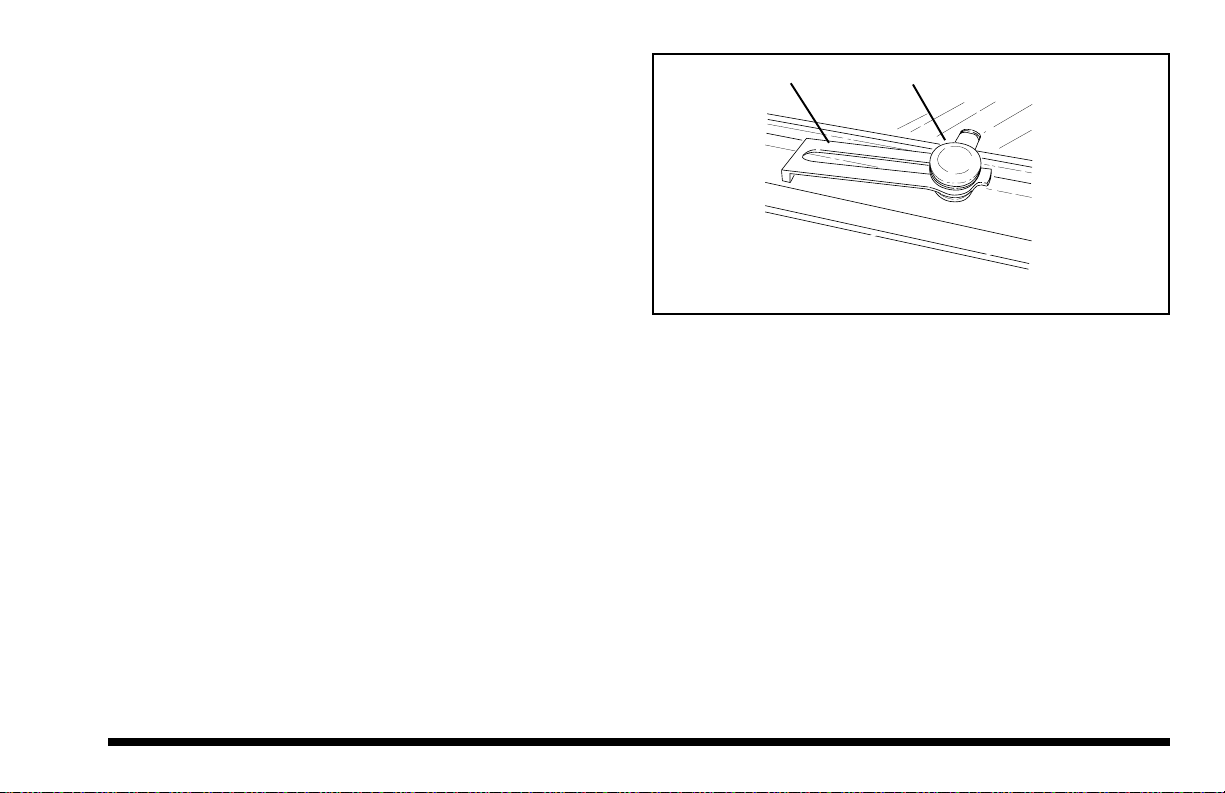
PIVOT ARM KNOB
OA0052
Figure 5
Windshield Washer/Wiper Control
(Enclosed Cab Only) (Not Pictured)
Turn the knob counterclockwise to operate the wipers at
low speed; turn the knob clockwise to operate the
wipers at high speed. Pressing the knob activates the
windshield washer for as long as it is held in. The
windshield washer fluid tank is located to the rear of the
right console (early models) or it is the front tank next to
the seat support (later models).
Rear Window Control (Enclosed Cab Only)
(See Figure 5)
Loosen the knob and slide the pivot arm in the slot to
open the rear window. Tighten the knob to secure.
Reverse the procedure to close the window.
NOTE: The rear window can be used as an emergency
exit if necessary. Unscrew the knob from the stud, raise
the pivot arm over the stud, and push the window out.
Door Latches (Enclosed Cab Only)
(Not Pictured)
There are two door latches. The outside latch is a key
lockable pull to release type. The inside latch is a push
to release type.
Roof Washer/Wiper Control
(Enclosed Cab Only) (Not Pictured)
Turn the knob clockwise to operate the wiper. Pressing
the knob activates the roof washer for as long as it is
held in. The washer fluid tank is the rear tank located
next to the seat support.

Page 18 8042/10042 Rev. 10/99
Cab Heater (Enclosed Cab Only)
(See Figure 6)
The cab heater fan is only operable when the ignition
switch is in the RUN position. The heater fan switch is
located on the left side of the seat base (Figure 6). The
switch has three positions: OFF, LO, and HI.
NOTE: During warm weather operation, close the heater
line shut-off valve, located in the heater hose connection
at the engine. (Valve is located below engine alternator.)
Seat Belt (See Figure 6)
The seat belt has a slide on each strap that is used to
tighten and loosen the strap on each side of the buckle.
To shorten, pull bottom of loop toward buckle. To
lengthen, hold slide strap, pull slide toward buckle and
readjust buckle on loop. Buckle the two straps together
to fasten. Lift the buckle latch or press the center button
to unfasten the seat belt.
Operator's Seat Adjustment (See Figure 6)
The position and suspension of the operator's seat can
be adjusted.
Suspension — Turn the knob on the front of the seat to
adjust suspension stiffness for operator weight.
Height — Height adjustment is achieved by grasping the
bottom of the seat and raising upward into one of the
three detent positions. Once the seat has reached the
highest detent position, it can be lowered by raising the
seat all the way and lowering it fully. The seat can then
be raised, one detent at a time to the desired height.
Forward/Backward — Release the lever on the left side
of the seat and slide seat forward or backward to suit.
SEAT
BELT
FORWARD/
BACKWARD
LEVER
HEATER
CONTROL
CAB HEATER
SUSPENSION
ADJUST KNOB
Figure 6 OA0071
This manual suits for next models
1
Table of contents
Other Skytrak Lifting System manuals

Popular Lifting System manuals by other brands

Adaptive Engineering
Adaptive Engineering AX Operation and maintenance manual

Amico
Amico Go Lift Portable 450 Installation and operation instructions

Jungheinrich
Jungheinrich EFG 316 operating instructions

harbor master
harbor master Premier Verical Lift instructions

GSi
GSi PNEG-1295 installation manual

XPOtool
XPOtool 30120 user manual


