Skyworth SLTV-1551A-1 User manual

15 LCD Television / Monitor
Owner s Manual
SLTV-1551A-1
SLTV-1551AW-1

RISK OF ELECTRIC SHOCK
DO NOT OPEN
WARNING
WARNING: TO REDUCE THE RISK OF ELECTRIC SHOCK DO NOT
REMOVE COVER OR BACK. NO USER-SERVICEABLE PARTS INSIDE.
REFER SERVICING TO QUALIFIED SERVICE PERSONNEL.
The lighting flash with arrow head within a
triangle is intended to tell the user that parts
inside the product are a risk of electric shock
to persons.
The exclamation point within a triangle is
intended to tell the user that important
operating and servicing instructions are in
the papers with the appliance.
WARNING: To reduce the risk of electric shock do not expose this apparatus to rain or moisture and objects
filled with liquids, such as vases, should not be placed on this apparatus.
IMPORTANT SAFETY INSTRUCTIONS
1.READ INSTRUCTIONS - All the safety and operating
instructions should be read before the unit is operated.
2.RETAIN INSTRUCTIONS - The safety and operating
instructions should be retained for future reference.
3.HEED WARNINGS - All warnings on the unit and in
the operating instructions should be adhered to.
4.FOLLOW INSTRUCTIONS - All operating and use
instructions should be followed.
5.CLEANING - Unplug this unit from the wall outlet
before cleaning. Do not use liquid cleaners or aerosol
cleaners. Use a damp cloth for cleaning the exterior
cabinet only.
6.ATTACHMENTS - The manufacturer of this unit
does not make any recommendations for attachments,
as they may cause hazards.
7.WATER AND MOISTURE - Do not use this unit near
water. For example, near a bathtub, washbowl,
kitchen sink, laundry tub, in a wet basement, or near a
swimming pool.
8.ACCESSORIES - Do not place this unit on an
unstable cart, stand, tripod, bracket, or table.
The unit may fall, causing serious injury, and serious
damage to the unit. An appliance and cart
combination should be moved with care. Quick stops,
excessive force, and uneven surfaces may cause the
appliance and cart combination to overturn.
TV/CATV MODE SELECTION
When shipped from the factory, the TV/CATV menu option is set to the TV mode. If using CATV, set the
menu option to CATV (Cable Television)
PORTABLE CART WARNING
9.VENTILATION - Slots and openings in the cabinet
back or bottom are provided for ventilation, to
ensure reliable operation of the unit and to protect it
from overheating. These openings should never be
blocked by placing the unit on a bed, sofa, rug, or
other similar surface. This unit should never be
placed near or over a radiator or heat source. This
unit should not be placed in a built-in installation,
such as a bookcase, or rack unless proper ventilation
is provided or the manufacture s instructions have
been adhered to.
10.POWER SOURCE - This unit should be operated
only from the type of power source indicated on the
rating plate. If you are not sure of the type of power
supply to your home, consult your appliance dealer
or local power company. For units intended to
operate from battery power, or other sources, refer
to the operating instructions.
,
CAUTION
Changes or modifications not expressly approved by the party responsible for compliance with the FCC
Rules could void the use s authority to operate this equipment.
,
1
S3126A
WARNING:
WARNING:Do not leave any stationary images, patterns, PIP box, or letterbox images on the screen foran extended
period of time. Also, do not display the same stationary patterns frequently. This may result in permanent
ghost images on the display unit. This type of damage is not covered under warranty. Examples of this
type of situation can be but not limited to the following: side bar images, stock market report bars, video
game patterns, closed captioning, shopping channel logo, price display, and letterbox black bars. To
prevent this type of damage, display constant moving images that fill the screen as often as possible.
According to theindustrial standards, there are a certainnumber of defective pixels both bright
and dark that are acceptable. Although we produce panel with more than 99.99 percent active
cells, there stillmay be some cells that donot produce light or remain lit. For more information,
please contact salesor the technical support.

11.POLARIZATION - This unit is equipped with a
polarized alternating current line plug (a plug
having one blade wider than the other). This plug
will fit into the power outlet only one way. This is
a safety feature. If you are unable to insert the
plug fully into the outlet, try reversing the plug. If
the plug still fails to fit, contact your electrician to
replace your obsolete outlet. Do not defeat the
safety purpose ofthe polarized plug.
12.POWER-CORD PROTECTION - Power supply
cords should be routed so that they are not likely
to be walked on or pinched by items placed upon
or against them, paying particular attention to
cords at plugs, convenience receptacles, and the
point where theyexit from the appliance.
13.LIGHTNING - To protect your unit during a
lightning storm, or when it is left unattended and
unused for long periods of time, unplug it from
the wall outlet and disconnect the antenna or
cable system. This will prevent damage to the unit
due to lightningand power line surges.
14. POWER LINES - An outside antenna system
should not be located in the vicinity of overhead
power lines, or other electric light or power
circuits, or where it can fall into such power lines
or circuits. When installing an outside antenna
system, extreme care should be taken to keep
from touching such power lines or circuits as
contact with them might be fatal.
15.OVERLOADING - Do not overload wall outlets
and extension cords as this can result in a risk of
fire or electric shock.
16.OBJECT AND LIQUID ENTRY - Do not push
objects through any openings in this unit as they
may touch dangerous voltage points or short out
parts that could result in fire or electric shock.
Never spill orspray any type of liquid intothe unit.
17.OUTDOOR ANTENNA GROUNDING - If a n
outside antenna or cable system is connected to
the unit, be sure the antenna or cable system is
grounded to provide some protection against
voltage surges and built-up static charges.
Section 810 of the National Electrical Code,
ANSI/NFPA 70, provides information with respect
to proper grounding of the mast and supporting
structure, grounding of the lead-in wire to an
antenna discharge unit, size of grounding
conductors, location of antenna discharge unit,
connection to grounding electrodes, and
requirements for thegrounding electrode.
18.SERVICING - Do not attempt to service this
unit yourself as opening or removing covers may
expose you to dangerous voltage or other
hazards. Refer all servicing to qualified service
personnel.
19.DAMAGE REQUIRING SERVICE- Unplug this
unit from thewall outlet and refer servicing to
qualified service personnelunder the following
conditions:
A. When the power-supply cord or plugis
damaged.
B. If liquidhas been spilled, or objects have fallen
into the unit.
C. If theunit has been exposed to rain or water.
D. If the unit does not operate normally by
following the operatinginstructions. Adjust
only those controlsthat are coveredby the
operating instructions, asan improper
adjustment of other controls may result in
damage and will often require extensive work
by a qualifiedtechnician to restorethe unit to
Its normal operation.
E. If theunit has been dropped or the cabinet has
been damaged.
F. When the unit exhibits a distinct change in
performance, this indicatesa need forservice.
20.REPLACEMENT PARTS- When replacement
parts are required, be sure the service technician
uses replacement parts specified by the
manufacturer or those that have the same
characteristics as the original part. Unauthorized
substitutions may result in fire, electric shock or
other hazards.
21.SAFETY CHECK - Upon completion of any
service or repairs to this unit, ask the service
technician to perform safety checks to determine
that the unitis in proper operating condition.
22.HEAT - The product should be situated away
from heat sources such as radiators, heat
registers, stoves, or other products(including
amplifiers) that produceheat.
23.NOTE TO CATV SYSTEM INSTALLER - This
reminder is provided to call the CATV system
installer s attention to Article 820-40 of the NEC
that provides guidelines for proper grounding and,
In particular, specifies that the cable ground shall
be connected to the grounding system of the
building, as close to the point of cable entry as
practical.
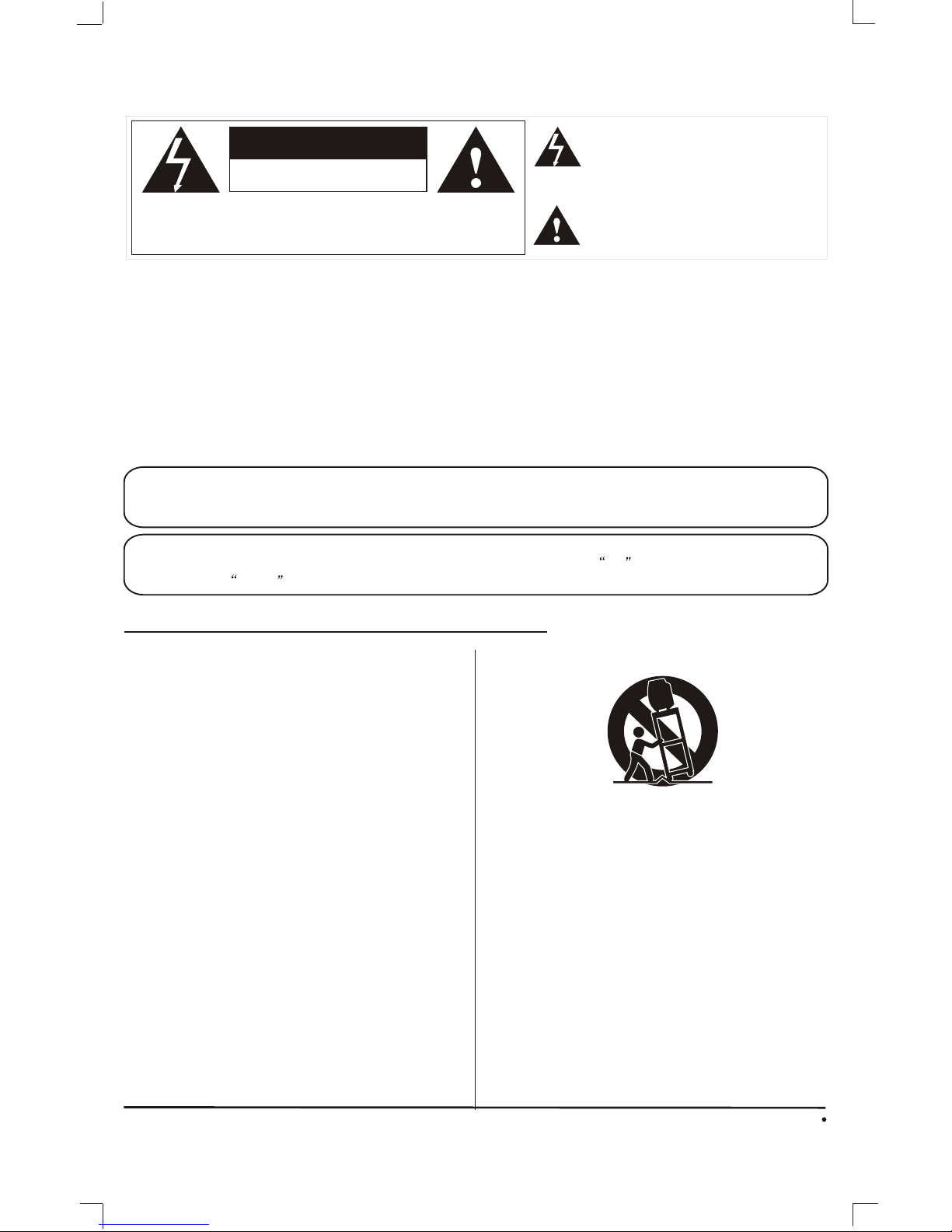
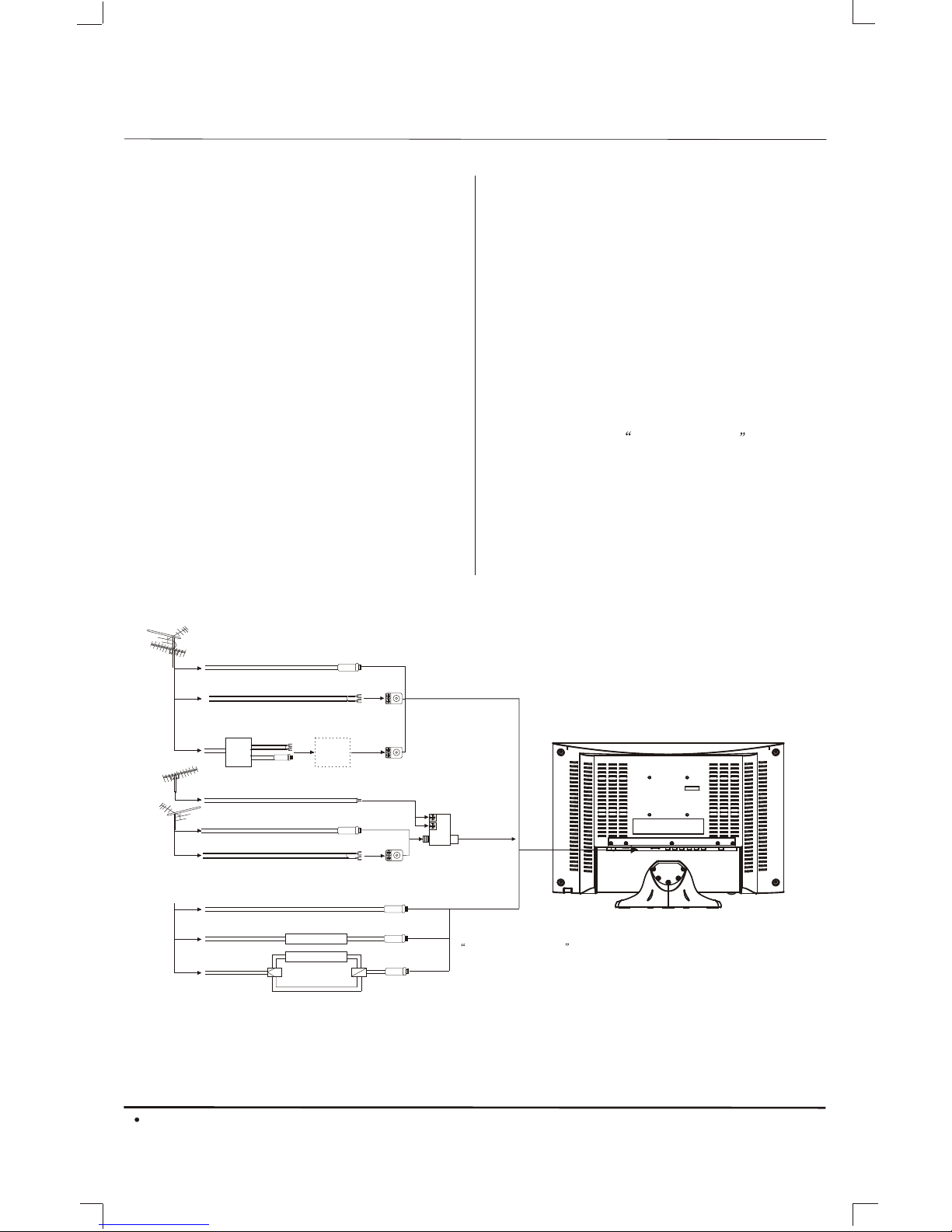
GROUNDING CONDUCTORS
(NEC SECTION 810-21)
ANTENNA DISCHARGE UNIT
(NEC SECTION 810-20)
ANTENNA LEAD
IN WIRE
GROUND
CLAMP
ELECTRIC
SERVICE
EQUIPMENT
GROUND CLAMPS
POWER SERVICE GROUNDING
ELECTRODE SYSTEM
(NEC ART 250. PART H)
NEC - NATIONAL ELECTRIC CODE
EXAMPLE OF ANTENNA GROUNDING AS PER
NATIONAL ELECTRICAL CODE S2898A
2
,

TABLE OF CONTENTS
Table of Contents
Congratulations
Specifications
Installation
Television Location
Power Source
Combination VHF/UHF Antenna
Remote Control Battery Installation
Optional Equipment Connections
Rear Panel Connectors
Front Control Panel
Function Menu Operation
PICTURE
AUDIO
TIME
OPTION
CHANNEL
Service Tips
4
4
5
5
5
5
6
7
7
7
Remote Control Operation 8-12
11-13
11
11
11
11
13
3
14
Limited Warranty 15-16
TV mode 8-10
LOCK 12

¼ò ½é¼ò ½é
Congratulations
You new TV Monitor/Receiver features a solid state chassis that is designed to give you man years of enjoy
ment. It wasthoroughly tested and tuned at the factory for bestperformance.
CONGRATULATIONS
4
Note:
Specification are subject to change without prior notice.
15 Color (Diagonal)
1024 x 768
NTSC/ATSC
; ATSC
< 1W
4:3
On/Off/CC on Mute
for Video and S-video
for YPbPr
PC AUDIO X 1
20-1/220-1/2 XX 7-1/87-1/8 XX15-3/1615-3/163/163/16 pp
18-1/8 X 6-7/8 X12-15/16p18-1/8 X 6-7/8 X12-15/16p
6-13/166-13/16
10-1/810-1/8
YesBuild inDTV

INSTALLATION
Installation
Television Location
Follow these recommendations before deciding the
location of your television.
Avoid excessive sunlight or bright lights,
including reflections.
Keep away from excessive heat or moisture.
Inadequate ventilation may cause internal
component failure.
Fluorescent lighting may reduce remote
control transmitting range.
Keep away from magnetic equipment,
including motors, fans and external speakers.
WARNING: Use this television receiver only with the
cart, stand, tripod, bracket, or table specified by the
manufacturer, or sold with the apparatus. When a cart
is used, use caution when moving the Cart / apparatus
combination to avoid injury from tip-over. In order to
avoid injury to children, never place your television
receiver on a piece of furniture that is capable of being
tilted by a child leaning on it, pulling on it, standing o it,
or climbing on it. A falling television can cause serious
injury or even death.
Remote Control Battery Installation
Requires two AAA batteries(supplied).
Procedure
1. Turn the remote control face down. Remove battery
cover by pressing down on the marking on the
cover and sliding it off in the direction indicated.
2. Install batteries matching(+) and(-) polarity signs.
3. Replace the battery cover by sliding in reverse until
the lock snaps.
Note: Incorrect installation can cause battery leakage
and corrosion that will damage the Remote
control.
Precautions
Replace batteries in pair.
Do not mix battery types(zinc carbon with
alkaline).
Do not recharge, heat, short-circuit,
disassemble, or burn batteries.
5
NOTE:
1.AC/ DC adaptor provided can be connected to
the specified voltage (AC 110 volts 60HZ).
2.If the polarized AC cord does not fit into a non-
polarized AC outlet, do not attempt to file or cut
the blade. It is the user s responsibility to have
an electrician replace the obsolete outlet.
3.If you cause a static discharge when touching
the unit, and the unit fails to function, simply
unplug the unit from the AC outlet, wait a few
minutes, and plug it back in. The unit should
return to normal operation.
,
POWER SOURCE
TO USE AC POWER SOURCE
Use the AC /DV adaptor provided for operation on AC.
Insert the AC cord plug into a standard 110-120V 60HZ
polarized AC outlet.
AC outlet
Wider Hole
and Blade
Polarized AC CordPlug (One
blade is widerthan the other)
To use Car cord
Use the Car Cord provided for operation on 12V DC.
Make sure thearrow on plug is aligned with the
small gap onthe socket.

INSTALLATION
Combination VHF/UHF Antenna
Combination VHF/UHF Antenna (Single 75 ohm
cable or 300 ohm twin-lead wire)
Connect the 75 ohm cable from a combination
VHF/UHF antenna to the antenna jack.
Combination VHF/UHF Antenna (Separate VHF and
UHF 300 ohm twin-lead)
Connect the UHF twin-lead wire to a combiner (not
supplied). Connect the VHF twin-lead to the 300-75
ohm matching transformer (not supplied). Attach the
transformer to the combiner. Attach the combiner to
the antenna jack.
Separate VHF/UHF Antenna
Connect the 75 ohm cable from the VHF antenna and
the UHF antenna twin-lead to a combiner (not
supplied). Attach the combiner to the antenna jack.
NOTE: If your VHF antenna has a twin-lead wire, use
the 300-75 ohm matching transformer( not supplied),
then connect the transformer to the combiner.
For Subscribers to Scrambled Cable TV service
If you subscribe to a cable service which requires the
use of a converter/descrambler box, connect the
incoming cable to the converter/descrambler box and
connect the output of the box to the antenna jack on
the back of the television. Follow the connections
shown left. Set the television to the output of the
converter/descrambler box (usually channel 3 or 4)
and use the converter / descrambler box to select
channels.
For Subscribers to Unscrambled Basic Cable with
Scrambled Premium Channels
If you subscribe to a cable service in which basic
cable channels are unscrambled and premium
channels require the use of a converter/descrambler
box, you may wish to use a two-set signal splitter (
sometimes called a two-set coupler )and an A/B
switch box from the cable installer or an electronics
supply store. Follow the connections shown left. With
the switch in the B position, you can directly tune
any nonscrambled channels on your TV. With the
switch in the A position, tune your TV to the output
of the converter/descrambler box (usually channel 3
or 4) and use the box to tune scrambled channels.
6
Combination VHF/UHF Antenna
Single 75 ohm cable
300 ohm twin-lead wire
Splitter
Take off the Splitter
300-75 OHM MATCHING
TRANSFORMER
(not supplied)
UHF Antenna
300 ohm twin-lead wire
VHF Antenna
Single 75 ohm cable
300 ohm twin-lead wire
300-75 OHM MATCHING
TRANSFORMER
(not supplied)
COMBINER
(not supplied)
Incoming CATV
Converter/Descrambler
Splitter A/B Switch A B
This television has an extended tuning range and can tune
most cable channels without using a cable company
supplied converter box. Some cable companies offer
premium pay channels in which the signal is scrambled.
Descrambling these signals for normal viewing requires the
use of a descrambler device which is generally provided by
the cable company.
For Subscribers to Basic Cable TV Service
For basic cable service not requiring a converter/
descrambler box, connect the CATV 75 ohm coaxial
cable directly to the antenna jack on the back of the
television.

BASIC CONTROLS AND CONNECTIONS
Optional Equipment Connections
Procedure
Connect equipment as shown to Audio/Video
input jacks.
Select the Video mode by pressing TV/AV
button.
Operate optional equipment as instructed in
equipment manual.
Front Control Panel
The front control panel can be used to access
menus and switch video mode when the remote control
is not available.
Note: The ON/OFF indicator LED(red) will light up
when you insert the AC cord into the AC outlet.
7
Headphone jack: Plug an earphone or monaural
headphones into this jack for private listening.
Side Panel Connectors
1. DC 12V In
2. Headphone Jack
3. PC Audio In
4. PC In
5. Component In
6. Video In
7.Video / S-Video Audio In
8. S-Video In
9. Antenna or cable In
10. Component Audio In
123456789
10
1. Remote Sensor
2. TV/AV Button
3. Mute Button
4. Menu Button
5. CH.+ Button
6. CH.- Button
7. VOL.+ Button
8. VOL.- Button
9. Power Indicator / Power Button
DC IN HEADPHONE PC AUDIO IN VGA YPb
COMPONENT AUDIO IN 1
Pr VIDEO RLS-VIDEO ANT IN
L
AUDIO IN 2
R
1
2
3
4
5
6
7
8
9

»ù±¾²Ù×÷»ù±¾²Ù×÷
REMOTE CONTROL OPERATION
Remote Control Operation
8
Turn on / off.
POWER
Back to previous viewed channel.
RECALL
Multichannel Television Sound.
MTS
Set the sleep timer.
Mute the sound.
MUTE
Select channel or enter password.
1
2
3
4
5
6
7
8
9
0
-/---/--
Display information of current input.
Select desired picture mode.
Select sound mode.
Enter CC setting menu.
Select channel digits.
DISPLAY
CC
PICTURE
SLEEP
SOUND -/---/--
++
VOL.+VOL.-
AV/TV
ENTER
CH.+
MENU
CH.-
EXIT
EPG
MTS RECALL CC
ZOOM PICTURE SOUND
CH.LIST FAV.LIST
SLEEP
Display the channlelist.
CH.LIST
MENU
Display menu function.
Channels Up / Down.
Volume Up / Down
Display the favoriteprogram list.
FAV. LIST
Electronic program guide.
EPG
Enter the selecteditem.
Escape from the current operation.
EXIT
Select the screensize.
ZOOM
Switch to desired input source.
AV/TV
ENTER
VOL.+VOL.-
CH.+
MENU
CH.-

REMOTE CONTROL OPERATION
9
TV MODE:
1.POWER Button( )
Press this button to turnthe TV on or intostandby mode.
2.MUTE Button
Press this button to mutethe sound and the signof mute
will appear all the whileif you do not pressagain.
But the sign of mute will disappear if the CCD is displayed.
3.SLEEP Button
Press this button to setthe sleep timer. When thepreset
length of time has passed, the TV set enters standby
mode. The sleep timer values are follows: off, 15¡¢ 30¡¢
60¡¢90¡¢ 120¡¢180¡¢240 minutes.
4.SOUND Button
Press this button to selectdesired sound mode. Four
sound modes are available including Standard, Music,
Movie and Personal.
5.PICTURE Button
Press this button to selectdesired picture mode. Four
picture modes are available includingStandard, Soft,
Dynamic and Personal.
6.RECALL Button
Press this button to watchthe previously viewed
channel for both ATV and DTV.
7.MTS Button
When stereo program is received,press this button to
switch sound system between monoand stereo. When
SAP program is received, press this button to switch
sound system between mono andSAP. When stereo
and SAP program is received, press this button to switch
among mono, stereo and SAP.
8.CC Button
Press this button to select the CC Mode. Three CC Mode
are available including On, CC on Mute and off.
9.DISPLAY Button
Press this button to displaythe information on current
input.
10.NUMBER (0-9)Buttons
Press these buttons to enter digits. These buttons for
direct access to use achannel to enter channel number
for both ATV and DTV or enter password forV-Chip.
2
19
17
10
1
15
14
918
7
3
-/---/--
++
VOL.+VOL.-
AV/TV
ENTER
CH.+
MENU
CH.-
EXIT
EPG
MTS RECALL CC
ZOOM PICTURE SOUND
CH.LIST FAV.LIST
SLEEP
4
13
16
5
6
8
21
20
11 12

REMOTE CONTROL OPERATION
10
11.-/-- Button
In TV mode, pressthis button and input the channel
number which you wantto select.
12.AV/TV Button
Press this button todisplay the input source such as
TV, AV, S-Video, COMPONENTand PC. Using
UP/DOWN button select itemand press RIGHT or
ENTER button to enter selected item.
13 CH. LIST Button
Press this button todisplay the channel list in TV mode.
14.VOLUME+/VOLUME- (V+/V-) Buttons
Press these buttons toincrease or decrease the volume.
15.CHANNEL+/CHANNEL- (CH+/CH-) buttons
Press these buttons toselect channels in ascending
or descending order.
16.FAVORITE LIST (FAV.LIST) Button
Press this button todisplay the favorite program list
17.MENU Button
Press this button toenter the menu mode for various
optional adjustable settings orquit from current menu.
18.ELECTRONIC PROGRAM GUIDE(EPG) Button
Press this button tocall up the Electronic Program Guide.
19.ENTER Button
Press this button toenter the selected item.
20.EXIT Button
Press this button toescape from the current operation.
21.ZOOM Button
Press this button toselect the screen size, such as Full,
Zoom and Cinema .
2
19
17
10
1
15
14
918
7
3
-/---/--
++
VOL.+VOL.-
AV/TV
ENTER
CH.+
MENU
CH.-
EXIT
EPG
MTS RECALL CC
ZOOM PICTURE SOUND
CH.LIST FAV.LIST
SLEEP
4
13
16
5
6
8
21
20
11 12

Function Menu Operation
Press MENU buttonto display main menu picture.
You can browsePICTURE, AUDIO, TIME, OPTION,
LOCK and CHANNELmenu by pressing LIFT/RIGHT
buttons. Press UP/DOWNbuttons to enter the
selected menu andadjust available setting by
pressing LIFT/RIGHT buttons.
Note: when adjustingavailable setting completed,
please wait fora moment, and the TV set will enter
the main menupicture for restoring.
AUDIO menu
In PICTURE menu,you can press UP/DOWN buttons
to select availableitems and adjust or select Picture
Mode, Contrast, Brightness, Sharpness, Tint, Color,
Color Mode andZoom Mode by pressing LIFT/RIGHT
buttons.
Note:
¡ñTint is only available for NTSC system.
¡ñTint and Colorare not available for PC mode.
In AUDIO menu,you can press UP/DOWN buttons to
select available itemsand adjust Bass, Treble and
Balance by pressingLIFT/RIGHT buttons.
Press the LIFT/RIGHTbuttons to select the Sound
Mode. The choicesare Standard, Music, Movie and
personal.
Press the LIFT/RIGHT buttons to select the Audio
Language. The choicesare English, French and
Spanish.
Press the LIFT/RIGHTbuttons to select the MTS.
The choices areSAP, MONO and STEREO.
TIME menu
In TIME menu, you can press UP/DOWN buttons to
select items.
In Sleep Timer items, you can select to turn off or
on the sleep time setting.
In Time Zone items, you can select the time zone,
the choices are Eastern, Central, Mountain, Pacific,
Alaska and Hawaii.
In Daylight Saving Time items, you can select to
on or off it.
OPTION menu
You can changesome basic settings of the TV set
in this menu. Press UP/DOWN buttons to select
available items in this menu and perform
corresponding operation.
OSD Language
Multi-Language OSD issupported by thisTV set.
You can selectdesired OSD language by pressing
LIFT/RIGHT buttons.
Transparency
To change the OSD style, you can select to turn on
or off theTransparency.
Picture menu
AUDIO TIME OPTION LOCK
PICTURE CHANNEL
Picture Mode
Contrast
Brightness
Tint
77
Color
63
46
Color Mode
Zoom Mode
Personal
Normal
Sharpness
Full
0
60
AUDIO TIME OPTION LOCK
PICTURE CHANNEL
Sound Mode
Bass
Treble
Balance 0
Audio Language
50
50
MTS
Standard
English
Stereo
AUDIO TIME OPTION LOCK
PICTURE CHANNEL
Sleep Timer
Time Zone
Daylight Saving Time
Off
Eastern
Off
PC Set Up
Enter this item; you can select to adjust H-Pos,
V-Pos, Clock andPhase items to suitable value.
If you selectAuto item, the TV set will start adjust
PC settings automatically. It will take a few seconds
to finish theadjustment including horizontal and
vertical position, phaseand clock of the PC image.
AUDIO TIME OPTION LOCK
PICTURE CHANNEL
H-Pos
V-Pos
Clock
Phase 100
Auto
50
50
50
AUDIO TIME OPTION LOCK
PICTURE CHANNEL
OSD Language
Transparency
PC Set Up
Closed Caption
English
Restore Default
Off
11

Function Menu Operation
Closed Caption
Enter this item; you can change CC Mode, Basic
Selection, Advanced Selection and Option by
pressing LIFT/RIGHT buttons.
Press LIFT/RIGHT buttonsto change the CC Mode.
The choices areon, off and CC on Mute.
Press LIFT/RIGHT buttons to change the Basic
Selection. The choicesare CC1, CC2, CC3, CC4,
Text1, Text2, Text3and Text4.
Press LIFT/RIGHT buttonsto change the Advanced
Selection. The choicesare Service1, Senvice2,
Senvice3, Senvice4, Senvice5and Senvice6.
Enter Option item,you can change the CC style as
you like by adjust the items.
Restore Default
Press RIGHT buttonto reset TV settings with
default value. It is strongly recommended that you
should scan TVprograms right after reset TV
settings.
Note:
¡ñBasic Selection is only available for NTSC system.
¡ñAdvanced Selection and Option is only available
for ATSC system.
LOCK menu
You can setV-Chip in this menu. All settings are
effective for bothATV and DTV.
Enter Password
The default V-Chip password is1111.
Change Password
To change password, you need to enter the old
password. After enterold password, you can enter
the new password and confirm password, which
consists of onlydigitals. The new password and
on firm passwordmust be same. If the new
password and confirmpassword are different,
unmatched is displayedto indicate that new
password is invalidand press ENTER button to
enter new password.
System Lock
Press LIFT/RIGHT buttonsto change the system
lock. The choices are on and off.
AUDIO TIME OPTION LOCK
PICTURE CHANNEL
----
Enter Password
AUDIO TIME OPTION LOCK
PICTURE CHANNEL
Change Password
System Lock
US
Canada
RRT Setting
On
Reset RRT
AUDIO TIME OPTION LOCK
PICTURE CHANNEL
Enter Old Password
Enter New Password
Confirm Password
----
----
----
US
Enter US menu,you can select to change TV and
MPAA setting.
AUDIO TIME OPTION LOCK
PICTURE CHANNEL
TV
MPAA NC-17
Canada
Enter Canada menu,you can select to change
Canada Eng andCanada Fre setting.
AUDIO TIME OPTION LOCK
PICTURE CHANNEL
Canada Eng
Canada Fre 8ans+
C8+
TV
AUDIO TIME OPTION LOCK
PICTURE CHANNEL
TV TATING
ALL FV VSLD
TV-Y
TV-Y7
TV-G
TV-PG
TV-14
TV-MA
:Block
AUDIO TIME OPTION LOCK
PICTURE CHANNEL
CC Mode
Basic Selection
Advanced Selection
Option
On
CC1
Service1
12

Function Menu Operation
Enter TV RATING menu, you can use the direction
buttons to select desired rating and use ENTER
button to lock or unlock the items.
MPAA
In this menu,you can set MPAA rating. Press LIFT
/RIGHT button toselect desired item. The choices
are N/A, G, PG, PG-13, R, NC-17 and X.
Canada Eng
In this menu,you can set Canada English rating.
Press LIFT/RIGHT button to select desired item.
The choices are E, C, C8+, G,PG, 14+ and 18+.
Canada Fre
In this menu,you can set Canada French rating.
Press LIFT/RIGHT button to select desired item.
The choices areE, G, 8ans+, 13ans+, 16ans+
and 18ans+.
RRT Setting
Enter this menuto set the Rating Region Table.
Reset RRT
This item isused to reset the rating region table.
CHANNEL menu
The last menu is CHANNEL menu. You can select
Antenna, Auto Scan, Favorite, Channel Skip,
Channel No., Channel Label and DTV Signal.
Antenna
In this menu,you can select the antenna mode.
The choices are Cable and Air.
Auto Scan
Enter this menu, you can press the RIGHT button
to start theauto scan. It takes a few minutes to
search and store all available programs
automatically. During theauto scan process,
please do notterminate it by turning off the TV set.
Otherwise the program information may not be
stored. For cable signal, you can select the Cable
System. The choices are AUTO,STD, IRC and HRC.
Favorite
This menu enables you to create a favourete list
with your preferredTV channels. Enter this menu,
press ENTER buttonto add or delete a favorite
program in thelist.
Channel Skip
Enter this menu, press ENTER button to enable or
disable the current program being tuned.
AUDIO TIME OPTION LOCK
PICTURE CHANNEL
Antenna
Auto Scan
Favorite
Channel Skip
Channel Label
DTV Signal
Cable
5-0
Channel No.
Channel No.
Press LIFT/RIGHT buttonto decrease or increase
the channel number.
Channel Label
Enter this menu, you can edit the program name
by using LIFT/RIGHTbutton to select and using
UP/DOWN button toedit the name.
DTV Signal
This menu showsyou the signal quality of DTV.
13

»ù±¾²Ù×÷»ù±¾²Ù×÷
Service Tips
Service Tips
Please make these simple checks as
indicated ( ) on the chart for the
respective symptoms and their possible
remedies.
No picture, no sound
Poor sound, picture OK
Poor picture, sound OK
Weak picture
Blurred picture
Double image
Lines in picture
Distorted picture
Weak reception on some channels
Horizontal bars
Picture rolls vertically
Poor colour
No colour
Misoperation of Remote control
Remote control unit no operation
On Screen Display Control outside the screen
Try differentchannel, if OK,probablystation trouble
Check aerial connections on backof set
Check aerial for broken wires
Re-orientaerial (if indoor type)
Probably local interference, such asanappliance
Adjustfine tuningcontrol
Adjust brightnesscontrol
Adjust contrast control
Check if station is broadcasting colour
Adjustcolourcontrol
Check ifsystem is correctly set
Checkifon/offswitch is "on"
Check batteriesin remotecontrol unit
Possible Remedies
Symptoms
14

15

8M28
16
This manual suits for next models
1
Table of contents
Other Skyworth LCD TV manuals

Skyworth
Skyworth SLTV-1963A User manual

Skyworth
Skyworth LCD-32L16 User manual

Skyworth
Skyworth LCD-42L29-FHD User manual

Skyworth
Skyworth SLTV-2632A-2 User manual

Skyworth
Skyworth SLTV-1963A-1 User manual

Skyworth
Skyworth LCD-26L16 User manual

Skyworth
Skyworth 19E57 User manual

Skyworth
Skyworth 39e36 User manual

Skyworth
Skyworth 6M61S User manual

Skyworth
Skyworth LCD-32L29 User manual