Slee MICROTOME CUT 6062 User manual

DESIGN &
MANUFACTURING
MADE IN GERMANY
MICROTOME
CUT 6062
FULLYAUTOMATIC
ROTARY MICROTOME
O P E R A T I N G
M A N U A L


Manual_CUT_6062_2021-10-008.00_EN.docx 3
CONTENTS
1INTENDED USE _______________________________________________________ 5
2SYMBOLS____________________________________________________________ 5
3SAFETY NOTES _______________________________________________________ 5
3.1 HAND WHEEL STOP 6
3.2 FINGER PROTECTION GUARD 8
3.3 ELECTRICAL CONNECTIONS 9
3.4 EMERGENCY SWITCH 10
3.5 MOTORIZED OPERATION 10
3.6 WORKING WITH KNIVES AND DISPOSABLE BLADES 10
4COMPONENTS ______________________________________________________ 11
4.1 MAGNIFIER WITH ILLUMINATION, DIMMABLE (OPTIONAL) 12
5SPECIFICATIONS_____________________________________________________ 15
6UNPACKING AND INSTALLATION _____________________________________ 17
6.1 UNPACKING THE DEVICE 17
6.2 INSTALLATION 17
7OPERATION OF CUT 6062 ____________________________________________ 18
7.1 INSERTION OF SPECIMEN IN STANDARD SPECIMEN CLAMP 18
7.2 INSERTION OF SPECIMEN IN UNIVERSAL CASSETTE CLAMP 19
7.3 SPECIMEN ORIENTATION ADJUSTMENT 20
7.4 EXCHANGING THE CLAMP TYPE 21
7.5 INSERTION AND ORIENTATION OF MICROTOME KNIVES 26
7.6 INSERTION AND ORIENTATION OF DISPOSABLE BLADES 27
7.7 APPROACH TO SPECIMEN 32
7.8 SPECIMEN FEED MEMORY 33
7.9 MOTORISED COARSE ADVANCE 33
7.10 MOTORISED FINE ADVANCE 33
7.11 MANUAL CUTTING 34
7.12 ADJUSTMENT OF TRIMMING 35
7.13 ADJUSTMENT OF CUTTING 35

4 Manual_CUT_6062_2021-10-008.00_EN.docx
7.14 ROCKING MODUS 35
7.15 ADJUSTMENT OF RETRACTION DURING THE UPWARD MOVEMENT 36
7.16 SECTION COUNTER / SECTION SUM / REMAINING TRAVEL INDICATION 37
7.17 DISPLAY CONTRAST SETTINGS 37
7.18 SETTING OF CUTTING SPEED 38
7.19 SETTING OF TRIMMING SPEED 39
7.20 SETTING OF CUTTING MODE 40
7.21 PROGRAMMING AUTOMATIC CUTTING 42
7.22 OVERVIEW KEY COMBINATIONS 43
8EXTERNAL CONTROL PANEL CUT 6062 ________________________________ 45
8.1 EXTERNAL CONTROL PANEL CUT 6062 45
8.2 FUNCTIONAL OVERVIEW OF USER INTERFACE 46
9CLEANING AND MAINTENANCE ______________________________________ 47
9.1 CLEANING 47
9.2 RECOMMENDED MAINTENANCE AND SERVICE SCHEDULE 47
10 SERVICE ____________________________________________________________ 48
11 OPTIONAL ACCESSORIES_____________________________________________ 49
12 WARRANTY_________________________________________________________ 50
13 DISPOSAL __________________________________________________________ 50

Manual_CUT_6062_2021-10-008.00_EN.docx 5
1INTENDED USE
The rotary microtome CUT 6062 is intended for cutting thin sections of soft paraffin-embedded and harder specimens for
professional use in routine and research laboratories in the fields of biology, medicine and industry.
The system of specimen advance operates very reliable from 0.5 to 100 µm. The quality of cutting of this microtome is
increased by the automatic retraction during the upstroke of the specimen, which avoids rubbing on the disposable blades
or microtome knives. This stops rapid deterioration of the disposable blade or microtome knife.
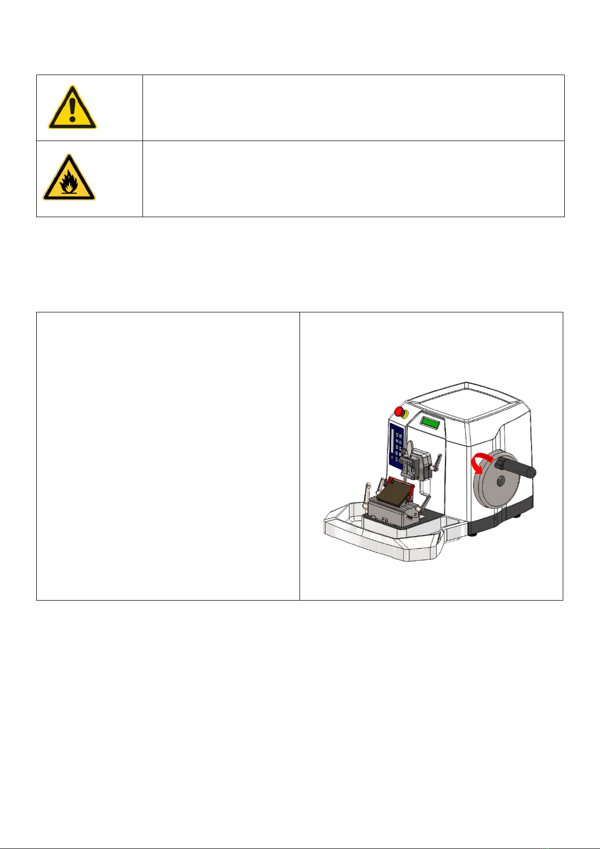
2SYMBOLS
Slee rotary microtomes are provided with the following safety features:
CUT 6062
Hand wheel stop •
Collapsible hand wheel lever •
Emergency stop switch •
Finger protection guard for knife- or blade-holder •
The institution which owns the unit and the persons working with the unit, servicing or repairing it have the responsibility
for a hazard-free use.
Dangers, warnings and cautions are marked by this symbol.
This symbol indicates possible fire hazards.
iSpecial instructions regarding the operation of the device are marked by this symbol.
Mechanical components that can lead to injuries during operation are marked with this symbol.
6 Manual_CUT_6062_2021-10-008.00_EN.docx
MAGNIFIER WITH LIGHTING (OPTIONAL)
3.1 HAND WHEEL STOP
3.1.1 HAND WHEEL STOP WITH BRAKE ON THE HANDLE
Always use the finger protection guard with the knife- /
blade holder and put hand wheel in stop position
•before working with the knife or specimen,
•before changing the specimen,
•during break time.
The hand wheel can be stopped in any position. For this
purpose, move stop towards the center. To do this, turn the
locking lever 90° counterclockwise.
To release the handwheel lock again, turn the lever 90°
clockwise.
For motorized operation with CUT 6062 please always fold
the hand wheel lever to the inside into the recess provided.
To do this pull the handle to the outside and then fold it to
the inside. Once you move it back again it will automatically
latch on again.
Risk of glare and injury! Never look into the sun or any other bright light source with
optical devices! Do not look directly into the light source.
Fire hazard! Lenses in optical devices can cause considerable damage due to the "burn-
ing glass effect" if improperly handled or stored! Make sure that optical lenses are
never left in the sun without a cover!
Use the supplied cover!

Manual_CUT_6062_2021-10-008.00_EN.docx 7
3.1.2 HANDWHEEL STOP WITH BRAKE ON THE BASE (OPTIONAL)
Always use the finger protection guard with the knife- /
blade holder and put hand wheel in stop position
•before working with the knife or specimen,
•before changing the specimen,
•during break time.
The basic brake can be activated in every handwheel posi-
tion. To close, turn the lever for 90° clockwise vertically
(notch).
Basic brake open
To release the handwheel lock, turn the lever 90° counter-
clockwise.
Basic brake closed

8 Manual_CUT_6062_2021-10-008.00_EN.docx
3.2 FINGER PROTECTION GUARD
Use the finger protection guard for the blade and knife
holder as well as the handwheel stop always
•before you start any work with the knife or spec-
imen,
•before changing the specimen,
•during work break.
Finger protection guard released
Finger protection guard activated
i
Please note that the finger protection guard may be engaged throughout processing (exchange
of blade, lateral displacement, trimming, cutting), thereby increasing operation safety!
Do never move your fingers or hands above or behind the blade holder during operation of the
microtome. For loading and unloading of the sample holders and exchange of disposable blades
in the disposable blade holder, always activate the handwheel lock and activate the finger pro-
tection guard.
Manual_CUT_6062_2021-10-008.00_EN.docx 9
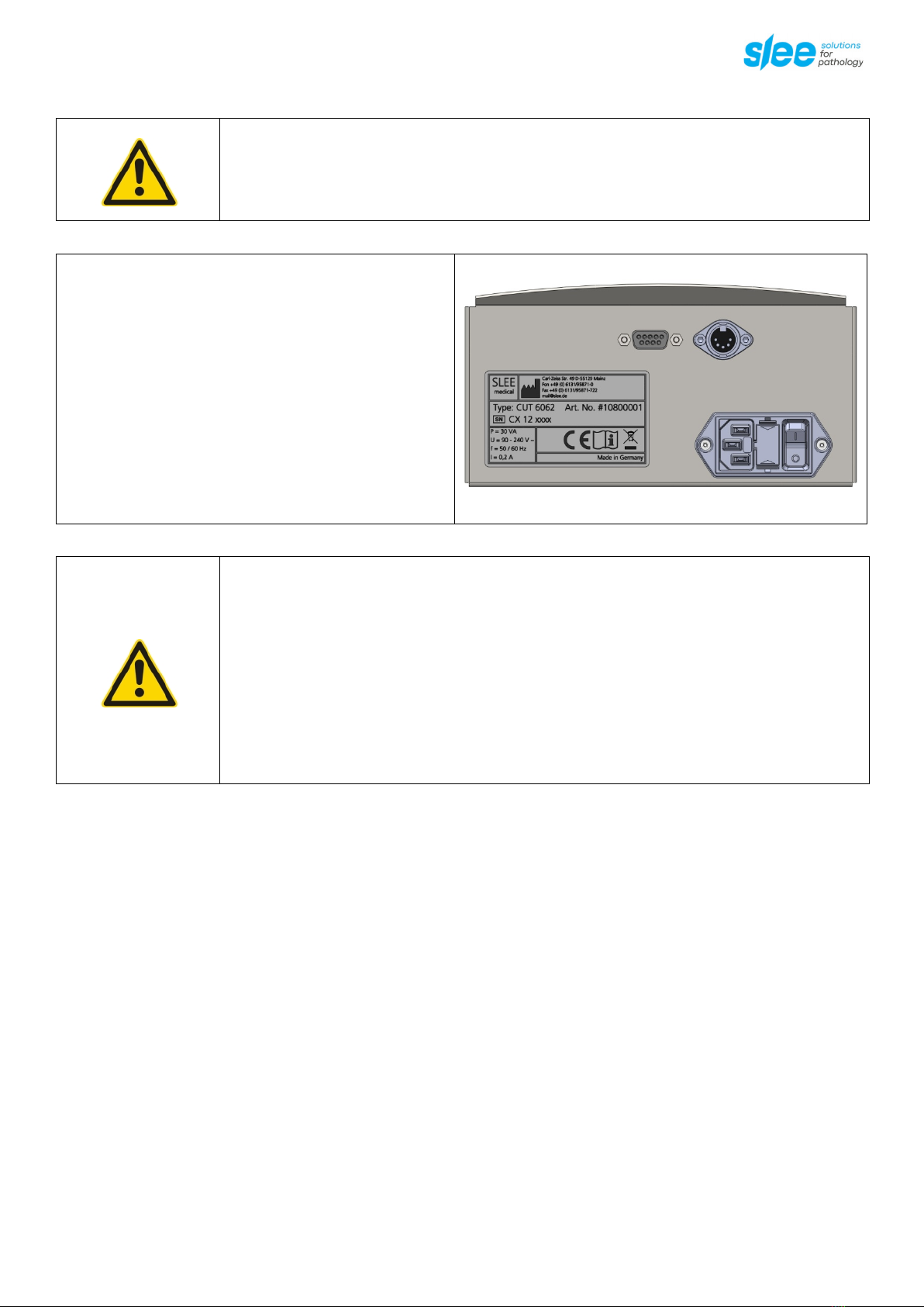
3.3 ELECTRICAL CONNECTIONS
Electrical connections are attached at the backside of the
microtome. Further on the name plate is located here (pos.
1).
Following connections are available depending on the mi-
crotome type:
2: External Control Panel
3: Footswitch
4: Mains cable
5: Fuse
6: ON- / OFF-Switch
Before connecting any electrical units, the device must be switched off.
•Before installing the device, check that the electrical connection values correspond to
the specifications on the type plate and that a constant power supply is guaranteed. This
should be examined during installation of the unit by a competent person.
•Do not use any extension cable.
•For maintenance and service always unplug the mains cable.
•Only use a specified fuse for the unit.
•Do not connect another unit to the same power circuit.
2
3
4
6
5
1

10 Manual_CUT_6062_2021-10-008.00_EN.docx
3.4 EMERGENCY SWITCH
By pressing the red emergency switch an emergency stop is
activated. The cutting motor stops immediately.
For deactivating the emergency stop it has to be turned,
then it moves automatically back into the original position.
The device switches on again automatically. The motor re-
mains switched off for safety reasons and must be switched
on and started again for operation.
3.5 MOTORIZED OPERATION
To switch the motor on and off, use the control button on the left side of the unit or the installed foot switch.
3.6 WORKING WITH KNIVES AND DISPOSABLE BLADES
Microtome knives and disposable blades have extremely sharp edges and this can lead to injuries. Please be extremely careful
when handling microtome knives and disposable blades.
Do not place microtome knives or disposable blades at unsecured areas. Never position micro-
tome knives or disposable blades with the sharp edge pointing upwards.
Store blades in a covered container. Use a container that has guides to hold the blades rigid.
Never try to catch a falling microtome knife.
Always insert the specimen first and then the microtome knife or disposable blade.
When applying the brake, ensure that it is tight. Most accidents occur when the brake slips and
the operator’s hand is drawn into the blade.
To avoid compression or knife marks, ensure that the blade is clean.
In case of multiple use of the knife or blade, use the finger guard.
To increase the usage time of knives and blades, avoid increased wear and tear by cleaning the
cutting edge and blade holder regularly.

Manual_CUT_6062_2021-10-008.00_EN.docx 11
4COMPONENTS
Slee rotary microtomes are provided with the following standard components:
CUT 6062, #10080001
Specimen orientation •
Universal cassette clamp, orientable, alternatively standard specimen clamp, orientable •
3-component knife holder, can be used for low profile blades as well as high profile blades •
Section waste tray •
Disposable blades (low profile, 50 pcs.), optional with disposable blades (high profile, 50
pcs.) or microtome knife 16 cm C-profile
•
Dust cover •
Allen key, for fixation of specimen orientation to microtome •
Foot switch for motor drive •
Mains cable •
Manual •

12 Manual_CUT_6062_2021-10-008.00_EN.docx
4.1 MAGNIFIER WITH ILLUMINATION, DIMMABLE (OPTIONAL)
Mounting:
The ring magnifier with illumination can easily be at-
tached to the side of the microtome's base plate.
2 M5x12 countersunk screws (supplied) are screwed into
the base plate from below.

Manual_CUT_6062_2021-10-008.00_EN.docx 13
Switching on / off:
The light can be switched on and off via the sensor switch
on the light head.
Switching on: Touch the sensor for a brief moment -> the
light will be switched on (switch-on value is the last dim-
ming value).
Switching off: Touch the sensor again for a brief moment
-> the light will be switched off.
Dimming: Touch the sensor until the desired brightness is
obtained. To reverse the dimming direction, briefly inter-
rupt touching the sensor.
Note:
The illumination is equipped with overheating protection. In case the luminaire is switched off because of a risk of overheat-
ing, the luminaire must be cooled down, before being put back into operation.
Warning: Fire hazard!
When not in use, cover the magnifier against solar radiation. To do this, use the bag in-
cluded in the scope of delivery.

14 Manual_CUT_6062_2021-10-008.00_EN.docx
Specifications magnifier with illumination:
Protection class II
Protection type IP 20
Operating mode Continuous operation
Technical safety check EN 60 598-1
Light head ca. Ø 122 x 13 mm
Magnifier 6.0 dpt. approx. Ø 72
Rated voltage 100 - 240 V AC
Frequency range 50/60 Hz
Power consumption approx. 6 W

Manual_CUT_6062_2021-10-008.00_EN.docx 15
5SPECIFICATIONS
Nominal supply voltage 100 - 240 V + / -10 %
Nominal frequency 50/60 Hz
Power draw 120 VA
Protective class (1) I
Power fuses 2 x T 1,6 A
Pollution degree (1) 2
Overvoltage installation category II
Maximum heat emission 120 J / s
Operating temperature range +10 to +35 °C
Operating humidity max. rel. 80 % non-condensing
Storage temperature range +5 to +55 °C
Storage humidity max. rel. 80 % non-condensing
Section thickness range 0.5 - 100 µm
Section thickness settings 0.5 - 2 µm in 0.5-µm steps
2 - 20 µm in 1-µm steps
20 - 50 µm in 2-µm steps
50 - 100 µm in 5-µm steps
Trimming thickness settings 0 - 750 µm
0.5 - 2 µm in 0.5-µm steps
2 - 20 µm in 1-µm steps
20 - 50 µm in 2-µm steps
50 - 150 µm in 5-µm steps
150 - 750 µm in 10-µm steps
Horizontal advance 28 mm (step motor)
Specimen feed speed SLOW 75 / 150 / 300 / 600 µm / s
Specimen feed speed normally 3.000 µm / s
Specimen feed memory 2 positions programmable
Vertical specimen stroke 72 mm
Maximum specimen size 50 x 50 mm
Sectioning speed 3 - 450 mm / s selectable via slider
Sectioning modes Continuous, Single, Rocking, Window, Program
Sectioning window 4 sizes selectable
Knife holder basis - north-south axis 35 mm
Specimen retraction on return stroke 0 - 200 µm, selectable
Specimen orientation, horizontal 8°
Specimen orientation, vertical 8°

16 Manual_CUT_6062_2021-10-008.00_EN.docx
Specimen orientation, z-axis 360°
Section counter Strokes / Distance
Dimensions [width x depth x height] 520 mm x 600 mm x 325 mm incl. handwheel and waste tray
Weight without accessories 34 kg
(1) According to IEC 1010, EN 61010

Manual_CUT_6062_2021-10-008.00_EN.docx 17
6UNPACKING AND INSTALLATION
6.1 UNPACKING THE DEVICE
Remove the upper wooden cover.
Remove the upper supporting foams.
Lift the device out of the wooden transportation case.
Grasp the device underneath the base plate from the rear and front as shown in the figure below.
Save the packaging material for later transport purposes, as the microtome should be transported in its original packaging
to avoid transport damage.
Set up the microtome at its destination.
6.2 INSTALLATION
The unit should be positioned onto a plane, vibration-free surface.
Before use remove the transport security underneath the specimen head.
Assure convenient and unobstructed access to the hand wheel. Do not cover the ventilation outlet on the backside of the
device and keep a minimum distance between wall and rear of the device of 5 - 10 cm.
Connect the foot switch for the cutting motor and the external control panel [optional] with the outlet on the back of the
device. Connect the device to the power supply.
For connection of electric devices, please consider the guidance’s listed in 3.3 ELECTRICAL CONNECTIONS.
i
Do not transport the device by holding it on the hand wheel shaft, the object head, the cover or
the tray.

18 Manual_CUT_6062_2021-10-008.00_EN.docx
7OPERATION OF CUT 6062
7.1 INSERTION OF SPECIMEN IN STANDARD SPECIMEN CLAMP
Turn the handwheel to the highest position and activate the
handwheel lock (see chapter 3.1) and the finger guard.
Loosen the standard specimen clamp by turning the fixing
screw counterclockwise.
Remove the old specimen or insert a new one.
Loosening of object fixation and insertion of new object
Close the specimen clamp and fix the specimen by turning
the clamping screw (see fig.) clockwise.
Loosen the finger guard and the handwheel lock (see chap-
ter 3.1) to cut the specimen.
Closing of specimen clamp and fastening of object fixation
If the cassette is clamped horizontally (rotated 90°), it is rec-
ommended to use the supplied clamping block (item no.
34123507) to re-center the cassette. If the cassette is nor-
mally clamped vertically, this additional clamping block is
not used.
In order to bring the specimens closer to the middle section,
the clamping block must be clamped to the upper cheek.
Clamping block
Additional note:
In case you process exceptionally hard specimens, the required clamping force may not be achieved by simply tightening the
clamping screw. For these exceptional cases, an attachment for an open-end wrench SW17 is provided in the middle area
of the clamping screw. We would like to point out that very high clamping forces can occur when using tools and this can
lead to increased wear on the corresponding components.
Manual_CUT_6062_2021-10-008.00_EN.docx 19
7.2 INSERTION OF SPECIMEN IN UNIVERSAL CASSETTE CLAMP
Turn hand wheel to its highest position and activate the
hand wheel lock.
Activate finger protection guard.
Open cassette fixation by pulling the fixation lever.
Insert / remove cassette.
Object fixation will go back into fixation position automati-
cally.
Release finger protection guard and hand wheel lock (see
chapter 3.1) for cutting.
Opening of cassette fixation and insertion of new cassette
20 Manual_CUT_6062_2021-10-008.00_EN.docx
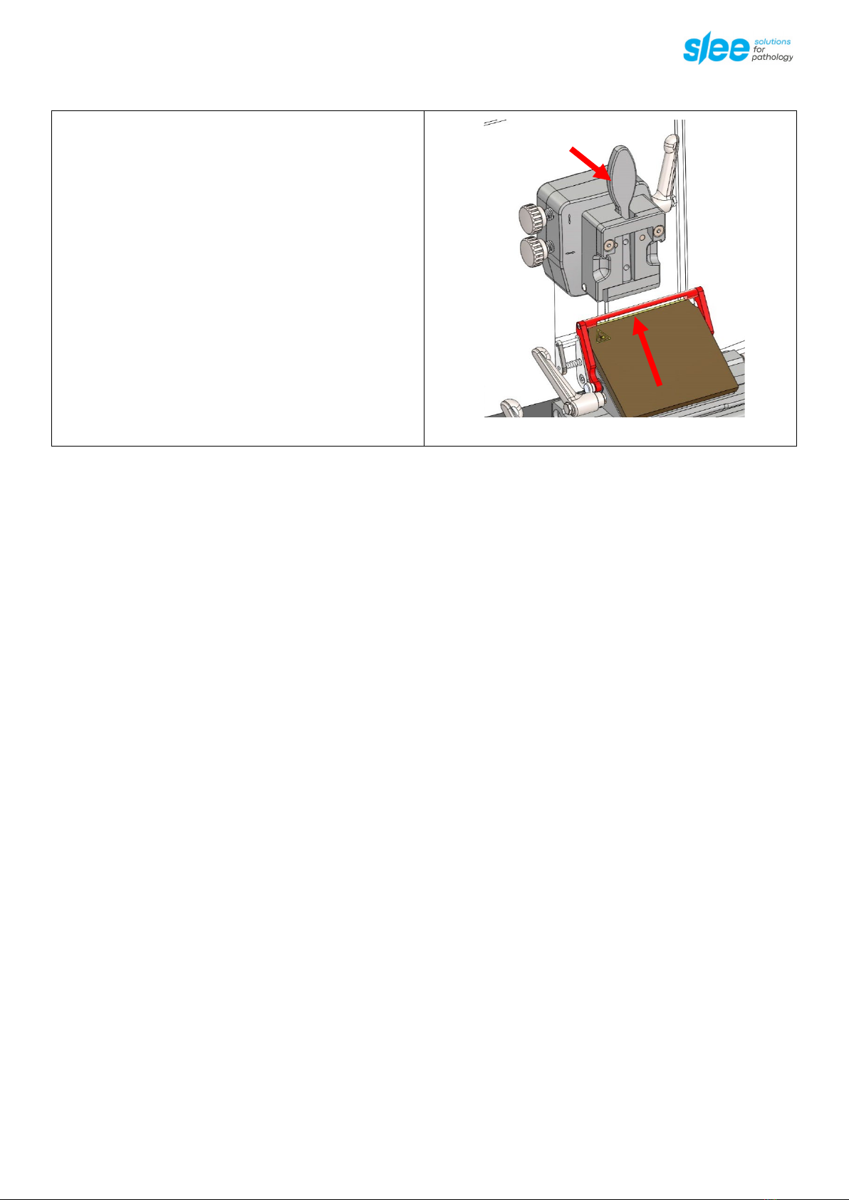
7.3 SPECIMEN ORIENTATION ADJUSTMENT
Turn hand wheel to its highest position and activate the
hand wheel stop (see chapter 3.1).
For orientation of the specimen, open the fixing lever on
the right side of the orientation.
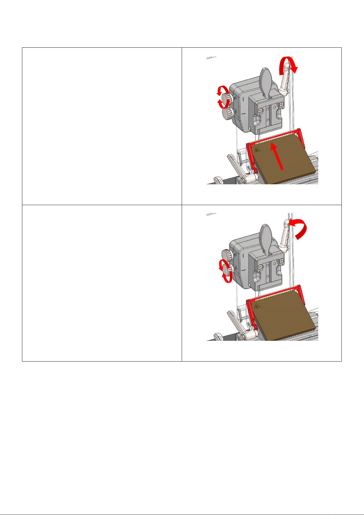
For upward and downward orientation use the upper ori-
entation wheel (see fig.).
For orientation to the left and right use the left orientation
wheel (see fig.).
Opening of orientation fixation lever and orientation of
specimen holder upwards and downwards
For orientation in the z-axis, turn the cassette clamp (see
fig.).
Fix the specimen orientation by locking the clamping lever
on the right side of the specimen holder.
Loosen the finger guard and the handwheel lock (see chap-
ter 3.1) for cutting the specimen.
Change specimen orientation to right or left and sample
orientation in z-axis
Table of contents
Other Slee Medical Equipment manuals


Popular Medical Equipment manuals by other brands


Getinge
Getinge Arjohuntleigh Nimbus 3 Professional Instructions for use

Mettler Electronics
Mettler Electronics Sonicator 730 Maintenance manual

Pressalit Care
Pressalit Care R1100 Mounting instruction

Denas MS
Denas MS DENAS-T operating manual

bort medical
bort medical ActiveColor quick guide

AccuVein
AccuVein AV400 user manual


