sleep8 450 User manual

450
OWNER’S MANUAL
Actual product appearance and functionality may vary from photographs, illustrations and descriptions included in this manual.

Safety Precautions and Usage Statements 1-4.......................................................................
Parts List .......................................................................................................... 5
......................................................................................Base and Remote Overview 6
...........................................................................................Quick Reference Guide 7
................................................................................................Installation Guide 8-9
...................................................................................................Remote Control 10
..................................................................................................Power Down Box 12
............................................................................................Remote Control Pairing 11
...................................................................................................Troubleshooting 17
........................................................................................................Deutsch 18-24
......................................................................................................Português 25-32
........................................................................................................Español 33-39
...........................................................................................................Notes 40-41
...............................................................Headboard Bracket Installation Guide (Optional) 15-16
.......................................................................................Connecting Strap (Optional) 14
.....................................................................................Syncing Two Bases (Optional) 13
Table of Contents

TO REDUCE THE RISK OF SHOCK, BURNS, FIRE OR INJURY:
For optimal safety and operation, plug bed base into a surge protector
(not included). The bed base should only be plugged directly into a
wall outlet or surge protector (strongly recommended). Always unplug
the base from the electrical outlet before servicing any part of the base.
To reduce risk of electric shock, unplug the base before cleaning. To
safely disconnect, ensure the base is in a flat position with all motors
heated surfaces. Never operate the base when the air openings are
blocked. Keep air openings free of lint, hair and the like. Do not drop
or insert any object into any opening. Discontinue use of the bed base
and contact a qualified service center if: it has a damaged cord or plug,
if it is not working properly, or it has been dropped into water. Only
use this bed base for its intended use as described in this manual. Do
not use accessories/attachments that are not recommended by the
manufacturer. Close supervision is required when the bed base is used
by or near children, convalescents, disabled persons or pets. Improper
connection of the equipment can result in the risk of electrical shock,
electrical fire or faulty operation of this bed bas . If the plug does not
fit your outlet, contact a qualified electrician to install a suitable outlet
Unauthorized modification or failure to use a wall outlet or surge
protector could void the electrical portion of your warranty.
PETS AND CHILDREN:
Immediately dispose of all packing materials as it may pose a smothering
risk to small children and pets. To avoid injury, it is not advised to allow
children and small pets to play on or under the bed. Children should not
Attention: Important Safety Disclaimers
Read all instructions before using your adjustable base. Save these instructions.
operate the bed base without adult supervision.
PACEMAKERS:
Some products contain Neodymium MAGNETS which may interfere
with devices such as pacemakers, ICD’s and any other device sensitive
to magnetic fields. It is STRONGLY recommended that owners of
such medical devices consult their physician prior to using products
that contain Neodymium MAGNETS. It is also possible that some
pacemakers may falsely interpret the optional massage feature
vibrations as movement/exercise. This is a common occurrence with
pacemaker. Please consult your physician before using the massage
feature.
IN-HOME USE AND HOSPITAL STANDARDS:
Ergomotion adjustable bed bases are designed solely for in-home use.
This base was not designed as a hospital bed and is not designed to
meet hospital standards. Do not use this base with TENT TYPE oxygen
therapy equipment or near explosive gases.
ADDITIONAL SAFETY FEATURES
Casters (optional leg accessory) are equipped with locking wheels to
prevent unwanted movement. Even when locked and unable to roll, it
is possible for the casters to slide. Free release head and foot motors
are designed to lower the mattress by retracting only with gravity, never
pulling downwards, which minimizes pinch points.
1
Safety Precautions and Usage Statements
LIFTING/LOWERING MECHANISMS
The lift/lower feature will emit a minimal humming sound during
operation. This is normal. During operation, the lift arm wheels make
contact with the platform support of the base. This contact may result in
metal on metal or metal on plastic contact. This applies slight tension on
the moving components and resonance is reduced to a minimum level.
If excessive noise or vibration is experienced, reverse the movement
action (up or down) of the base with the remote control. This should
realign the base’s activating mechanisms to the proper operational
position. In normal base operation, the wheels, which allow the bed
to maintain its distance from the wall, will make contact with the steel
platform supports of the base creating a contact noise. When entering,
exiting or shifting weight on the base, this contact noise may be audible
as the wheels make contact. This is normal.
MATERIALS
Ergomotion adjustable bases are constructed from various materials
including woods, metals, plastics and fabrics. Tension, pressure or
movement applied to the frame, platform or shroud through general use
may create an audible sound.
MASSAGE OPERATION AND LOCATION ENVIRONMENT
The massage feature will emit a tone during operation. This is normal.
As the massage intensity level is increased, the tone will intensify.
The volume of this tone is directly related to the location environment.
For example, when demonstrated in a show room, the surrounding
environmental noise will cover some of the massage noise. However,
when installed in a home setting with wooden floors, carpeted or not, the
massage volume will be more noticeable. To minimize this resonance,
place a piece of carpet, or rubber caster cups, under each leg or caster
of the base. It is possible to experience vibration or noise from the
exterior bed frame, headboard brackets, headboards or footboards if
mounting bolts are not firmly tightened
Levels 1-6 of massage intensity represent the revolutions of the motor
per minute. Level 6 provides the maximum number of RPMs. However,
this does not mean that the feeling of vibration is the strongest.
Depending on the mattress material, thickness, and positioning of the
the massage intensity setting that suits them best. It is important to
understand the physics of vibrations. Just as an engine may run rough
during idle, as the RPMs increase, the vibrations change concurrently.
TOLERANCE
All Ergomotion adjustable foundations, depending on make and
model, are designed and manufactured to perform and function within
designated quality control parameters. Bases are subject to meticulous
and rigorous inspections during the quality control process to ensure
bases will operate within these standards during normal operating use.
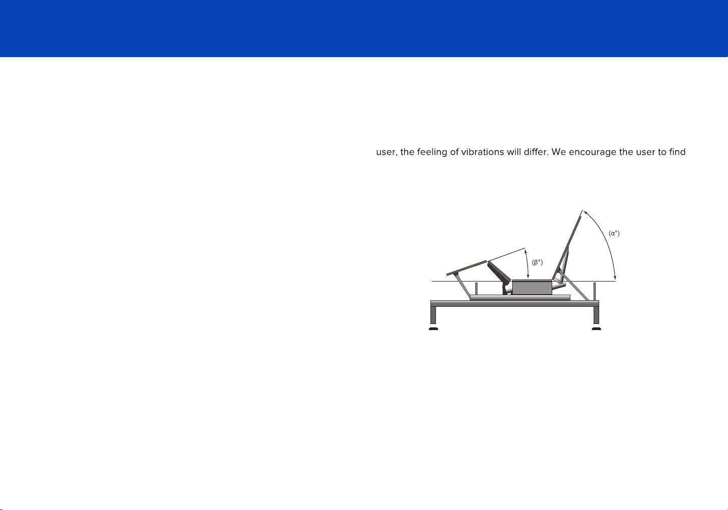
Normal operating use is defined as the following: Adjustable foundation
is to be operated with a mattress and load. Testing procedures require
lifetime cycle tests with up to 120kg distributed load. The angle
(designated “ α” in figure 1) between the back section and the flat section
2
Safety Precautions and Usage Statements

3
for various configurations of the mattress support platform shall be ± 3°,
which translates to a tolerance of up to 1 ½”.
The angle (designated “β” in figure 1) between the flat section and foot
section for various configurations of the mattress support platform shall
be ± 3°, which translates to a tolerance of up to ¾”.
Any adjustable foundation deemed to be within these allocated
tolerances is considered to have met the manufacturer’s quality control
standards.
THAT “NEW PRODUCT” SMELL:
Some people notice a slight odor to their new adjustable base—this
can come from our material manufacturing process. This smell is normal
and usually disappears before the product reaches you. Sometimes,
however, this smell may still be noticeable. It usually disappears after
a few weeks, providing adequate ventilation of the product and the
environment.
BREAK IN PERIOD:
You can speed up the break-in period by simply spending time in the
adjustable bed through activities such as reading, watching TV or
playing with the kids or grandkids. The extra movement will help the
adjustable base respond to weight and temperature changes. Some
of the materials in our adjustable bases such as the woods, metals
and plastics used in the platform, frame and components are sensitive
to moisture content and temperature and may make sounds in colder
environments.
PAIRED OPERATION:
When operating a “paired” split base setup there may be a time latency
up to 1.5 seconds between each bases articulation.
WEAR AND TEAR:
Wear and tear is damage that naturally and inevitably occurs as a result
of normal use or aging.
FABRIC CARE:
To prolong the life of your fabric, protect from direct sunlight whenever
possible. For spot cleaning, wipe area with a light damp sponge or
vacuum with a soft brush attachment to remove particles. Keep at a
minimum of 30cm (12 inches) away from direct heat sources. For a
deeper cleaning, blot liquid spills with a clean dry cloth. Wipe with a
clean cloth dampened with warm water. Do not wet excessively. A soft
bristle brush may be used to remove ingrained soil. Avoid scratching by
gentle brushing. Wipe with a clean cloth dampened with warm water to
remove residues. Dry in shade away from direct heat. If persistent marks
remain visible after cleaning, seek professional advice.
PRODUCT RATINGS:
The lift motors are not designed to operate continuously for more than
[2] minutes in an [18] minute time period or approximately 10% duty
cycle. Attempting to circumvent or exceed this rating will shorten the
life expectancy of the product and may void the warranty. The massage
motors are not designed to operate continuously for more than 30
minutes at a time. Please allow the massaging system to rest for 30
minutes after automatic massage shut o before restarting.
WEIGHT LIMITS:
This product is not rated to support weights in excess of 750 pounds
/340 kg inclusive of the mattress and bedding. The base will structurally
support this weight, provided it is evenly distributed across the bed base.
The adjustable base is not designed to support or lift this amount in the
head or foot sections alone. Exceeding this weight restriction could
damage the bed and/or cause injury and will void the warranty.
Safety Precautions and Usage Statements

4
IMPORTANT DO’S AND DON’TS
DO:
• Plug your adjustable base into a power surge protector.
• Evenly distribute weight when sleeping in a split setup. Uneven
distribution of weight can cause the base to raise unevenly.
• Call Customer Service for any technical issues. Do not try to force
the base down, this can damage the motors or frame.
• Use mild soap and water to clean your adjustable base if staining
occurs.
• Keep in mind that adjustable bases are recommended to be used
with adjustable friendly mattresses.
• Lower to the flat (horizontal) position after use and in between
presets.
• Register your warranty as soon as your adjustable base has been
delivered.
DON’T:
• Sit on corners/edges of base, this may warp the frame, struts or
foam.
• Tilt the base on its side. This can damage the legs and/or leg
screws.
• Stand or jump on the adjustable base at any time, this can damage
the frame and motors.
• Drag the base to move it. Dragging the base could damage the
frame, strip the nut/bolts or break the legs. Purchase castors if you
plan on moving your base routinely.
• Enter and exit the adjustable base with the head and/or foot in
the articulated position. Enter or exit your adjustable in the fla
(horizontal) position.
• Tinker with or modify base. This will void the warranty.
• Press down on the head or foot while actuated can damage frame
and motors. SAVE THESE INSTRUCTIONS.
Safety Precautions and Usage Statements
FCC Compliance:
NOTE:This equipment hasbeen tested and found to comply with
thelimits for a Class B digitaldevice, pursuant to part 15 of the FCC
Rules. These limitsare designed to provide reasonable protection
against harmful interference in a residentialinstallation. This equipment
generates, uses and can radiate radio frequency energy and, if not
installedand used in accordance with the instructions, may cause
harmful interference to radio communications. However, there is no
guarantee that interference will not occur in a particular installation. If
this equipment doescauseharmful interference to radio or television
on, the user isencouraged to try to correct the interference by one or
reception, which can be determined by turning the equipment o and
more of the following measures:
• Reorient or relocate the receiving antenna.
• Increase the separation between theequipment and receiver.
•
to which the receiver is connected.
Connect the equipment into an outlet on a circuit dierent from that
• Consult the dealer or an experienced radio/TV technician for help.

5
All electronics and components that need to be installed are
located in boxes under the base or attached to the frame.
A) Wireless Remote Control and AAA Batteries (3)
B) Mattress Retainer Bar*
C) Legs (4)
D) Power Cord
E) Power Supply
F) Power Down Box
(9 volt batteries not included)
G) Connecting Strap‡*
H) Sync Cord‡
Misc Parts (not included):
I) Surge Protector
J) 9 Volt Batteries (2)
‡ Only included in the width of the bases ≤ 1000mm.
Before discarding the packing materials, ensure all the parts are accounted for.
A)A) B)*C)
D) E)
G)‡*H)‡
I) J)
F)
MISC Parts (NOT INCLUDED)
Parts List
These items are attached to the base for shipping
purposes. Carefully remove from base and set aside.
*

6
Control Box
Power Down Box
Head Motor
Massage MotorMassage Motor
Massage MotorMassage Motor
Base and Remote Overview
10, 20, 30 Minute
Massage Timer Lights
TV Preset Position
Lifts and Lowers Head
Zero G® Preset Position
FLAT Preset Position
Lifts and Lowers Foot
Relax Preset Position
Turn on Head and
Foot Massage
Turn on Head and Foot
Massage Timer
Head Massage On/O
(6 Intensity) Foot Massage On/O
(6 Intensity)
Foot Motor

7
Not to scale. For illustration purposes only. Read all instructions before beginning installation.
If installing a split unit, see page 13.
Head Vibration
Foot Vibration
Massage Motor
Splitter Cable
Quick Reference Guide
Power Cord
Foot
Motor
Head
Motor
Power Supply
Input Cord
Power Down Box
Control Box

8
STEP 4
STEP 5
STEP 6
Uncoil input Power Cord (connected to
Control Box’s power port) and plug into
Power Supply.
Locate the Power Down Box and install (2) 9 Volt batteries
(not included).
Uncoil the Power Cord and connect to the
Power Supply. Place Power Supply on the
ground and extend from the base. Ensure
that the Power Supply and all attached
cords are directed toward the desired surge
protector.
To sync two bases see detailed installation
instructions on page 13.
Always use two people when setting up the base.
STEP 1
STEP 2
STEP 3
Place the bed base box in a desired location with the top of
the box facing up.
Remove the binding straps and packing materials, making
sure not to puncture the box with any sharp objects.
Remove the bed base from the box keeping the bottom of the
base facing upwards.
To install the legs, thread the
washer over the bolt of the leg
with the recessed side facing the
leg, and tighten by hand.
Do not over tighten.
To install Headboard Brackets (sold separately)
see instructions on page 15.
Installation Guide

9
Installation Guide
STEP 7
STEP 8
STEP 9
Carefully flip the base over on to its legs. Important: Two people
are required to move the bed base. Do not drag across the floor.
Do not rest frame on its side, excessive pressure may damage
the legs.
A surge protector is recommended.
Quickly test remote functions to verify proper setup
before placing mattress on base. Return the base to a flat
position before placing the mattress on top.
STEP 10
Slide the left side of the mattress retainer bar into the bracket.
Pull the retainer bar to the opposite bracket and secure the
right side.
Setup is now complete! Test all functions on remote.
Plug the power cord into a power source.

10
Remote Control
Remote Control arrives paired to the adjustable base.
Three (3) AAA batteries are required to operate the
remote.
MASSAGE FEATURE
ADJUST
ONE TOUCH BUTTONS
The HEAD ▲ ▼ arrows lift and lower
the head section of the base.
The FOOT ▲ ▼ arrows lift and lower
the foot section of the base.
The MASSAGE button activates head and foot massage at levels 1, 3, 6 and
then turns head and foot massage o.
The light on the top of theremote indicates a 10, 20or 30 minute timer
setting.Massage will automaticallyshut o after 10 minutes ifthe massage
timer isn’t set.
The HEAD button will turn on the head massage. Cycle through 6 massage
intensities.
The FOOT button will turn on the foot massage. Cycle through 6 massage
intensities.
The TIMER/ALL OFFbutton Starts massage at level 3. Select a 10, 20 or 30 minute
massage interval. Pressing a fourth time will turn o massage.
One touchZERO G preset position.
Zero-G adjusts your legs to a higher
level than your heart helping to
and promote circulation.
relieve pressure o the lower back
One touchFLAT preset position.
One touchTV preset position.
One touchRELAX preset position.

Remote Control Pairing
Remote Pairing
*ALTERNATE REMOTE PAIRING PROCESS!
Locate the Control Box (see base overview and quick
reference guide for corresponding base) and press the Reset/
Pairing button twice. A pairing LED light will illuminate green
on the Control Box. On the back of the remote, press and
hold the PAIR button. The PAIR button will illuminate blue and
start fashing. When the PAIR button stops fashing, the green
LED light on the Control Box will go out. Release the PAIR
button. The remote is now paired to the adjustable base.
Power Down
Button
Test all remote functions. If the remote buttons do not impact
the adjustable base movements, please repeat the process
again.
STEP 1
The original remote that comes in the box is already paired to the adjustable base. No further action is required. In the event that the
remote is not paired with the base, follow the steps below.
Locate the Power Down Box and
press the button TWICE. A light
on the Power Down Box will
illuminate.
STEP 3
PAIR
Button
STEP 2
Pairing
LED Light
Reset/Pairing
Button
11
flashing. When the PAIR button
stops flashing, the illuminated
Remove the back cover of the
remote, press and hold down
the PAIR button. The PAIR button
will illuminate blue and start
light on the Power Down Box will
go out. Release the PAIR button.
The remote is now paired to the
adjustable base.

Store the Power Down Box in a convenient location for emergency use.
Two (2) 9 Volt batteries are required to operate the power down feature and are NOT included.
For emergency use only, in case of a power outage.
In the event that the base is stuck in an articulated position during a power outage,
the Power Down Box will return the base to a FLAT position. Batteries are not to be
used for normal operation of the base.
Install the 9 Volt batteries into the provided Power Down
Box.
Do not mix brand name batteries.
Press the button on the
Power Down Box to lower
the base to FLAT position.
OVERVIEW
STEP 2STEP 1
Control Box
Power Down
Box
Power Down Box
12

13
If bases become mismatched, pressing the FLAT button will
re-sync the mechanical positions.
PERFORMANCE NOTES
Syncing Two Bases (Optional)
A Sync Cord is included with the base. Not available on Queen, Full or Full-Long size bases.
The Sync Cord connects the two control boxes to a single remote for the synchronization of two bases.
Disconnect the Power Down Box cable from each Control Box
or splitter cable. Make note where the cable was plugged in.
Connect the male end of each Sync Cord to Control Box or
splitter cable. Insert it into the same port that you disconnected
the Power Down Box from in Step 2.
Unplug bases from power source.
Connect each Power Down Box male connection to the sync
cord female connection (refer to illustration at right).
STEP 3
STEP 2
STEP 1
STEP 4
STEP 5
Plug bases back into the power source.
STEP 6
Check to ensure all cords are securely attached. Both remotes
will now operate both bases simultaneously.
The system is now linked. Pressed buttons on either remote
will control the two bases simultaneously.
Power Down
Box 1
Sync Cord
Power Down
Box 2
Control Box 1 Control Box 2

Connecting Strap (Optional)
If any split setup is being installed, plastic connecting straps are provided (one per base) to secure the bases
together. Use both straps to secure the head and foot portions together.
STEP 2
STEP 3
STEP 1
With the bases in their desired location, slightly loosen both
legs to allow the strap to fit on the leg bolt, between the leg
washer and frame.
Slide side (a) of the connecting strap onto leg bolt.
Swing the strap and connect side (b) to the leg bolt.
Secure the strap by shifting to the left.
Re-tighten legs. Do not over tighten. Use the remaining strap
on other end of the base.
14
ab

Headboard Bracket Installation Guide (Optional)
15
Attach the mounting plate to the headboard bracket vertically as
shown using 4 short bolts and 4 nuts.
Headboard Brackets are an optional accessory and are not included.
A 9/16” & 1/2” socket and crescent wrench are necessary to complete installation.
HEADBOARD BRACKET COMPONENTS
Headboard Bracket (2) Mounting Plate (2) Long Bolt (8) Short Bolt (10) Nut (18)
STEP 1

16
Headboard Bracket Installation Guide (Optional)
STEP 2 STEP 3
A.
B.
A. B.
Flip base upside down to access the underside of the frame.
Lay the headboard bracket flush to the frame. Remove legs on
head end of bed if necessary. Line the rear large tab (B.) up
with the leg inserts on the frame. Line the smaller front tab (A.)
up with hole in the base frame. Screw leg into frame; hand
tight only.
Position base so the headboard brackets line up with the
mounting holes on headboard. Make sure bracket is flush with
the mounting plate and secure with 4 long bolts. Repeat this
step on other side of base.

17
Troubleshooting
• Check under the bed base to verify that the wired connections are secure and that there are no cords or bedding
obstructing the movement of the base.
• Check to ensure the green LED light is illuminated on the control box. If there is no light, verify that the input and
power cords are properly connected.
• Unplug the base for 1 hour to reset the electronic components.
electrical surge protector is recommended).
• Remove and replace full batteries in the remote control and re-pair the remote to the base (see page 11).
If issue is not resolved by following the instructions above, locate serial number on warranty card or back of remote and call
Customer Service Center: 8-800-200-40-90
If one or more functions on the bed base have stopped operating:

Deutsch
spielen. Kinder sollten das Bettgestell nicht ohne Aufsicht Erwachsener
bedienen.
HERZSCHRITTMACHER :
Einige Produkte enthalten Neodym-MAGNETEN, die Geräte wie Herzschritt-
macher, ICDs und andere magnetfeldempfindliche Geräte stören können. Es
wird DRINGEND empfohlen, dass Besitzer solcher medizinischen Geräte ihren
Arzt konsultieren, bevor sie Produkte verwenden, die Neodym-MAGNETEN
enthalten. Esist auch möglich, dass einige Schrittmacher die Vibrationsbewe-
gungen der optionalen Massagefunktion fälschlicherweise alsBewe-
gung/Übunginterpretieren. Dies tritt häufig bei Produkten auf, die eine
vibrierende Bewegung verursachen und wirddasFunktionieren des
Herzschrittmachers wahrscheinlich nicht beeinträchtigen. Bitte konsultieren Sie
Ihren Arzt, bevor Sie die Massagefunktion nutzen.
REGELN FÜR DIENUTZUNG ZUHAUSEUND IMKRANKENHAUS :
Die verstellbaren Bettgestelle von Ergomotion sind ausschließlich für den
Heimgebrauch bestimmt. Dieses Bettgestell wurde nicht als Krankenhausbett
konzipiert undentspricht nicht den Krankenhausstandards. Verwenden Sie
oder in der Nähe von explosiven Gasen.
ZUSÄTZLICHESICHERHEITSVORRICHTUNGEN
Die Rollen (optionales Beinzubehör) sindmit Feststellrädern ausgestattet, um
ungewollte Bewegungen zu verhindern. Doch selbst wenn sie blockiert sind
undnicht rollen können,können die Rollen gleiten. Kopf- und Fußmotoren mit
Freiauslösung sind so konstruiert,dass sie die Matratze senken,indem sie nur
mit der Schwerkraft zurückgezogen werden und niemalsnach unten ziehen,
wodurch die Klemmpunkte minimiert werden.
HEBE - UND SENKMECHANISMEN
Die Hebe- / Senkfunktion erzeugt während des Betriebs ein minimales
Brummen. Das ist normal. Während des Betriebs berühren die Hubarmräder
den Plattformträger des Bettgestells. Das kann zueinem Kontakt zwischen
beweglichen Komponenten einer Spannung ausgesetzt und die Resonanz
wird auf ein Minimum reduziert. Wenn übermäßige Geräusche oder Vibra-
tionen auftreten,führen Sie den Bewegungsvorgang (heben oder senken) mit
der Fernbedienung aus. Diessollte die Aktivierungsmechanismen des Gestells
auf die richtige Betriebsposition ausrichten. Bei normalem Betrieb treten die
18
pg.1-4 Sicherheitsvorkehrungen und Nutzungshinweise
Achtung: Haftungsausschluss
LesenSiealle Anweisungen, bevor Sie Ihr verstellbares Bettgestell benut-
zen. BewahrenSiedieseAnleitung sorgfältig auf.
UM DAS RISIKOVON SCHOCK, VERBRENNUNGEN, BRAND ODER
VERLETZUNGEN ZU REDUZIEREN :
Für optimale Sicherheit und Betriebschließen Sie das Bettgestell an einen
Überspannungsschutz an (nicht im Lieferumfang enthalten). Das Bettgestell
sollte nur direkt an eine Steckdose oder einen Überspannungsschutz anges-
chlossen werden (wird dringendempfohlen). Ziehen Sie immer den Netzsteck-
er aus der Steckdose, bevor Sie Teile des Bettgestells warten. Um das Risiko
eines Stromschlags zu verringern, ziehen Sie den Netzstecker heraus, bevor
Sie mit dem Reinigen beginnen. Um die Verbindung sicher zutrennen, stellen
Sie sicher, dass sich das Bettgestell bei ausgeschaltetemMotor in einer
flachen Position befindet, undziehen Sie erst dann den Stecker aus der
Steckdose. Halten Sie das Netzkabel von heißen Oberflächen fern. Betreiben
das Bettgestell vorerst nicht weiter benutzen sich an ein qualifiziertes Kunden-
dienstzentrum wenden: wenn ein Kabel oder Stecker beschädigt ist, nicht
richtig funktioniert oder insWasser gefallen ist. Verwenden Sie das Bettgestell
nur für den gemäß dieser Anleitungvorgesehenen Gebrauch. Verwenden Sie
keine Zubehörteile, die nicht vomHersteller empfohlen werden. Eine enge
Überwachungist erforderlich, wenn das Bettgestell von oder in der Nähe von
Kindern, Rekonvaleszenten,Behinderten oder Haustieren benutzt wird. Bei
unsachgemäßer Verbindung des Geräts besteht die Gefahr eines elektrischen
Schlags, elektrischen Feuersoder eines fehlerhaften Betriebs. Wenn der
Stecker nicht in Ihre Steckdose passt, wenden Sie sich an einen qualifizierten
Elektriker, um eine geeignete Steckdose zu installieren. Nicht autorisierte
Änderungen oder die Nichtbenutzungeiner Steckdose oder eines Überspan-
nungsschutzeskönnen den elektrischen Teil Ihrer Garantie ungültig machen.
HAUSTIERE UND KINDER :
Entsorgen Sie sofort alle Verpackungsmaterialien, da diese für Kleinkinder und
Haustiere ein Erstickungsrisiko darstellen können. UmVerletzungen zu
vermeiden,sollten Kinder und kleine Haustiere nicht auf oder unter dem Bett
Other manuals for 450
1
Table of contents
Other sleep8 Massager manuals

sleep8
sleep8 POWER EYES User manual

sleep8
sleep8 POWER NECK User manual

sleep8
sleep8 Smart Jet S User manual

sleep8
sleep8 633 User manual

sleep8
sleep8 POWER BACK User manual

sleep8
sleep8 Stress Free User manual

sleep8
sleep8 POWER MOOD User manual

sleep8
sleep8 Smart Jet User manual

sleep8
sleep8 SMART ANTI-SNORE User manual


