PRIOR TO INSTALLATION
Prior to installing the Sloan OPTIMA equipped Flushometer, install the items
listed below as illustrated in Figures 1 through 3.
•2-gang electrical box — 4" x 4" x 2-1/2" (102 mm x 102 mm x 64 mm) for
sensor; see paragraph entitled “Sensor Location”
•2-gang electrical box — 4" x 4" x 2-1/2" (102 mm x 102 mm x 64 mm) for
transformer (mount in a convenient location)
•2-gang electrical box — 4" x 4" x 2-1/2" (102 mm x 102 mm x 64 mm) for
solenoid operator, see paragraph entitled “Solenoid Operator Location”
(Models 110/111 ES-S,115 ES-S & 116 ES-S)
•Electrical wiring to the transformer box (120 VAC, 2 amp service requiredfor
each EL-154, 24 VAC, 50 VA transformer used)
•Closet fixture
•Drain line
•Water supply line
Important:
•ALLELECTRICALWIRINGISTO BEINSTALLEDINACCORDANCE WITH
NATIONAL/LOCAL CODES AND REGULATIONS.
•ALL PLUMBING IS TO BE INSTALLED IN ACCORDANCE WITH
APPLICABLE CODES AND REGULATIONS.
•WATER SUPPLY LINES MUST BE SIZED TO PROVIDE AN ADEQUATE
VOLUME OF WATER FOR EACH FIXTURE.
•A 24 VACSTEP-DOWN TRANSFORMER MUST BEUSED.
•USE APPROPRIATE PRECAUTIONS WHILE CONNECTING
TRANSFORMER TO 120 VAC POWER SOURCE.
•FLUSH ALL WATER LINES PRIOR TO MAKING CONNECTIONS.
The Sloan ROYAL®is designed to operate with 15 to 100 psi (104 to 689 kPa)
of water pressure. THE MINIMUM PRESSUREREQUIRED TO THEVALVE IS
DETERMINED BY THE TYPE OF FIXTURE SELECTED. Consult fixture
manufacturer for pressure requirements.
Most Low Consumption water closets (1.6 gallon/6 liter) require a minimum
flowing pressure of 25 psi (172kPa).
Protect the Chrome or Special finish of this Flushometer — DO NOT USE
TOOTHED TOOLS TO INSTALL OR SERVICE THE VALVE. Also, see “Care
and Cleaning” section of this manual.
IMPORTANT: WITH THE EXCEPTION OF CONTROL STOP INLET, DO NOT
USE PIPE SEALANT OR PLUMBING GREASE ON ANY VALVE
COMPONENT OR COUPLING!
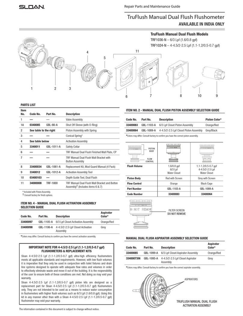
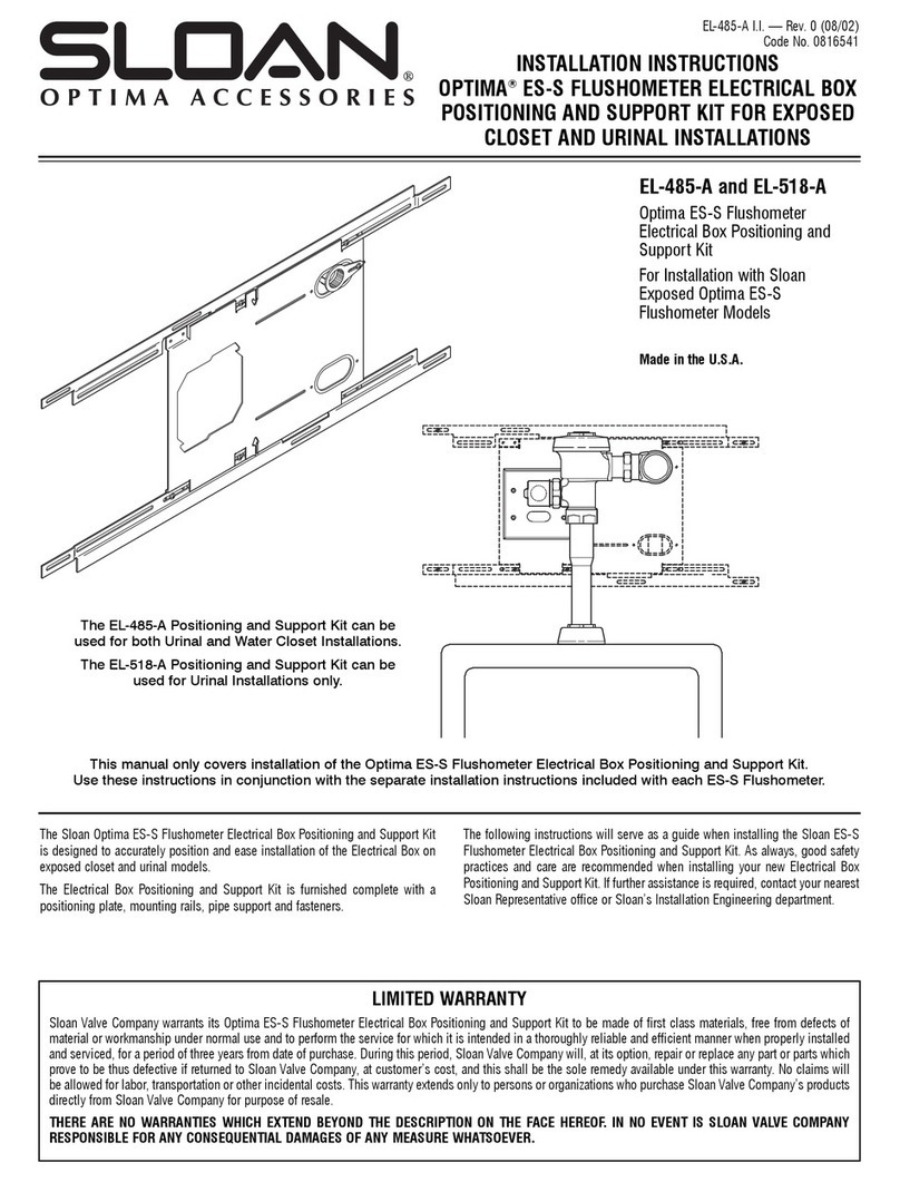
SENSOR LOCATION (Figures 1 and 2)
SENSOR LOCATION IS CRITICAL — Failure to properly position the
electricalboxestotheplumbingrough-inwillresultinimproperinstallation
and impair product performance. All tradesmen (plumbers, electricians,
tile setters, etc.) involved with the installation of this sensor operated
flushometer must be familiar with the requirements of its installation.
Improper installation may nullify the manufacturer’s warranty.
Note: A template is packaged with Model 110/111 ES-Svalves to
properly position electrical boxes.
MODELS 110/111 ES-S, 140 ES-S, 153 ES-S & 152 ES-S
Locate the 2-gang electrical box on the centerline of the Flushometer and 19"
(483 mm) abovethe topof thecloset fixture asshown inFigure 1.Use Appleton
#4SD1 Electrical Box and Appleton #8470 Plaster Ring or equivalent.
MODELS 115 ES-S & 116ES-S
Locate the right edge of the 2-gang electrical box on the centerline of the
Flushometer and 15" (381 mm) for Model 115 ES-S or 17" (432 mm) for Model
116ES-S abovethe topof theclosetfixtureas shownin Figure1.UseAppleton
#4SD1 Electrical Box and Appleton #8470 Plaster Ring or equivalent.
ALL MODELS
Note: Installplaster ring so screw holes are on left and right side of box.
Note: Break tiles to allow screw holes in plaster ring to show.
SOLENOID OPERATOR LOCATION (Figure 1)
MODELS 110/111 ES-S,115 ES-S & 116 ES-S
Electricalboxlocationiscritical.Locatethecenterlineofthe2-gangelectrical
boxbymeasuring2-3/4"(70mm)totheLEFTofthecenterlineoftheFlushometer
and 1-1/2" (38 mm) BELOW the centerline of the water supply. Use Appleton
#4SD1 Electrical Box and Appleton #8470 Plaster Ring or equivalent.
Note: Installplaster ring so screw holes are on left and right side of box.
Note: Break tiles to allow screw holes in plaster ring to show.
TOOLS REQUIRED FOR INSTALLATION
•Slotted screwdriver
•5/64" hex wrench (supplied)
•Sloan A-50 “Super-Wrench™” or smooth jawed spud wrench
•Wire stripper/crimping tool
INSTALLATION
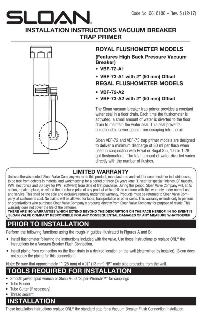
Step 1 — Install Transformer (Figure 3)
Install Transformer (EL-154) on a 2-Gang Electrical Box, 4" x 4" x 2-1/2" (102
mm x 102 mm x 64 mm) in a convenient location as shown in Figure 3.
Note: One Sloan EL-154 transformer can operate up to ten OPTIMA equipped
Flushometers. Run 18-gauge wire from transformer to Flushometer(s). Wire
supplied by others. DO NOT supply power to transformer until installation
of Flushometer is complete.
ELECTRICAL BOX
INSTALLATION
Figure 2
EL-1500-L SENSOR
NOTE: SENSORNOT
CONNECTED AND
INSTALLED UNTILSTEP 6
(VIEWWITH COVER REMOVED)
NOTE: INSTALL
PLASTER RING SO
THAT SCREW HOLES
ARE ON THE LEFT AND
RIGHT SIDE OF BOX
EL-141-A
OVERRIDEASSEMBLY
(INSTALL WITH OFFSET
PORTION IN DEVICE
COVER)
FINISHEDWALL
OPENING
TABS OF YOKE AND
SENSOR TO BE
MOUNTED ON TOP OF
FINISHED PLASTER OR
TILE WALL
4" (102 mm) SQ. x 2-1/8" (54 mm) DEEP
OUTLET BOX— APPLETON ELECT.#4SD1
OR EQUAL (BY CONTRACTOR)
4" (102 mm) SQ. BOX DEVICE COVER (PLASTER
RING) 3/4" (19mm) HIGH — APPLETONELECT.
#8470 OR EQUAL (BY CONTRACTOR)
FINISHED
TILE WALL
FINISHED
PLASTER WALL
EL-201
COVER PLATE
EL-1500-L CLOSET
SENSOR
“TO VALVE”
CONNECTION
“24 VAC IN”
CONNECTION
†MOUNT TRANSFORMER WITHIN 50
FEET (15 m) OF FLUSHOMETER
2-GANG ELECTRICALBOX —
4" x 4" x 2-1/2" (102mm x 102 mm x 64 mm)
EL-154
TRANSFORMER †
Figure 3 Note: A maximum often (10) Flushometerunits can operate from one (1)
Sloan EL-154 Transformer, Class2 UL Listed, 48 VA(min.) at 24 VAC,
plate mounted.


