manuals.online logo
Brands
  1. Home
  2. •
  3. Brands
  4. •
  5. Sloan
  6. •
  7. Plumbing Product
  8. •
  9. Sloan Optima EBF-550 Use and care manual

Sloan Optima EBF-550 Use and care manual

Repair Parts and Maintenance Guide
184
The information contained in this document is subject to change without notice.
Optima®EBF-85/EBF-187
Repair Parts and Maintenance Guide
1. Module emits audible “BEEPs” when activated.
A. Battery power is nearly exhausted. To ensure proper operation, insert
four (4) new C-size alkaline batteries. Check that the orientation
of each battery matches the positive (+) and negative (–) symbols
shown in the bottom of the battery compartment. Reattach battery
compartment to control module.
2. Sensor is activated but faucet DOES NOT deliver water.
INDICATOR: Module DOES NOT produce audible “BEEPs”.
A. Battery power is fully exhausted. To ensure proper operation, insert
four (4) new C-size alkaline batteries. Check that the orientation
of each battery matches the positive (+) and negative (–) symbols
shown in the bottom of the battery compartment. Reattach battery
compartment to control module.
B. Batteries are not installed properly. Check that the orientation of the
batteries match the positive (+) and negative (–) symbols shown in the
bottom of the battery compartment. Reattach the battery compartment
to the control module.
C. Solenoid valve module is not working properly. Replace EBF-11-A
solenoid valve module.
INDICATOR: Module produces audible “BEEPs” when batteries
are installed and after 30-second calibration procedure, but NOT
when a target is placed in the detection zone of the Sensor.
D. Fiber optic cable is not connected correctly to solenoid valve module
or was not connected when batteries were installed. Reconnect ber
optic cable to solenoid valve module. Open battery compartment to
reset electrical system. Check that the orientation of each battery
matches the positive (+) and negative (–) symbols shown in the bottom
of the battery compartment. Reattach the battery compartment to the
control module.
E. Fiber optic cable is not working properly. Replace EBF-1009-A sensor
cable, or EBF-10-A faucet/sensor assembly.
F. Solenoid valve module is not working properly. Replace EBF-11-A
solenoid valve module.
INDICATOR: Module produces audible “BEEPs” when a target is
placed in the detection zone of the sensor and solenoid valve
produces an audible “CLICK”, but NO water flows.
G. Water supply to faucet is not open. Open supply stop(s).
H. Bak-Chek®is installed backwards. Reinstall Bak-Chek(s).
I. Solenoid lter is clogged. Remove, clean, and reinsert. Replace with
EBF-1001-A or EBF-1004-A solenoid lter kit if necessary.
J. Aerator or spray head is clogged. Remove, clean, and reinsert.
INDICATOR: Module produces audible “BEEPs” when a target is
placed in the detection zone of the sensor, but solenoid valve
DOES NOT produce an audible “CLICK” and NO water flows.
K. Solenoid valve module is not working properly. Replace EBF-11-A
solenoid valve module.
3. Faucet delivers only a slow flow or dribble when sensor is
activated.
A. Water supply valve is partially closed. Open the supply stop(s)
completely.
B. Solenoid lter is clogged. Remove, clean, and reinsert. Replace with
EBF-1001-A or EBF-1004-A solenoid lter if necessary.
C. Aerator or spray head is clogged. Remove, clean, and reinsert.
4. Faucet DOES NOT stop delivering water or continues to drip after
user is no longer detected (automatic shut-off fails even when
batteries are removed).
A. Solenoid valve has been connected backwards. Disassemble solenoid
valve compression ttings at the inlet and outlet positions. Water
should ow from inlet through the solenoid valve to outlet according
to the direction shown by the arrow on the side of the solenoid valve.
Reconnect the ttings in the correct orientation.
B. Solenoid valve seat is dirty. Remove, clean, and reinsert solenoid lter.
Activate faucet several times to ush out dirt.
C. Solenoid valve is dirty. Backush by reversing water ow (opposite to
the direction shown by the arrow on the side of the solenoid valve)
through the solenoid valve. Reconnect the compression ttings in the
correct orientation. Activate faucet.
D. Solenoid valve module is not working properly. Replace EBF-11-A
solenoid valve module.
5. The water temperature is too hot or too cold on a faucet
connected to hot and cold supply lines with two Bak-Chek’s.
A. Supply stops are not adjusted properly. Adjust supply stops.
B. One Bak-Chek is installed backwards. Reinstall Bak-Chek.
NOTE: For some systems, a thermostatic mixing valve may be required.
TROUBLESHOOTING GUIDE
VALVE MODULE
SET SCREW
BATTERY
COMPARTMENT
COUPLING RING
ALIGN ARROWS
AND INSTALL
BATTERY
COMPARTMENT TO
VALVE MODULE
BATTERY
COMPARTMENT
BATTERY REPLACEMENT
Faucets and
Soap Dispensers
Repair Parts and Maintenance Guide
185 The information contained in this document is subject to change without notice.
Optima®EBF-550
Repair Parts and Maintenance Guide
New Base Gasket
The new base gasket
(in production since
October 1999) is shown
below. An older base
gasket design did not
have the u-shaped
drainage hole.
7
3
4A
4B
6
9
10A
10B
10E
11
13 12
8
3
19
EBF-650EBF-615
2
1
20
2
1
8A
10C
8C
8E
10D
5
5A
3
4A
4B
6
9
10A
10B
10E
11
13 12
8
3
19
EBF-650EBF-615
2
1
20
2
1
8A
10C
8C
8E
10D
5
5A
6
3
4A
4B
6
9
10A
10B
10E
11
13 12
8
3
19
EBF-650EBF-615
2
1
20
2
1
8A
10C
8C
8E
10D
5
5A
PARTS LIST—EBF-550 FAUCET
Item
No. Code No. Part No. Description
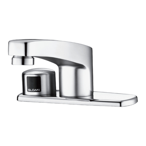
1A. 0315224PK EBF-222-A-ST Faucet and Sensor Assembly with Standard
Gooseneck Spout (EBF-550) w/ ETF-178 (new
sensor w/ phone jack
1B. 0315227PK EBF-222-A-SU Faucet and Sensor Assembly with Surgical Bend
Gooseneck Spout (EBF-550-S) w/ ETF-178 (new
sensor w/ phone jack
2. 0305784 ETF-178 Adapter for Spray Heads (not required for
AC-55-A Shower Spray Head)
3A. 0365147 ETF-621 2.2 gpm (8.3 Lpm) Laminar Flow Spray Head with
Key (female thread)
0365793 ETF-839 0.35 gpm (1.3 Lpm) Multi-Lam Spray Head
0305927 ETF-435 Replacement Key ONLY
3B. 0328134 AC-55-A Shower Spray Head Assembly, 2.2 gpm (8.3 Lpm)
4. 0315060 EBF-110-A Faucet Mounting Kit includes Base Gasket,
large Flat Washer, large Lockwasher, large
Nut, Mounting Spacer, Mounting Stud, small
Flat Washer, small Lockwasher, small Nut,
Anti-Rotation Screw, and Compression Fitting
Connector (male)
0365152 ETF-591 1/8” NPT Pipe to 3/8” Tube Male Compression
Fitting Connector
5. 0365758 ETF-740-A 6 VDC Solenoid Valve Assembly
5A. 0365774 ETF-742-A 6 VDC Solenoid Valve Only
6. 0365752 ETF-735-A Control Module
7. 3365461 ETF-617-A Bak-Chek®“T” Assembly
— 0365838 ETF-1003 36” Extension Cable (Optional)
—Not shown in illustration
For additional information about Sloan Mixing
Valves or Trim Plates, consult our Installation
Instructions and Maintenance Guides.
OLD MOUNTING KIT AND FAUCET SHANK
8. N/A†† EBF-110-A Old Faucet Mounting Kit included 3/8” Water
Supply Tube, Base Gasket, large Flat Washer,
large Lock Washer, large Nut, and Compression
Fitting Connector (order Items 4 and 10 as
replacement parts)
9. 0365058†† ETF-547 1/8” NPT Pipe to 3/8” Tube Female Compression
Fitting Connector
Note: earlier faucet models are not
compatible with the current models.
PARTS PRIOR TO SEPTEMBER 2009
11. 0315104 EBF-60-A Control Module Assembly
12. 0315254 EBF-1011-A Solenoid Replacement Kit
13. 3315029 EBF-113-A Single Solenoid Supply Compression Nut Kit
14. 3315018 EBF-79-A Mounting Hardware Kit
15. 3315222PK EBF-222A-ST Standard Gooseneck Spout & Old Style Sensor
OBSOLETE Assembly (Flat 7 wire Black Modular Plug)
16. 0315153 EBF-206-A Sensor Window w/ Cable Assembly
11
14
12
13
13
9
8
OLDER MOUNTING KIT
Faucets and
Soap Dispensers
372626_Master_Book_ccg.indd 183 9/18/17 7:55 AM
Repair Parts and Maintenance Guide
186
The information contained in this document is subject to change without notice.
Optima®EBF-550
Repair Parts and Maintenance Guide
1. Sensor LED does not function (sensor indicator light DOES NOT
flash during initial 10 minute set-up mode).
A. There is no visible indicator light. Normal operation. This is a normal
operating feature of the faucet.
2. Faucet DOES NOT deliver any water when Sensor is activated.
INDICATOR: Solenoid valve produces audible “CLICK.”
A. Water supply stop(s) closed. Open supply stop(s) completely.
INDICATOR: Solenoid valve DOES NOT produce an audible
“CLICK.”
B. Solenoid lead is not properly connected to the control module.
Disconnect and reconnect solenoid lead to the control module.
C. No battery or transformer (optional) power is being supplied to
sensor. Ensure that the batteries are installed properly. Check that
the orientation of each battery matches the positive (+) and negative
(—) symbols shown on the bottom of the battery compartment.
Reinsert the batteries into the control module. Transformer (optional) is
unplugged or wall receptacle has no power.
D. Sensor cable is not properly connected to the control module.
Disconnect and reconnect sensor cable to the control module.
E. Sensor range is set at minimum distance. Increase sensor range. Refer
to range adjustment in your installation instructions.
F. Control module assembly is not working properly. Replace control
module assembly.
3. Faucet delivers only a slow flow or dribble when sensor is
activated.
A. Water supply stop(s) partially closed. Open supply stop(s) completely.
B. Solenoid lter is clogged. Remove, clean and reinstall lter. Turn
off water supply at supply stop(s). Activate faucet to relieve system
pressure. Remove water supply line from inlet side of solenoid valve.
Remove cap, water line tting, gasket, lter housing and lter from
solenoid valve housing. Slide lter off lter housing. Clean lter
using fresh tap water only. If necessary, use a small brush to clean.
Use caution while cleaning to prevent damage to lter. If any lter
components are damaged, replace as necessary. Examine the gasket
for wear or damage; replace if necessary. Reinstall lter on lter
housing. Install lter housing, gasket, water line tting and cap onto
solenoid valve housing. Tighten cap securely. Reinstall water supply
line to inlet side of solenoid valve.
TROUBLESHOOTING GUIDE
OLD STYLE SENSOR INDICATOR LIGHTS NEW STYLE SENSOR INDICATOR LIGHT
C. Aerator is clogged. Remove, clean and reinstall aerator.
4. Faucet DOES NOT stop delivering water or continues to drip after
user is no longer detected (automatic shut-off fails even when
batteries are removed).
A. Solenoid valve has been connected backwards. Disconnect solenoid
valve compression ttings at both the inlet and outlet positions. The
water should ow from inlet through the solenoid valve to the outlet
according to the direction of the arrow shown on the side of the
solenoid valve. Reconnect the compression ttings in the correct
orientation.
B. Solenoid valve is dirty. Backush by reversing water ow (opposite to
the direction shown by the arrow on the side of the solenoid valve)
through the solenoid valve. Reconnect the compression ttings in the
correct orientation. Activate faucet.
C. Solenoid valve module is not working properly. Replace solenoid
valve module.
5. The water temperature is too hot or too cold on a faucet
connected to hot and cold supply lines with Bak-Chek®Tee.
A. Supply stops are not adjusted properly. Adjust supply stops.
NOTE: For some systems, a thermostatic mixing valve may be
required.
6. The RED LED turns on in the control module (below deck).
A. One (or more) of the batteries is “dead”. To ensure proper operation,
insert four (4) new AA-size Alkaline batteries. Check that the
orientation of each battery matches the positive (+) and negative (–)
symbols shown on the bottom of the battery compartment. Reinsert
batteries into the control module.
B: Upon start-up mode the control module circuitry also tests the
batteries and the RED LED turns on if the battery voltage is low, no
RED LED light indicates normal battery voltage.
C. If reset (initiates start up mode) button is
pressed, the battery voltage is checked.
If voltage is too low, product is stopped
from operating and RED LED will turn on.
No RED LED light indicates normal battery
voltage.
7. The GREEN LED initially turns on in the
control module (below deck) during
start up mode, then will not appear
again.
INDICATOR: For the 1st ten minutes of operation (batteries
inserted or reset button pressed) the GREEN LED will turn on
when there is a target present (hands in front of sensor). After
ten minutes, the GREEN LED will no longer turn on.
A. This is a normal operating feature of the faucet.
FOUR (4)
NEW AA-SIZE
ALKALINE
BATTERIES
INLET SIDE OF SOLENOID VALVE HOUSING
FILTER
FILTER HOUSING
WATER LINE FITTING
GASKET
CAP
SCREWS (2)
LOCKING
TABS
OPTIONAL
PLUG-IN
TRANSFORMER
RESET
BUTTON
LED
Faucets and
Soap Dispensers
Repair Parts and Maintenance Guide
187 The information contained in this document is subject to change without notice.
Repair Parts and Maintenance Guide
Optima®EBF-615/EBF-650
EBF-615 EBF-650
3
4A
4B
7
6
9
10A
10B
10E
11
13 12
8
3
EBF-650EBF-615
2
1
2
1
8A
10C
8C
8E
10D
PARTS LIST—EBF-615 AND EBF-650 FAUCETS
Item
No. Code No. Part No. Description
1. 0365400 ETF-749-A Sensor Only
2. 3365092 ETF-1023-A 0.5 gpm (1.9 Lpm) Spray Head with
Key (male thread)
3365093 ETF-1024-A 2.2 gpm (8.3 Lpm) Aerator Spray Head
with Key (male thread)
3365162 ETF-1029-A 2.2 gpm (8.3 Lpm) Laminar Flow (male thread)
3365756 ETF-1039-A 0.35 gpm (1.3 Lpm) Multi-Lam Spray Head VR
3. 0305927 ETF-435 Replacement Key Only for ETF-1023-A
0.5 gpm (1.9 Lpm) Spray Head and ETF-1024-A
2.2 gpm (8.3 Lpm) Aerator Spray Head
4A. 3365088 ETF-546-A Faucet Mounting Kit for EBF-650 includes Base
Gasket, two (2) Slotted Mounting Washers, two (2)
Wing Nuts and ETF-547 Compression Fitting
Connector
4B. 0315085 EBF-123-A Faucet Mounting Kit for EBF-615 includes Base
Gasket, Spacer, Washer, 9/16” Lockwasher,
1/4” NPSM Hex Nut and ETF-547 Compression
Fitting Connector
5. 0365058 ETF-547 1/8” NPT Pipe to 3/8” Tube Compression
Fitting Connector (female)
6. 3365461 ETF-617-A 3/8” Bak-Chek®Tee Compression Fitting
7. 0365758 ETF-740-A 6 VDC Solenoid Valve Assembly
7A. 0365774 ETF-742-A Solenoid with armored cable and wire only
(no valve assembly
8. 0365752 ETF-735-A Control Module
9. 0362006 SFP-6 110 VAC/6 VDC Plug-In Adapter
—. 0365838 ETF-1003 36” Extension Cable (Optional)
OPTIONAL TRIM PLATES
10A. 3365302 ETF-607-A 4” (102 mm) Centerset Trim plate for EBF-625
10B. 3365303 ETF-608-A 8” (204 mm) Centerset Trim Plate for EBF-625
10C. 3326012 MIX-101-A 4” (102 mm) Centerset Trim plate for EBF-625
with optional mixing Valve
10D. 3326017 MIX-106-A 8” (204 mm) Centerset Trim plate for EBF-625
10E. 3365119 ETF-578-A 8” (204 mm) Centerset Trim plate for EBF-655
OPTIONAL MIXING VALVES
11. 3326009 MIX-60-A Below Deck Mechanical Water Mixing
Valve (BDM Variation)
12. 0326045 MIX-135-A Below Deck Thermostatic Water Mixing
Valve (BDT Variation)
13. 3326018 MIX-110-AA Optimix®Deck Mounted Water Mixing
Valve (only available for EBF-615 faucets)
—Not shown in illustration
For parts prior to September 2008 (Old Style) refer to page 182 (EBF-625 & EBF-655).
Faucets and
Soap Dispensers
372626_Master_Book_ccg.indd 184 9/18/17 7:55 AM

Other Sloan Plumbing Product manuals

Sloan OPTIMA plus ERF-885 User manual

Sloan

Sloan OPTIMA plus ERF-885 User manual

Sloan Solis EAF-275 Series User manual

Sloan

Sloan Solis EAF-275 Series User manual

Sloan Optima EBF-425 Guide

Sloan

Sloan Optima EBF-425 Guide

Sloan TRUFLUSH TRF1000 User manual

Sloan

Sloan TRUFLUSH TRF1000 User manual

Sloan EFX-3XX SERIES Use and care manual

Sloan

Sloan EFX-3XX SERIES Use and care manual

Sloan ESD-400 User manual

Sloan

Sloan ESD-400 User manual

Sloan SENSO EAF-900 Manual

Sloan

Sloan SENSO EAF-900 Manual

Sloan EL-485-A User manual

Sloan

Sloan EL-485-A User manual

Sloan TRUFLUSH TRF 8036 User manual

Sloan

Sloan TRUFLUSH TRF 8036 User manual

Sloan G2 Optima Plus Instruction sheet

Sloan

Sloan G2 Optima Plus Instruction sheet

Sloan Optima EBF-750 Use and care manual

Sloan

Sloan Optima EBF-750 Use and care manual

Sloan Act-O-Matic Showerhead AC-11-1.8 Use and care manual

Sloan

Sloan Act-O-Matic Showerhead AC-11-1.8 Use and care manual

Sloan 115 ES-S Service manual

Sloan

Sloan 115 ES-S Service manual

Sloan Optima ETF-800 User manual

Sloan

Sloan Optima ETF-800 User manual

Sloan Optima EBF-665 Use and care manual

Sloan

Sloan Optima EBF-665 Use and care manual

Sloan BASYS Operating manual

Sloan

Sloan BASYS Operating manual

Sloan FLUSHMATE III 503 Series Application guide

Sloan

Sloan FLUSHMATE III 503 Series Application guide

Sloan Royal 310 User manual

Sloan

Sloan Royal 310 User manual

Sloan ECOS HET 8100 Series User manual

Sloan

Sloan ECOS HET 8100 Series User manual

Sloan Regal 110 User manual

Sloan

Sloan Regal 110 User manual

Sloan Optima EAF-275 Series Use and care manual

Sloan

Sloan Optima EAF-275 Series Use and care manual

Sloan TRF 156-1.1 User manual

Sloan

Sloan TRF 156-1.1 User manual

Sloan VBF-72-A1 User manual

Sloan

Sloan VBF-72-A1 User manual

Sloan BASYS EFX-3 Series Use and care manual

Sloan

Sloan BASYS EFX-3 Series Use and care manual

Popular Plumbing Product manuals by other brands

Ideal-Standard E206567 Installation & operation instructions

Ideal-Standard

Ideal-Standard E206567 Installation & operation instructions

Kraus Britt KSF-1691 manual

Kraus

Kraus Britt KSF-1691 manual

ZURN ZEMS6140AV Installation, operation, maintenance and parts manual

ZURN

ZURN ZEMS6140AV Installation, operation, maintenance and parts manual

American Standard Double Bowl 7160.803 Specification sheet

American Standard

American Standard Double Bowl 7160.803 Specification sheet

Glacier bay CENTERSET F51A1074CP Installation and care guide

Glacier bay

Glacier bay CENTERSET F51A1074CP Installation and care guide

ProFlo PFXC1080LSCP installation instructions

ProFlo

ProFlo PFXC1080LSCP installation instructions

JADO Glance 831/178 Series installation instructions

JADO

JADO Glance 831/178 Series installation instructions

Rubi LEXA RLX18 Installation

Rubi

Rubi LEXA RLX18 Installation

newform ERGO-OPEN 66530E instructions

newform

newform ERGO-OPEN 66530E instructions

Kohler 73087T-B4 installation instructions

Kohler

Kohler 73087T-B4 installation instructions

Hans Grohe Focus M41 31823000 Instructions for use/assembly instructions

Hans Grohe

Hans Grohe Focus M41 31823000 Instructions for use/assembly instructions

Kohler K-9677 Homeowner's guide

Kohler

Kohler K-9677 Homeowner's guide

Omnires Sacramento SC2340 Installation and Maintenance

Omnires

Omnires Sacramento SC2340 Installation and Maintenance

ZUCCHETTI Jingle ZIN450 Instruction for the installation

ZUCCHETTI

ZUCCHETTI Jingle ZIN450 Instruction for the installation

Dynamic Saunas DYN-6210-02 owner's manual

Dynamic Saunas

Dynamic Saunas DYN-6210-02 owner's manual

VADO ORIGINS ORI-233-CP user guide

VADO

VADO ORIGINS ORI-233-CP user guide

noken ROUND INOX 100281146 manual

noken

noken ROUND INOX 100281146 manual

Toto GLORIA TX411SGC manual

Toto

Toto GLORIA TX411SGC manual

manuals.online logo
manuals.online logoBrands
  • About & Mission
  • Contact us
  • Privacy Policy
  • Terms and Conditions

Copyright 2025 Manuals.Online. All Rights Reserved.