SMART-SCAN 5K8 Series Assembly instructions
SMARTSCAN 5K8 SERIES LIGHT CURTAIN 1
CD401/130711 INSTALLATION SHEET EXPLAINED
Please note that the Installation Sheet Explained documents are periodically updated. The product Installation Sheets
supplied with the product should be referenced first for current installation information.
5K8 Series Safety Light Curtain
Installation Sheet (CD339/060711)
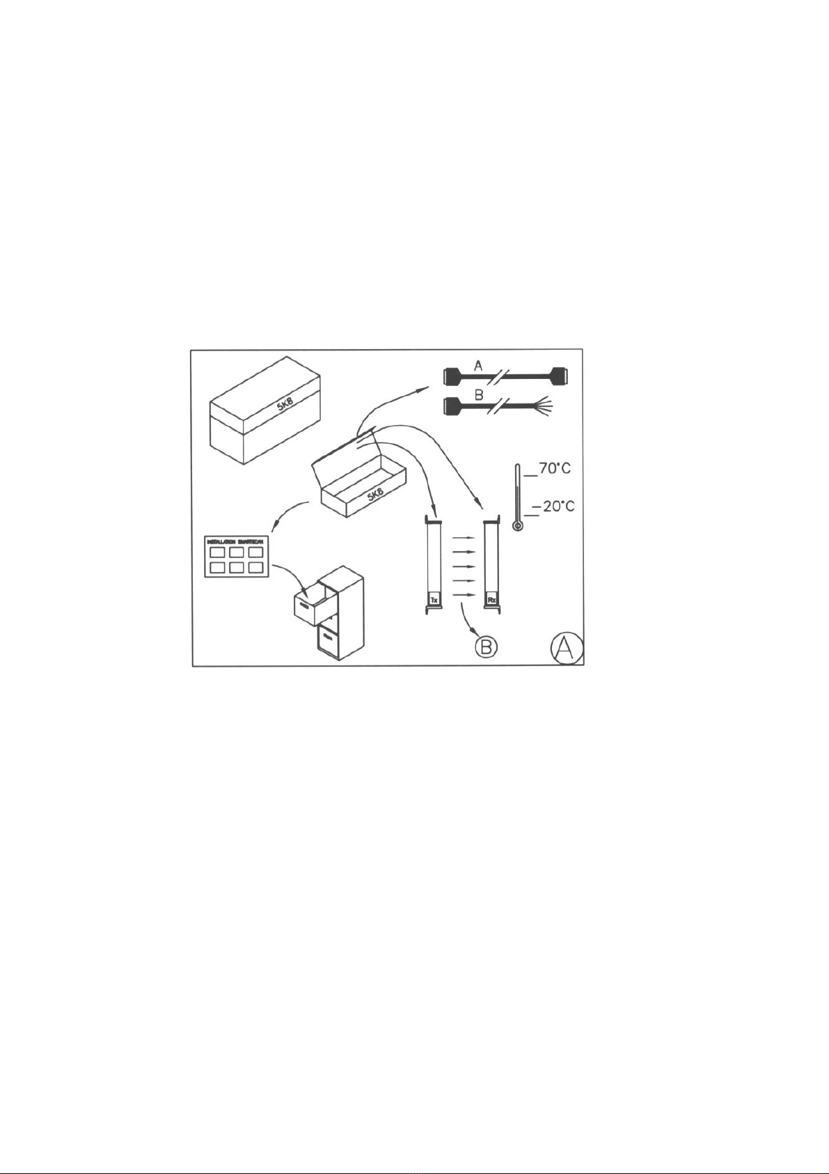
Figure A Unpacking
Remove all packaging material and retain it
Locate and keep the delivery note
Inspect all items for transit damage
Match goods supplied to those specified on the delivery note
Keep the Installation Sheet in a safe place
Each 5K8 system supplied would normally include:
Light curtain
Cables (A) and (B)
Installation sheet
Service questionnaire form
Storage requirements
Humidity -<95%
Temperature range between -20C and +70C

SMARTSCAN 5K8 SERIES LIGHT CURTAIN 2
CD401/130711 INSTALLATION SHEET EXPLAINED
Please note that the Installation Sheet Explained documents are periodically updated. The product Installation Sheets
supplied with the product should be referenced first for current installation information.
Figure B Operating Requirements
Humidity <95%
Temperature range between 0 and 50 degrees C
Vibration frequency <55Hz max. Displacement <0.35mm
Equipment should not be used in potentially explosive atmospheres. The
units are not ‘EX’ rated. Do not use the equipment in explosive
atmospheres. For further information on explosive-proof enclosures contact
Smartscan Ltd.
Noise generated by the equipment will never exceed 70 dB
K -Detection zone width
R -Scanning range of the light curtain
Detection zone width (K) –Must be of a suitable height for each application
to prevent personnel access to the danger area either over, under or around
the light curtains detection zone.
Range (R) –Ensure the particular light curtain specification is capable of
satisfying the range requirement for the application.
Fig. B also shows the connection points for the three different cable options
used with the 5K8 series.
The A (Interconnect) cable has two 25 pin D connector sockets and is
connected between the transmitter (TX) and the receiver (RX) head of the 5K8
series.
The B (User) cable has one 25 pin D connector plug at one end with the other
end consisting of the colour coded wires for the end user to interface into the
machine control system. The B (User) cable is either connected directly onto
the receiver head or to the reset station if used.
SMARTSCAN 5K8 SERIES LIGHT CURTAIN 3
CD401/130711 INSTALLATION SHEET EXPLAINED
Please note that the Installation Sheet Explained documents are periodically updated. The product Installation Sheets
supplied with the product should be referenced first for current installation information.
The X Cable is required if the user has opted to use a Smartscan reset station.
The X cable has two 25 pin D connectors with one end having a socket and
the other end with a plug. The cable is interfaced with the socket end
connected to the Reset station and the plug end connected to the receiver
head of the 5k8 series.
Since the X cable is a 25 pin D type connector with a Plug and Socket, the X
cable can also be used as an extension cable for either A (Interface) cable or
the B (User) cable.
To ensure correct operation of the system cable lengths as stated should not
be exceeded: A cable = 50 metres. B cable = 50 metres. X cable = 10 metres
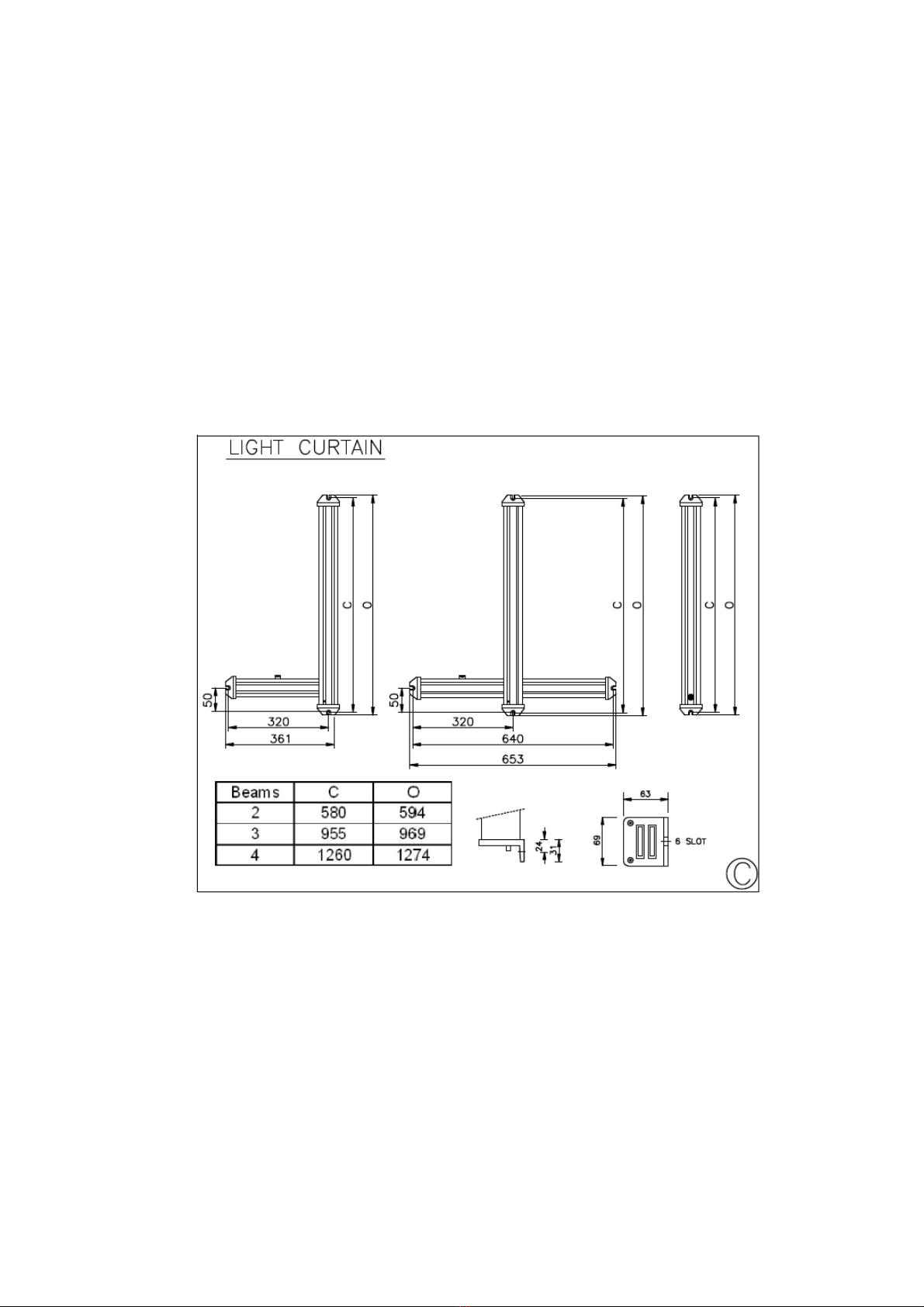
Figure C Mounting and Dimensional Information
The 5K8 series safety light curtain is supplied with mounting brackets fitted as
standard. The mounting brackets are located at the ends of the light curtain as
shown above and 6mm bolts should be used to mount the light curtain in
position.
The table above provides useful mounting measurements for the L, inverted ‘T’
and the straight light curtain.
C = Mounting centres
O = Overall Length
SMARTSCAN 5K8 SERIES LIGHT CURTAIN 4
CD401/130711 INSTALLATION SHEET EXPLAINED
Please note that the Installation Sheet Explained documents are periodically updated. The product Installation Sheets
supplied with the product should be referenced first for current installation information.
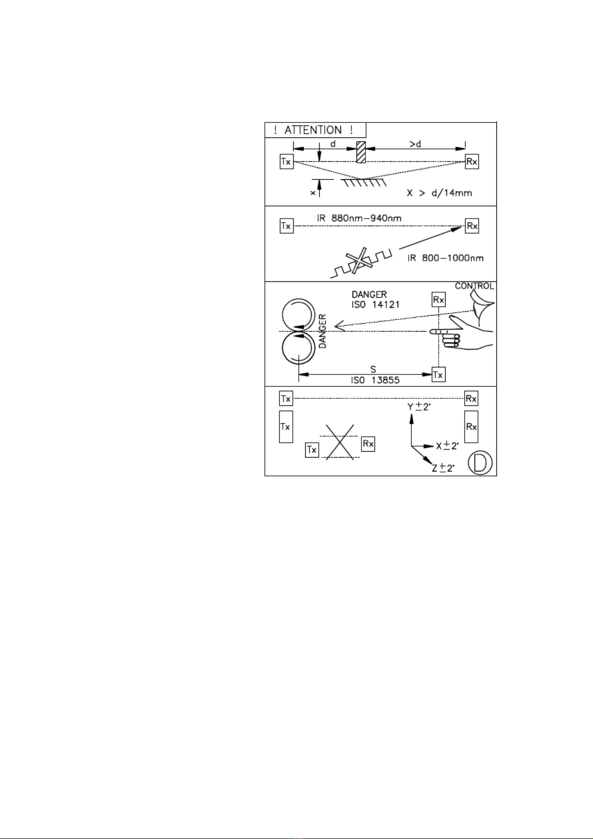
Figure D shows 5K8 Series light curtain end-bracket dimensions. Use M6
bolts for the mounting brackets.
1. Consider reflective
surfaces that may give rise
to an optical ‘short circuit’
from the direct path of the
light curtain’s infrared
beams as shown in the first
illustration of Fig. D. To
ensure the light curtain is
mounted far enough away
from reflective surfaces use
the formula provided to
calculate the minimum
distance (X) between the
light curtain and reflective
surface.
2. To prevent intermittent
tripping of the light curtain
ensure that extraneous
infrared energy between
800 and 1000 nanometres
is not directed towards the
Perspex window of the
receiver unit (RX).
Extraneous sources would
include infrared sensors,
infrared remote controls or
scanning systems.
3. Ensure the mounting position of the light curtain in respect to the nearest
danger point meets the requirements of European Standard ISO 13855.
See Appendix 1.
4. Ensure the light curtain transmitter (TX) and receiver (RX) units are
mounted accurately in-line with each other and are both perpendicular and
parallel to each other within the parameters shown for each axis.
5. If utilising mirrors to deflect the light curtain ensure the mirror length is
50mm longer at either end of the light curtain detection zone width and
mounted centrally to the zone. To ensure reliable operation the light
curtain deflection angle (A) from the mirror must not be less than 40
degrees or greater than 100 degrees.

SMARTSCAN 5K8 SERIES LIGHT CURTAIN 5
CD401/130711 INSTALLATION SHEET EXPLAINED
Please note that the Installation Sheet Explained documents are periodically updated. The product Installation Sheets
supplied with the product should be referenced first for current installation information.
Figure E shows examples of the identification labels that are affixed to the
transmitter (Tx) and receiver (Rx) columns.
SMARTSCAN 5K8 SERIES LIGHT CURTAIN 6
CD401/130711 INSTALLATION SHEET EXPLAINED
Please note that the Installation Sheet Explained documents are periodically updated. The product Installation Sheets
supplied with the product should be referenced first for current installation information.
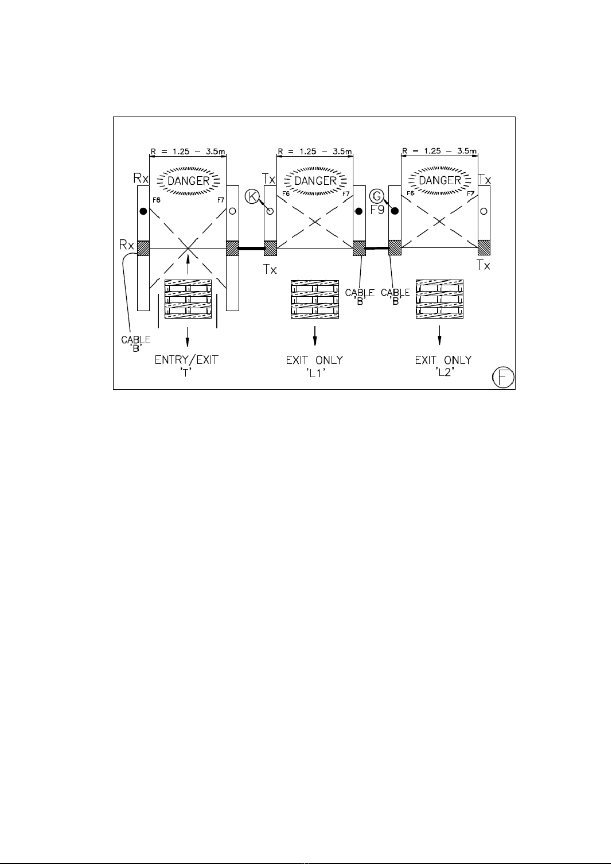
When installing a Smartscan 5K8 Series light curtain your attention is drawn to
the following: (Figure F)
The inverted T 5K8 series light curtain is also known as an entry/exit system.
This system is normally used between two zones (machines) allowing transfer
of the pallets from one zone to the other. The horizontal mute module
provides 2 muting beams at either end of the mute module transmitting infra
red mute beams diagonally across to the receiver side forming a cross beam
muting arrangement.
The system works by the square pallet load moving into the two mute beams
and interrupting them. The two mute beams are monitored with a disparity
timer of two seconds to provide a mute initiation of the light curtain.
The L shaped 5K8 series light curtain is also known as the exit only system.
There are two types of ‘L’ available, right hand (L1) and left hand (L2). The Left
or right hand indicates where the User B cable is connected as shown above.
You will note that the mute cross beams are arranged on one side of the light
curtain. They function in the same format as the T shape explained above.
The cross beams must always be on the Danger side and therefore the pallet
can only travel in one direction moving away from the danger to the safe side
of the machine.
It is a control requirement for the 5K8 series that an additional 3rd mute input is
provided via the conveyor run signal. This signal acts as a permissive signal
to the cross beam mutes and/or external mute input signals.

SMARTSCAN 5K8 SERIES LIGHT CURTAIN 7
CD401/130711 INSTALLATION SHEET EXPLAINED
Please note that the Installation Sheet Explained documents are periodically updated. The product Installation Sheets
supplied with the product should be referenced first for current installation information.
Figure G shows the functions table for the 5K8 series
Safety Outputs (F1) –5K8 series safety light curtains have cross-monitored
output switching relays mounted inside the receiver column. The output relays
provide two safety ‘volt free’ forcibly guided switching contacts which are
internally connected to the wires in the multi-core user cable ‘B’ as follows:
OSSD1 (Output 1): orange (OR) and pink (PK). OSSD2 (Output 2): turquoise
(TU) and grey (GY). Maximum contact switching power 24V DC, 2A or
maximum 110V AC, 2A.
Status Output (F2) -Relay provides one non-safety ‘volt free’ switching
contact which is internally connected to the wires in the multi-core user cable
‘B’, wires red (RD) / black (BK) and red (RD) / brown (BN). The switching relay
contacts are ‘normally open’ outputs from this relay and should only be used
for non-safety applications. Maximum switching power 110V, 1A. The status
relay activates when the safe output relays (F1) turn ON and de-activates
when the safe outputs (F1) turn OFF.
EDM (F4 & F5) (SMM OUT & SMM IN) -An External Device Monitoring
contact signal is provided for the user to monitor external switching devices.
This is to ensure those devices respond in unison with the safety outputs (F1)
each and every time the light curtain is interrupted.
The green (GN) (cable B) wire should be connected to a N/C contact of the
device being monitored. The other side of the EDM switch contact should be

SMARTSCAN 5K8 SERIES LIGHT CURTAIN 8
CD401/130711 INSTALLATION SHEET EXPLAINED
Please note that the Installation Sheet Explained documents are periodically updated. The product Installation Sheets
supplied with the product should be referenced first for current installation information.
connected to the green (GN) / red (RD) wire. If the EDM function is not
required for a particular application it is necessary to link the green (GN) wire
to the green (GN) / red (RD) wire. If the link is not fitted the safety system will
trip and it will not be possible to reset the light curtain.
Mute inputs M1 (F6) and M2 (F7) -Mute inputs M1 (mute 1) yellow (YE) wire
and M2 (mute 2) white (WH) wire are for connecting external muting signals to
the 5K8 safety light curtain. The input signals should come from separate
sources, so that a single fault cannot cause a failure of the protective function.
When using the two external mutes the two mute signals are monitored via the
two second mute disparity timer.
Mute output (F8) –The customer may need an additional mute lamp
indication on the machine as a visual warning for the operator. Connection of
a mute indicator lamp can be made by the wires in the B user cable. Connect
the yellow (YE) / blue (BU) wire to one side of the mute lamp and the other
side of the mute lamp is connected to +24V DC. Maximum switching current
rating is 500mA.
Mute lamp output (F9) –This lamp is integrated within the horizontal muting
arm of the light curtain. The lamp acts as a visual warning indicator and will be
illuminated during a mute condition, i.e. pallet transfer.
Mute enable input (F10) –It is a control requirement for the 5K8 series that an
additional 3rd mute input is provided via the conveyor run signal so as to maintain a
high level of safety integrity. This signal acts as a permissive signal to the cross
beam mutes and/or external mute input signals.
Connection of the 3rd mute input is via the red (RD) / blue (BU) wire to a normally –
open (N/O) ‘volt free’ contact to 0V DC. Contact closed when conveyor running.
Guard Override (F11) –providing the light curtain is in a tripped condition and
the curtain is blocked by a loaded pallet then turning and holding the activate
switch (spring return) to ON will automatically turn-on the safety outputs (F1),
for a maximum period of 3 minutes. As soon as the loaded pallet clears the
light curtain the safety system will automatically reactivate to a ‘fully guarded’
condition and the spring return switch can now be released.
The Activate and Guard Override inputs are available from the user (B) cable.
The yellow (YE) / red (RD) is connected to a normally open switch contact and
the other side of the switch is connected to 0V DC.
Note:
These are for external mute inputs, e.g. inductive loops. When using
a self-muting 5K8 system e.g. inverted ‘T’ shape they are not available.

SMARTSCAN 5K8 SERIES LIGHT CURTAIN 9
CD401/130711 INSTALLATION SHEET EXPLAINED
Please note that the Installation Sheet Explained documents are periodically updated. The product Installation Sheets
supplied with the product should be referenced first for current installation information.
Activate (F13) -A push button or key switch is required, having a N/O switch
contact. Connect the blue (BU) wire from the user cable (B) to one side of the
switch and the other side of the switch to L- (0v dc).
Manual Restart -Turning the ‘activate’ switch to ON and then releasing the
switch will automatically turn on the safety outputs (F1), providing the light
curtain is clear of obstruction.
(RX) Light curtain ‘clear’ indicator (F14) -A green LED indicator mounted on
the receiver unit illuminates when the light curtain is clear of obstruction.
Mute ‘clear’ indicators M1 (F15) and M2 (F16) -Amber LED indicators
mounted on the receiver unit extinguish independently, when mute sensors M1
and M2 are blocked.
(RX) Light curtain ‘block’ indicator (F17) -A red LED indicator mounted on
the receiver unit illuminates when the light curtain is obstructed.
Safe output ‘on’ (F18) -A green LED indicator mounted on the receiver unit
illuminates when the signal output switching relays are ON.
Safe output ‘off’ (F19) -A red LED indicator mounted on the receiver unit
illuminates when the signal output switching relays are OFF.
Status output indicator –(F20) –An amber LED indicator mounted on the
receiver unit is illuminated when the status relay is de-energised, but
extinguishes when the status relay is on.
Mute condition ‘On’ indicator (F21) -Amber LED indicator mounted on the
receiver unit illuminates when the light curtain output relays are in a muted
condition.
(TX) transmitter diode on indicators –(F22). A red LED corresponding to
each transmitter diode is illuminated when each transmitter is operational.
Activate ‘On’ indicator –(F23). A red LED mounted on the receiver unit to
indicate reset switch activation.
EDM ‘On’ indicator –(F24). A red LED mounted on the receiver unit
illuminates when an EDM signal is present.
Mute Enable (ME) ‘On’ indicator –(F25). A red LED mounted on the receiver
unit illuminates when a mute enable (conveyor run) signal is present.
SMARTSCAN 5K8 SERIES LIGHT CURTAIN 10
CD401/130711 INSTALLATION SHEET EXPLAINED
Please note that the Installation Sheet Explained documents are periodically updated. The product Installation Sheets
supplied with the product should be referenced first for current installation information.
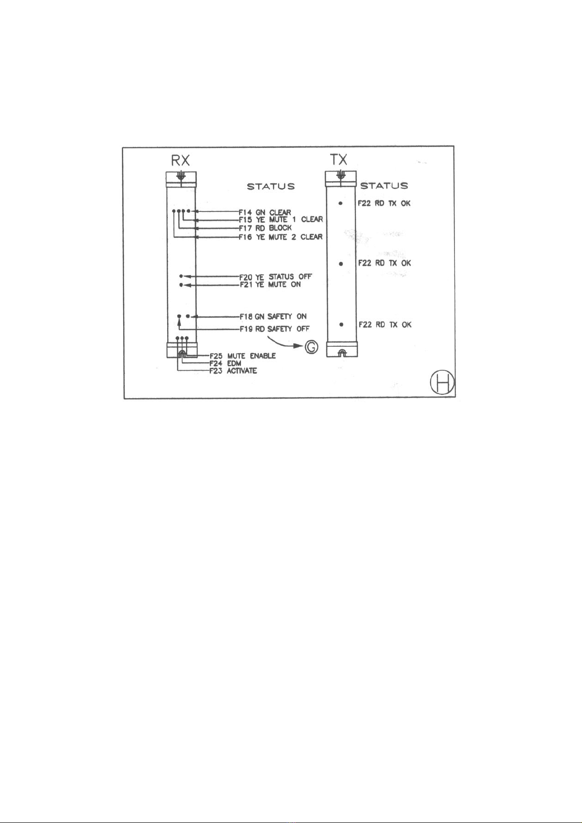
Figure H shows a diagrammatic arrangement of all the function LEDs and
location on the 5K8 series safety light guard. See Fig. G above for a detailed
explanation.
LED Status Indicators on the R/X
F14 Green Guard Clear
F15 Yellow Mute 1 Clear
F17 Red Guard Blocked
F16 Yellow Mute 2 Clear
F20 Yellow Status relay off (Auxiliary / Non-safety Output)
F21 Yellow Mute on
F18 Green Safety outputs on
F19 Red Safety outputs off
F25 Red Mute enable on
F24 Red EDM on
F23 Red Activate on
LED Status Indicators on the T/X
F22 Red Beam(s) transmitting
SMARTSCAN 5K8 SERIES LIGHT CURTAIN 11
CD401/130711 INSTALLATION SHEET EXPLAINED
Please note that the Installation Sheet Explained documents are periodically updated. The product Installation Sheets
supplied with the product should be referenced first for current installation information.
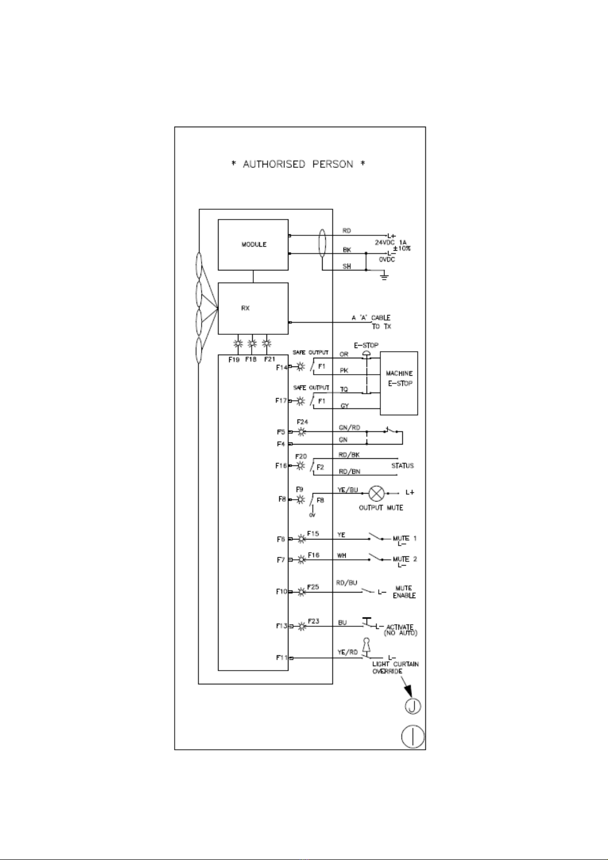
Figure I shows all the input and output connections to and from the 5K8 series.
The drawing also shows the wire colour coding. Please see Appendix 2 for
examples of typical 5K8 series wiring configurations.

SMARTSCAN 5K8 SERIES LIGHT CURTAIN 12
CD401/130711 INSTALLATION SHEET EXPLAINED
Please note that the Installation Sheet Explained documents are periodically updated. The product Installation Sheets
supplied with the product should be referenced first for current installation information.
Power supply -Use a regulated supply +24V DC, 2A ƒ10%. Protect the +24V
input with a 1.5A fuse. Connect the power supply to cable B as follows: The
red (RD) wire to +24V DC and the black (BK) wire to L- V DC. Connect the
screen to ground.
All input and output connections from the Smartscan 5K8 Series are via a plug
connected into the Receiver (RX) head –Cable B (User).
Note:
Prior to initial power up of the light curtain check the following:
Red (RD) / blue (BU) wire ‘mute enable’, is connected to 0V DC
via a 3rd mute signal, e.g. conveyor run.
EDM. Is connected across the N/C contact of the FSD. If not used
link the green (GN) wire to the green (GN) / red (RD) wire.
Note:
Prior to initial power up of the light curtain check the following:
If the Smartscan system is connected directly to a 24V DC source
supplied by the user, it must be emphasised that the supply should be
regulated and suppressed to prevent transient voltages and other forms of
electrical interference from affecting correct operation of the Smartscan
equipment.
SMARTSCAN 5K8 SERIES LIGHT CURTAIN 13
CD401/130711 INSTALLATION SHEET EXPLAINED
Please note that the Installation Sheet Explained documents are periodically updated. The product Installation Sheets
supplied with the product should be referenced first for current installation information.
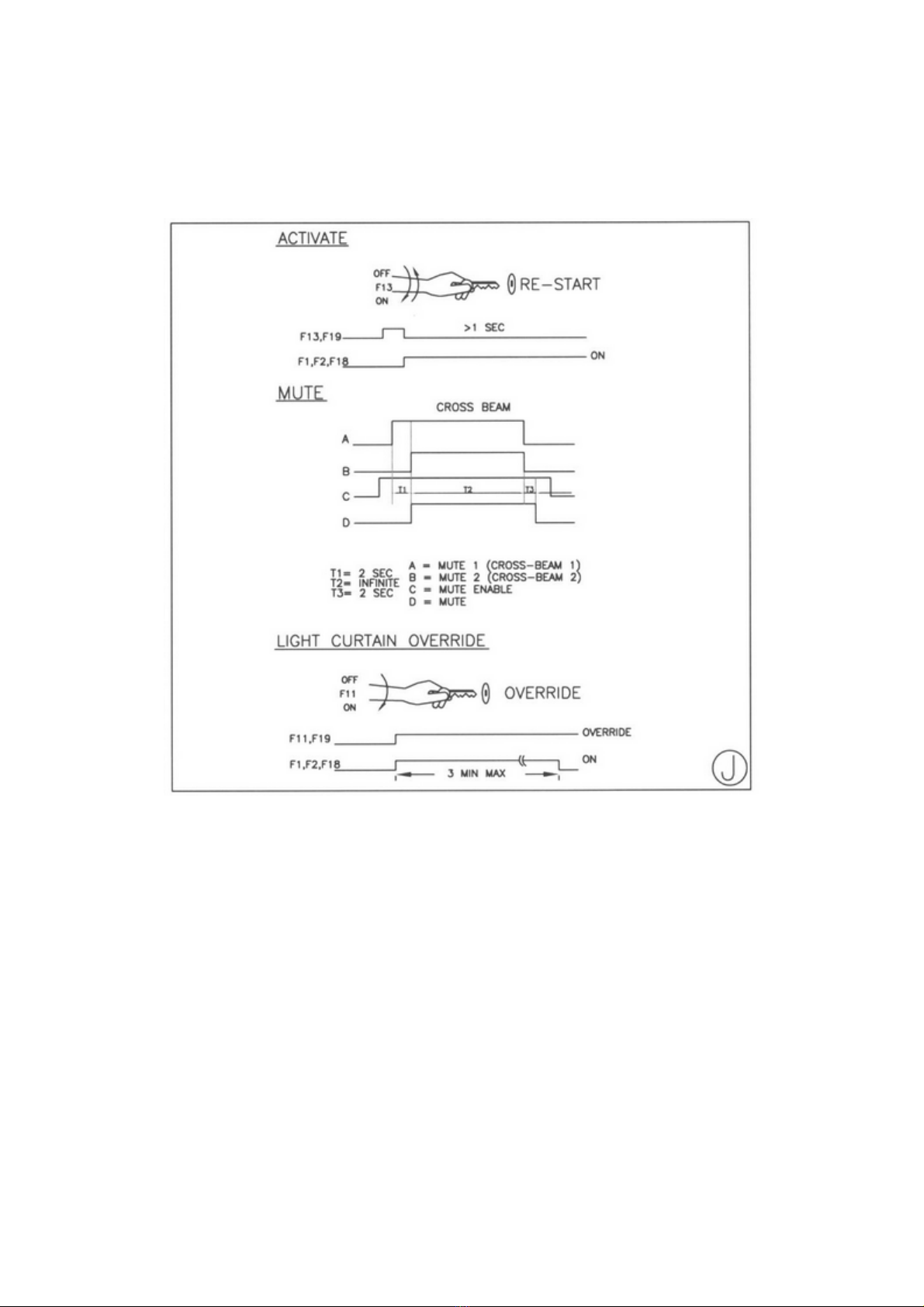
Fig J shows the standard timer functions used in the 5K8 Series for muting
and guard override applications. The timers used in cross-beam muting are
also shown below.
T1 (Mute Disparity Time) –The maximum time allowed between activation of
signals mute 1 (M1) and mute 2 (M2). This is set at 2 seconds.
T2 (Mute Time Out Period) -No overall mute timeout,(infinite).
T3 (Mute Off Delay Time) -A predetermined time that the light curtain will
remain in a muted condition following de-activation of one or both of the mute
signals. This is set at 2 seconds.
It is assumed that the Mute enable signal is energised during the entire
pallet transfer process.

SMARTSCAN 5K8 SERIES LIGHT CURTAIN 14
CD401/130711 INSTALLATION SHEET EXPLAINED
Please note that the Installation Sheet Explained documents are periodically updated. The product Installation Sheets
supplied with the product should be referenced first for current installation information.
Fig. Kshows the on-board dip switches for user to set the light curtain in either
automatic or manual start-up. It is supplied factory set to manual restart mode.
SMARTSCAN 5K8 SERIES LIGHT CURTAIN 15
CD401/130711 INSTALLATION SHEET EXPLAINED
Please note that the Installation Sheet Explained documents are periodically updated. The product Installation Sheets
supplied with the product should be referenced first for current installation information.
Figure L Activate and Guard Override Functions
Manual Restart -At power-up or, following a tripped condition, the activate
switch is used to restart (reset) the output relays to an ON state. The switch
must be activated and released to enable a restart condition.
The reset switch must be located so that the operator cannot reset the light
curtain from inside the dangerous area. In addition the reset switch must be
positioned so that the operator can see that the dangerous area is safe / free
of personnel before resetting the machine.
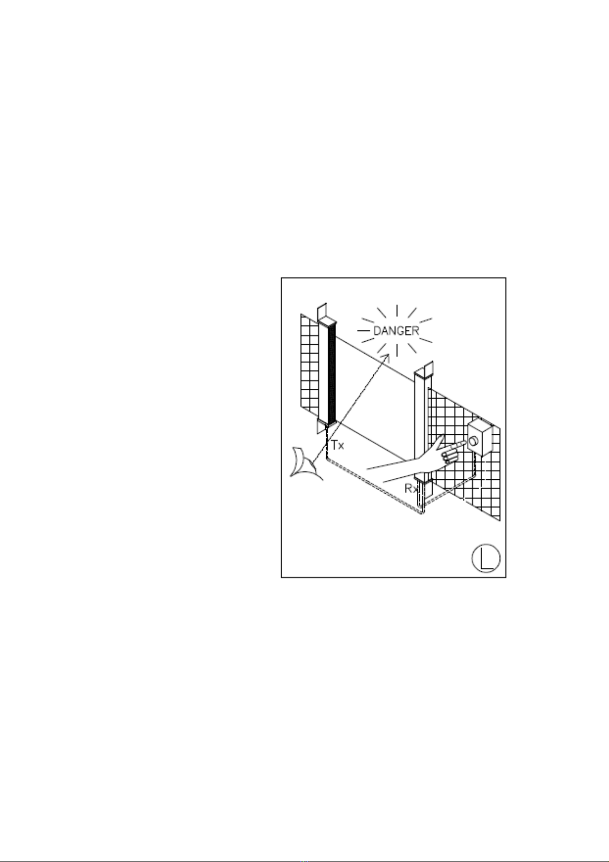
Guard Override -This function should only be used when using the light
curtain to transfer pallet loads from one zone to another.
If the safety system trips when a
pallet load is interrupting the
sensing field of the light curtain
the safety system cannot be
restarted. In order to remove
the blockage from the light
curtain the 5K8 series provides
a guard override facility. This is
achieved by activating and
holding the guard override
switch until the blockage has
cleared the sensing field of the
light curtain. The maximum time
permitted for this is 3 minutes.
However if the time is
inadequate the process can be
repeated by simply releasing the
active switch and re-activating
and holding the switch again.
The guard override switch can
be a push button, preferably a
key switch of the type ‘spring
return’.
Please note that the light curtain’s safety outputs (OSSDs) can only be reset
once the light curtain sensing field is free of the obstruction. Therefore the
override function is only available whilst a pallet load is blocking the sensing
field of the light curtain.
The Restart controls must be located such that the danger area can be
seen to be clear of persons before the system is activated.
SMARTSCAN 5K8 SERIES LIGHT CURTAIN 16
CD401/130711 INSTALLATION SHEET EXPLAINED
Please note that the Installation Sheet Explained documents are periodically updated. The product Installation Sheets
supplied with the product should be referenced first for current installation information.
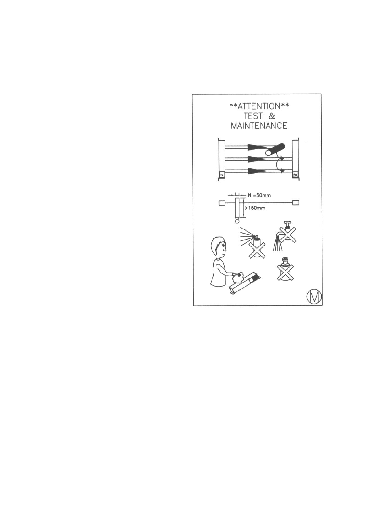
Figure MTest and Maintenance
Power-up the light curtain and activate the output switching circuits to an ON
condition.
Insert a test piece of appropriate size
into the top light beam, 150mm from
the transmitter unit. At this point the
output switches will turn OFF as the
test piece totally obscures the beam.
Repeat this process through each of
the beams in the light curtain.
Ensure that while the test piece is
obscuring each beam the output
switches are OFF.
The test procedure should be carried
out frequently as indicated by the risk
assessment for the particular
installation. Smartscan Ltd
recommends the test should be
carried out daily.
The Transmitter (Tx) and Receiver (Rx) windows should be cleaned regularly
as indicated on the Installation Sheet.
Dirt build up on the windows may lead to intermittent tripping or a totally
blocked condition of the light curtain. Clear adhesive tape may be applied to
the windows of curtains in dirty or abrasive conditions. Renew the clear
adhesive tape periodically.
Clean the windows with a clean damp cloth using a mild detergent. Never use
abrasive, corrosive cleaners or spray detergents.

SMARTSCAN 5K8 SERIES LIGHT CURTAIN 17
CD401/130711 INSTALLATION SHEET EXPLAINED
Please note that the Installation Sheet Explained documents are periodically updated. The product Installation Sheets
supplied with the product should be referenced first for current installation information.
Figure N shows an operations chart for the 5K8 series.
Before installation read and
understand the Installation
Sheet provided paying
particular attention to the
information provided in Figure
D.
Refer to Figure M for test and
maintenance procedures.
Every 24 hours carry out tests
as indicated in Figure M.
Every 6 months check the
entire installation paying
particular attention to Figure D.
If the equipment fails to
operate as intended check the
electrical connections as
shown in Figure I.
SMARTSCAN 5K8 SERIES LIGHT CURTAIN 18
CD401/130711 INSTALLATION SHEET EXPLAINED
Please note that the Installation Sheet Explained documents are periodically updated. The product Installation Sheets
supplied with the product should be referenced first for current installation information.
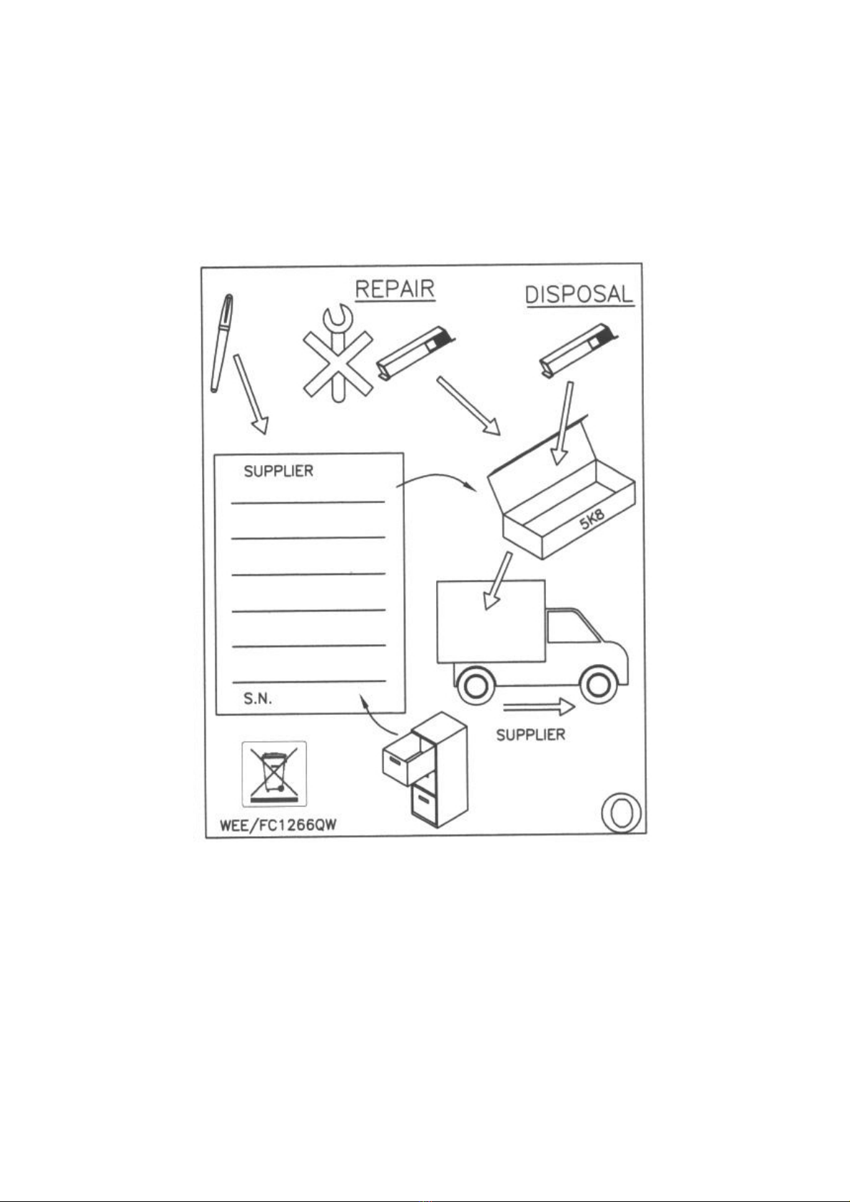
Figure Ooutlines the procedure for returning a Smartscan product.
If a fault occurs that cannot be resolved or the equipment is damaged return the
system to the nearest Smartscan distributor or Smartscan Ltd. Indicate the
nature of the fault and the symptoms displayed on the form provided.
Returned guards must be matching serial number pairs. This is to
ensure that the Service department can carry out a full and proper
inspection of the returned light curtain system.
SMARTSCAN 5K8 SERIES LIGHT CURTAIN 19
CD401/130711 INSTALLATION SHEET EXPLAINED
Please note that the Installation Sheet Explained documents are periodically updated. The product Installation Sheets
supplied with the product should be referenced first for current installation information.
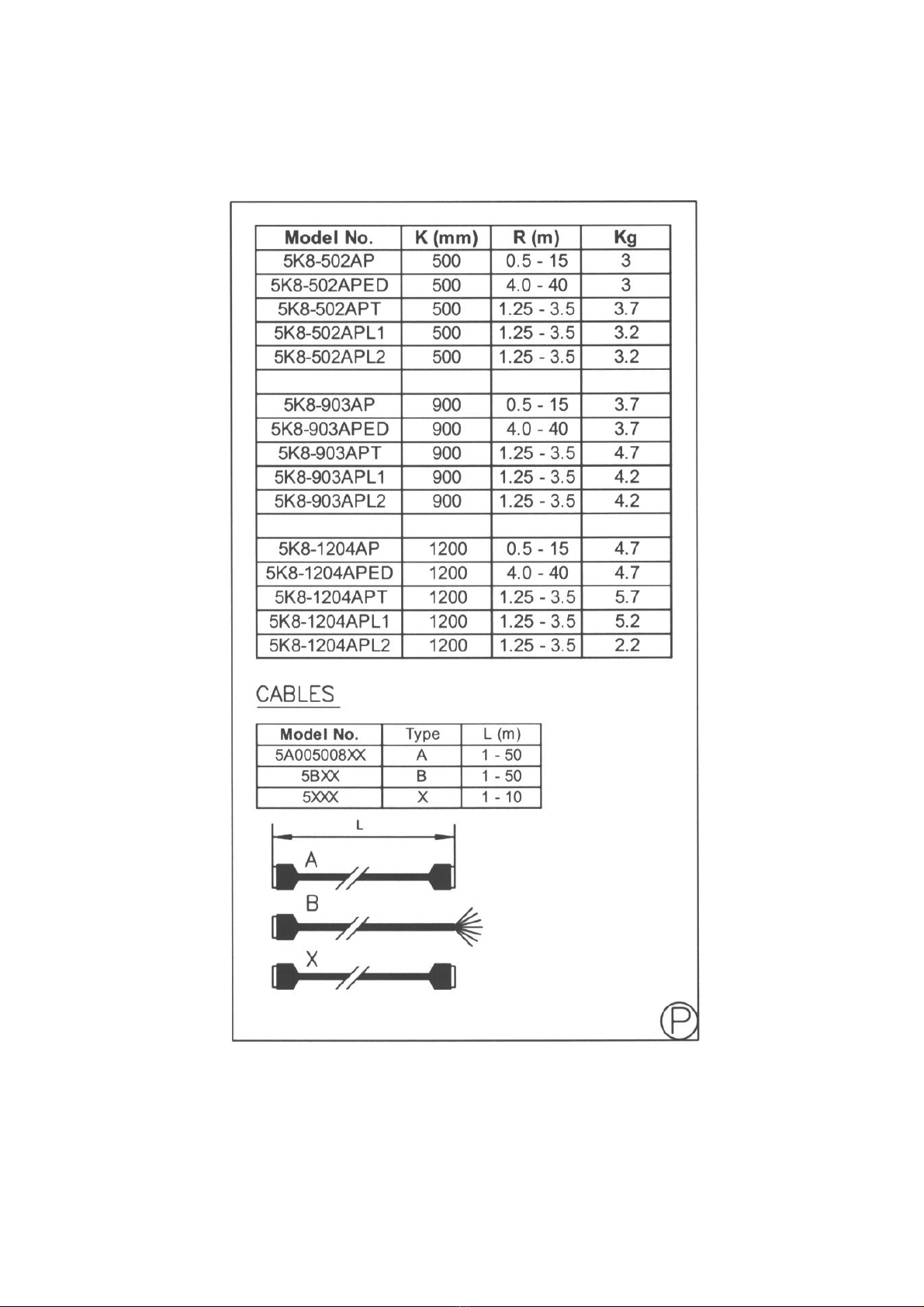
Figure Pshows a list of the model numbers and cable types. It describes the
detection zone width (K), the maximum scanning range and weights for the
5K8 series.

SMARTSCAN 5K8 SERIES LIGHT CURTAIN 20
CD401/130711 INSTALLATION SHEET EXPLAINED
Please note that the Installation Sheet Explained documents are periodically updated. The product Installation Sheets
supplied with the product should be referenced first for current installation information.
Figure Qshows a copy of the 5K8 series declaration of conformity.
This manual suits for next models
2


