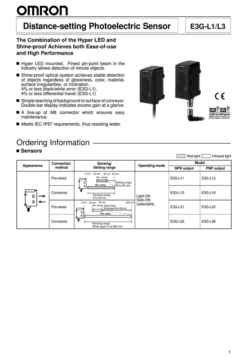
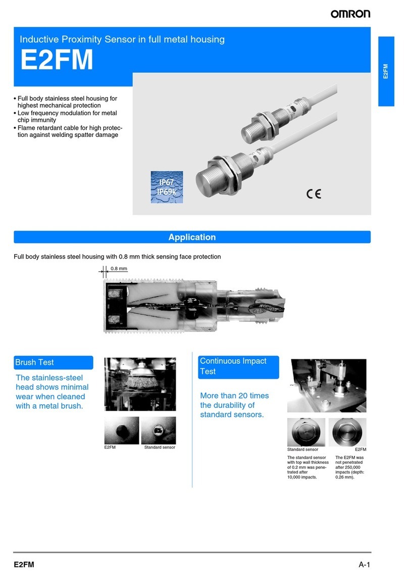
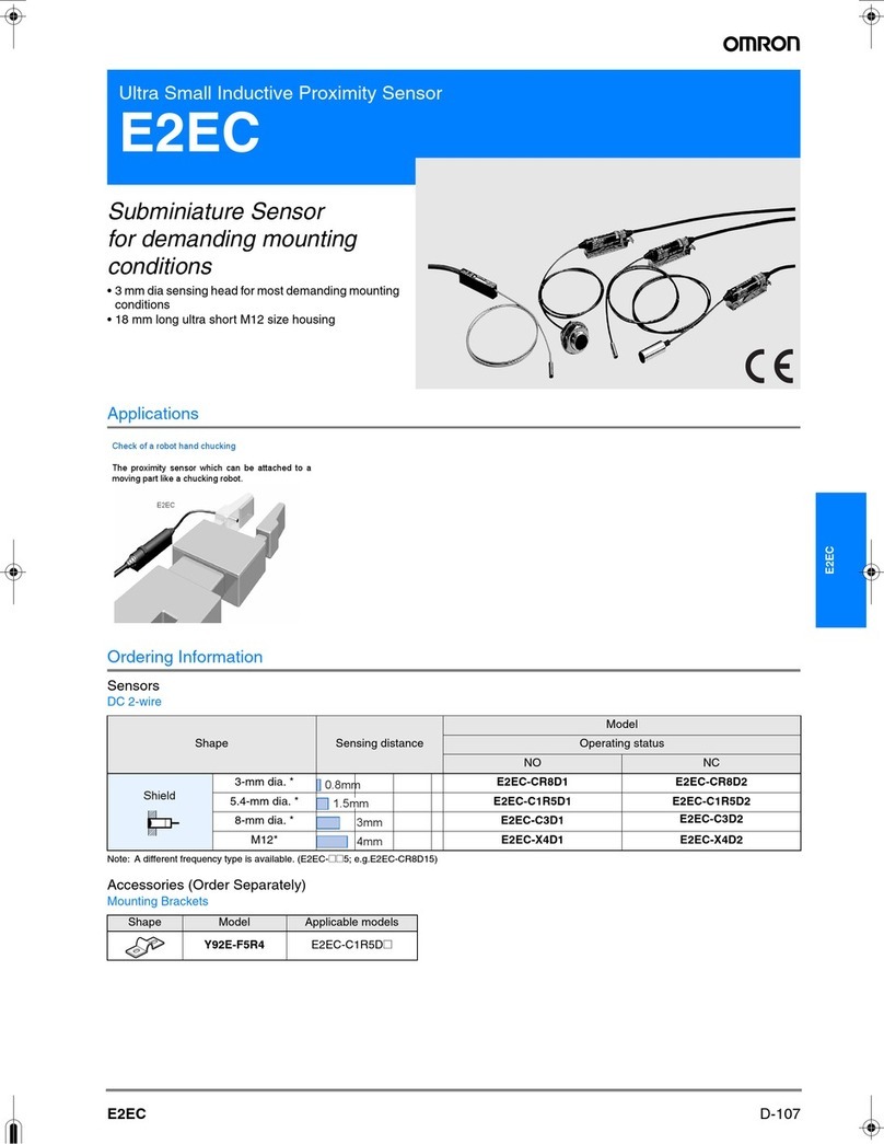
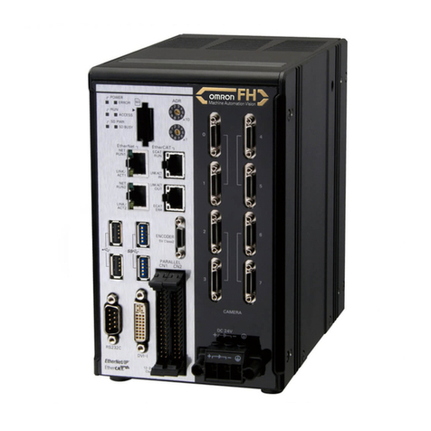
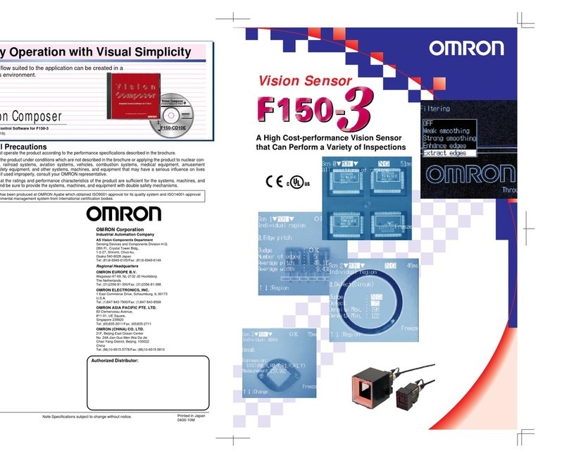
Omron F160 Vision Sensor User manual

F160
C-25F160
Vision Sensor
F160
Impressive high speed opens up new
possibilities
F160
High-
speed
Adaptability
New
inspection
function
Simple
operation
Features
Can be applied to ultra-fast manufacturing lines. Full range of detection features within the
required cycle time. Contributes to improved detection quality.
The newly developed double-speed camera makes it possible to read in images as much as 4 times faster than previous speeds,
and also achieves an impressive image processing speed 2 to 10 times faster than previous speeds. For example, using dark-light
search processing in Figure 1, the camera can be used on ultra high-speed lines handling approximately 5000 pieces per minute.
Because each single inspection is fast, multiple inspection tasks can be carried out with minimal increase in time. Inspection tasks
that were previously impossible due to insufficient time can also be added for a big contribution to inspection quality.
Example: Gray Search Processing (Picture 1)
Example: More than one inspection item
F160
Existing
products
Up to 4 times as fast
Image capture time Inspection processing time
2 to 10 times as fast
F502-EN2-04.book Seite 25 Dienstag, 26. Juli 2005 5:48 17

C-26 Vision Systems
Features
Equipped with a memory card for low-cost intro-
duction on multi-type lines and a dramatic in-
crease in the number of scenes. Moreover, this is
a single-stand system, thus, easily implemented.
The F160 unit is equipped with a memory card slot. The scene
number can be easily increased by simply inserting a card.
For example, a 128-MB card can store approximately 1000
scenes. (*) No more need to build a scene data communica-
tion system using computers.
* The number of scenes that can be stored varies depending on the scene set-
tings.
Enhanced image memory function
Up to 35 measurement images or failure images can be
stored. The most recent failure image can be displayed while
measurement continues, enabling analysis of the failure with-
out stopping the line.
I/O monitor
The status of the input/output terminals can be displayed as a
list. This is a big help for a wiring check during adjustment.
Screen capture function
Menu setting screens, measurement screens, and failure im-
ages can be captured and stored in the memory card. These
images can be used in manuals and reports created on a
computer.
Wide range of camera variations
In addition to the double-speed camera, our F150 camera can
also be connected. This lets you select the optimum camera
for your speed, cost, and lighting needs.
NG0
NG1
NG34
Good product image
Improper product image
Setting screen
Documentation on computers
Capture
Memory card
POWER
SYNC
Setup Manual
Procedure
1.#####
###
2.######
####
3.######
######
#####
Double-speed camera
F160-S1/S2/SLC20/SLC50
F150 camera
F150-S1AESLC20/SLC50ESL20A/SL50A
Eight shutter speeds can be selected
from the controller. An intelligent-light-
ing type is also available.
Compact and affordable. Intelligent
lighting and small LED lighting types
are also available.
F502-EN2-04.book Seite 26 Dienstag, 26. Juli 2005 5:48 17

F160
C-27F160
Features
Menu masking function
Menu items that should not be changed on-site can be hidden
to prevent incorrect operation. This also improves operability
and saves time when changing menu settings.
Password function
Operation access can be limited
to personnel who have been is-
sued a password. This contrib-
utes to increased security.
Screen messages
Change to the language used on-site. Can be displayed in
any position on the screen.
Graphic drawing func-
tion
This allows you to draw straight
lines, rectangles, cross-hair cur-
sors, and other graphics. Graph-
ics can be drawn on
measurement positions as well.
RS-232C format
The output format can be
changed to meet the specifica-
tions of the system.
Short-cut key function
Frequently used operations can be assigned to special keys
on the console. Switch menus at the touch of a key.
The character size can be selected, and
even highlighting is possible.
Color display function
Colors can be added to displayed messages and graphics for
easier viewing.
Dialog menu
Dialog-type menus allow even beginners an easy perfor-
mance of settings.
Operation
Screen
Output
Measurement image Line-brightness display
Switch the display
with one touch
X: 135.644
Y: 215.957
X: 135.644
Y: 215.957
F502-EN2-04.book Seite 27 Dienstag, 26. Juli 2005 5:48 17

C-28 Vision Systems
Features
QUEST Character Recognition
F160 uses OMRON's character recognition system - QUEST.
Features
• The user does not have to register characters.
• High discrimination level of similar characters.
• Adapts to fluctuations in shape and size.
"Variable Box" Measurement for Defect In-
spection
The measurement area can be set to change automatically
when performing inspections for objects with varying sizes,
such as electronic chip components. This feature ensures
that the optimum measurement areas are always used for in-
spection.
Flexible Search
This method performs a matching using more than one refer-
ence image and so F160 can perform inspection for objects
with varying shapes. This feature helps to reduce incorrect
evaluations.
Rotation search
This function rotates the image while searching. Processing
speed is 10 times higher than previous models. Angle interpo-
lation enables high-precision angle detection.
Classification
A search is performed using multiple stored models, and the
best-matching model number is output. The flexible search
function can also be used for work shapes.
Can handle variations in shape.
Edge width
The positions of both edges of an ob-
ject are detected with high accuracy,
and from this the width of the object
is calculated. It is not necessary to
set expressions for calculating the
width.
Position displacement
compensation
F160 permits compensation using only
the outline of the object, 2-stage posi-
tion compensation, and setting priori-
ties for the compensation direction.
Labeling
The number of labels (i.e., objects) inside the measurement
area is counted. After they have been sorted according to
area or center of gravity, the measurement data for specified
labels is output.
Expressions
Evaluation and data output based
on a maximum of 32 expressions is
possible. Up to 32 variables (repre-
senting other expressions) can be
used, enabling more complex cal-
culations.
Use for any type of character
The inspection region automatically
adapts to the object size.
Measurement screen
Set frames for adjusting
the region size
Setting screen
Matching can be performed for products with varying shapes
by using more than one reference image.
Example: Searching in a rotation range of 360˚ with a skipping angle of 5˚.
1
2
3
M
S
L
MS
L
Model1 Model2 Model3
Compensation in the X direction followed
by compensation in the Y direction.
Counting gears
Inspecting the position and
number of buttons
F502-EN2-04.book Seite 28 Dienstag, 26. Juli 2005 5:48 17

F160
C-29F160
Ordering information
Name Model Remarks
Controller F160-C10E-2 NPN Input/Output
Controller F160-C15E-2 PNP Input/Output
Double-speed
camera
Camera with intelligent
lighting
F160-SLC20
F160-SLC50
Camera only F160-S1
F160-S2 With partial scan function.
Compatible F150
cameras
Camera with intelligent
lighting
F150-SLC20
F150-SLC50
Camera with light F150-SL20A
F150-SL50A
Camera only F150-S1A
Console F160-KP
F150-KP
Color LCD monitor F150-M05L
Monochrome CRT Video monitor F150-M09
Memory card F160-N64S(S) Memory capacity 64 MB
Camera cable F150-VS
For Double-speed Camera and compatible
F150 Cameras.
Cable length: 3 m*1
*1. Other length on request
Monitor cable F150-VM Cable length: 2 m*1
Parallel cable F160-VP Loose-wire cable for parallel I/O connectors.
Cable length: 2 m
F502-EN2-04.book Seite 29 Dienstag, 26. Juli 2005 5:48 17

C-30 Vision Systems
Rating/Performance
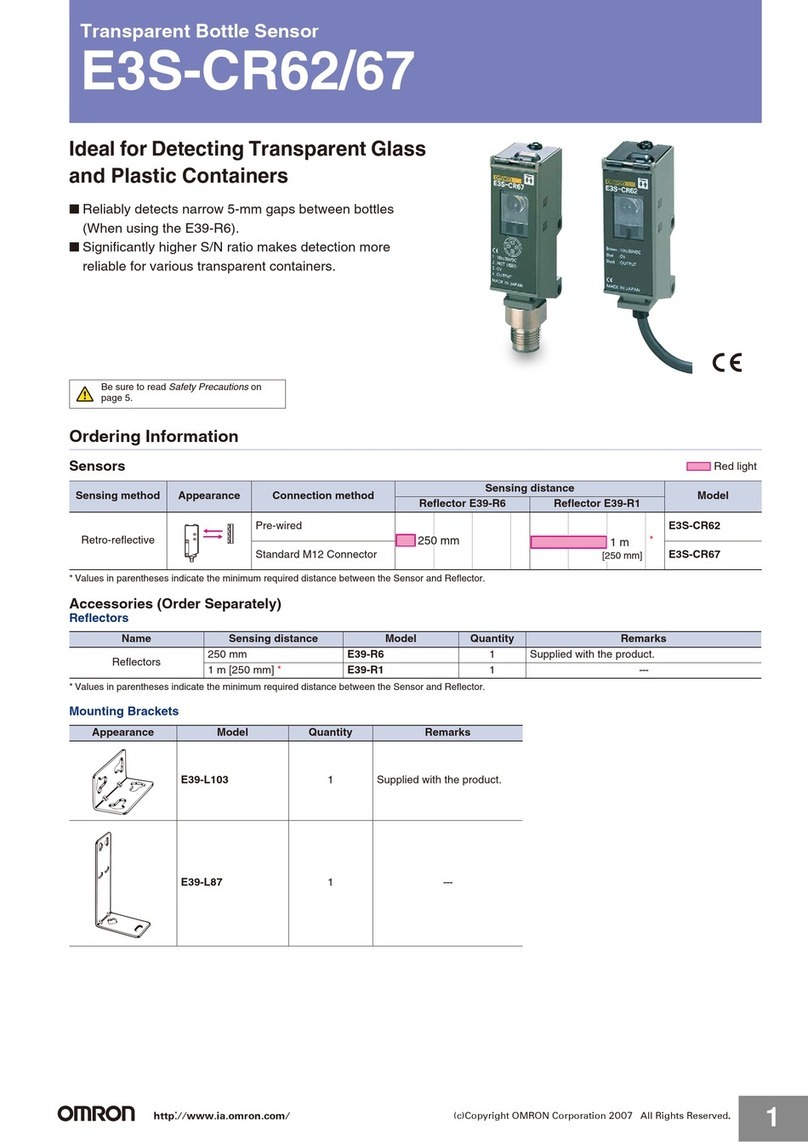
Controller: F160-C10E-2/F160-C15E-2
Item Specifications Conversational Menu Mode Expert Menu Mode
Connectable cameras F150-S1A/SL20A/SL50A/SLC20/SLC50, F160-S1/S2/SLC20/SLC50, etc.
Number of cameras connect-
able 12
Number of pixels 512 x 484 (H x V)
Number of scenes 32 scenes (Expansion possible using Memory Card)
Image storage function Maximum of 35 images stored
Filtering ---
Smoothing (strong/weak), edge enhancement,
edge extraction (horizontal, vertical, both horizontal and
vertical), dilation, erosion, median, background suppres-
sion
Position displacement com-
pensation
Set either automatically or manually
Compensation directions: X, Y, and (360°)
directions
Compensation
directions: X, Y, and (360°)directions
Detection methods: Binary center of gravity, axis angle, labeling, rotation
search, gray search, edge position
Number of measurement
regions 32 regions per scene
Applications
7 types available (presence, orientation, di-
mensions,defects, conformity, position,
chips and burs
---
Measurement data Automatically selected according to the ap-
plication
Gravity and area, gravity and axis, gray search, precise
search, rotation search, flexible search, relative search,
defect, area (variable box), defect (variable box), edge po-
sition, edge pitch, edge width, density average, labeling,
OCR for 1 character, classification
Data operation functions (ex-
pressions) ---
Number: 32 expressions can be set for judgements,
data, and variables used in other expres-
sions.
Operations: Arithmetic operations, square root, absolute
value, remainder, distance, angle, maximum,
minimum, SIN, COS, ATAN, AND, OR, NOT
Result output Overall judgements, judgements for each
measurement region
Overall judgements, judgements for each measurement
region, expression results, measurement/expresion data
Functions for customizing op-
erations --- Menu masking , password setting, shortcut keys
Functions for customizing
screens ---
Display items: Character strings (measured values,
judgement results, times, user-specified
characters, measurement region names)
Specified parameters: Display color, position, size
Number of slots for Memory
Cards 1
Monitor interface 1 channel (color, monochrome)
Serial communications RS-232C/422A 1 channel
Parallel I/O 13 inputs and 22 outputs including control I/O points
Input/
Output type
NPN F160-C10E
PNP F160-C15E
Power supply voltage 20.4 to 26.4 VDC
Current consumption Approx. 1.6 A (when two F160-SLC50 Cameras connected)
Ambient temperature Operating: 0 to 50°C, Storage: -25 to 65°C (with no ice formation or condensation)
Ambient humidity Operating and storage: 35 to 85% (with no condensation)
Dimensions 56 x 160 x 110 (W x H x D) mm (not including connectors and other protruding parts)
Weight Approx. 570 g (Controller only)
F502-EN2-04.book Seite 30 Dienstag, 26. Juli 2005 5:48 17

F160
C-31F160
Double-speed camera: F160-S1/S2
Monitor
Picture element 1/3“ Interline CCD
Effective pixels 659 x 44 (H x V)
Scanning method 1/60-s non-interlace (frame) mode, 1/120-s 2:1 interlace (field) mode
Shutter Electronic shutter; select from 8 shutter-speed settings (1/120 to 1/20,000 s) using menu
Camera with Intelligent Light-
ing F160-SLC20 (field of vision: 20 mm), F160-SLC50 (field of vision: 50 mm)
Ambient temperature
Operating: 0 to +50°C
Storage: -25 to +60°C
(with no icing or condensation)
Ambient humidity Operating and Storage: 35 to 85% RH (with no condensation)
External Dimensions 31 x 40 x 54.5 (W x H x D) mm (not including connectors and other protruding parts)
Weight Approx. 85 g (Camera only)
Item
Model number
Name
F150-M05L
Color LCD monitor
F150-M09
Monochrome CRT Video Monitor
Size 5.5 inches 9 inches
Type Liquid crystal color TFT CRT monochrome
Resolution 320 x 240 dots 800TV or min. (at center)
Input signal NTSC composite video (1.0 V / 75 )
Power supply voltage 20.4 to 26.4 VDC 100 to 240 VAC (-15%, +10%)
Current consumption Approx. 700 mA Approx. 400 mA
Ambient temperature
Operating: 0 to +50°C
Storage: -25 to +65°C
(with no icing or condensation)
Operating: -10 to +50°C
Storage: -20 to +65°C
(with no icing or condensation)
Ambient humidity Operating or storage: 35% to 85%
(with no condensation)
Operating or Storage: 10% to 90%
(with no condensation)
Weight (Monitor only) Approx. 610 g Approx. 4.5 kg
Accessories Instruction manual and 4 mounting brackets Instruction manual
F502-EN2-04.book Seite 31 Dienstag, 26. Juli 2005 5:48 17
C-32 Vision Systems
System configuration
Sync sensor
Programmable Controller
Double-speed Camera
Camera with Intelligent Lighting
F160-SLC20
F160-SLC50 Parallel Cable
F160-VP
Camera
Cable
F150-VS
Compatible F150 Cameras Power
supply
Camera with Light
F150-SL20A
F150-SL50A
Camera with Intelligent Lighting
F150-SLC20
F150-SLC50
Camera
F150-S1A
Console
F150-KPF160-KP
Monitor Cable
F150-VM
Monitor
Monochrome CRT
Video Monitor
F150-M09
Color LCD Monitor
F150-M05L
Camera
F160-S1/S2
Controller
F160-C10E-2
F160-C15E-2
Memory Card
F160-N64S (S) (64 Mbytes)
F502-EN2-04.book Seite 32 Dienstag, 26. Juli 2005 5:48 17
F160
C-33F160
Name and function of each part
F160-C10E/F160-C15E
A
POWER LED
Illuminates while the power is on.
B
RUN LED
Illuminates while the system is in measurement
mode.
C
ERROR LED
Illuminates when a problem occurs.
D
Input terminal (control line)
Connects to a synchronous sensor or program-
mable controller.
E
Input/output connector (data line)
Connects to a synchronous sensor or program-
mable controller.
F
Power terminal
Connects to the power supply.
G
Memory card LED
Illuminates during memory access.
H
Console connector
Connects to the console.
I
Memory card slot
A memory card inserts into this slot.
J
CAMERA 0 connector
Connects to a camera.
K
CAMERA 1 connector
Connects to a camera.
L
RS-232C/422 connector
Connects to a computer or programmable controller.
M
Monitor connector
Connects to a monitor.
N
Ground terminal
Connect the ground wire to this terminal.
A
B
C
D
E
F
G
H
I
J
L
K
M
N
F502-EN2-04.book Seite 33 Dienstag, 26. Juli 2005 5:48 17
C-34 Vision Systems
Function menu
Menu structure diagram
SET
SAVE
TOOL
SYS
RUN
MON
Start
Ref image
Region
Position
End
Chip/Bur
Position
Conform
Surface
Dimns'n
Orient'n
Presence
Up to 32 regions
can be set.
* Cannot be used with
conversational menus.
Camera settings
Output *
Display
Operation settings
Measurement control
Startup mode
Date/Time
System information
Communications
MON
RUN
SYS
TOOL
SAVE
Expression
Display
Camera setting
Communications
Output
Display
Operation settings
Measurement control
Switch menu
Startup mode
Date/Time
System information
Gravity and area
Gravity and axis
Defect
Area (var. box)
Defect (var. box)
Edge position
Edge width
Edge pitch
Density data
Gray search
Precise search
Rotation search
Flexible search
Classification
Relative search
Labeling
OCR for 1 chara
Variable (0 to 31)
Judge (0 to 31)
Data (0 to 31)
SET Adjust
Position
Measurement
One camera connection:
0 to 31
"Two camera connection:
CAMERA 0: 0 to 15
CAMERA 1: 16 to 31"
Shutter Speed
Light control
Filtering order (Position)
Filtering (Position)
BGS levels (Position)
Filtering order (Measurement)
Filtering (Measurement)
BGS levels (Measurement)
1st direction
2nd region (P2, P3)
2nd direction
3rd region (P4, P5)
3rd direction
4th region (P6, P7)
4th direction
Calibration
1st region (P0, P1) Gravity and area
Gravity and axis
Edge position
Gray search
Rotation search
Labeling
These items appear only when 2 Cameras are connected.
Dialog menu Expert menu
F502-EN2-04.book Seite 34 Dienstag, 26. Juli 2005 5:48 17
F160
C-35F160
Dimensions (Unit: mm)
Controller
F160-C10E/F160-C15E
Console
F160-KP
F150-KP
Double-speed camera
F160-S1/S2
F160-SLC20 (with F150-LTC20 intelligent lighting)
F160-SLC50 (with F150-LTC50 intelligent lighting)
Video monitor
F150-M09
38
7 153
66.5 66.5
66.5 66.5
992
110
Four M3 mounting holes with depth of 6 mm
Four M3 mounting holes
with depth of 4.8 mm Four M3 mounting holes
with depth of 4.8 mm
12 60 56 60 12
SHIFT
ENT
F1
F2
F4
F5
F6
F7
F8
F9
F3
ESC TRIG
135.5
20
(29.7)
200040
12 dia.
48
ESC TRIG
SHIFT
CONSOLE
ENT
50
232000 5 10
131.5
87
12.5
12 dia.
(6.2)
(30.7)
(21.7)
2911
(6.2)
31
Light connector (8.8 dia.)
Camera cable connector
(11.8 dia.)
8
30.5
8 (46.5)
(15.5) 54.5
(6)
(14.5)
1"-32UN-2A
(C mount)
20±0.1
21.25
±
2
31.25±2
Two M4 mounting holes
with depth of 8 mm
1/4-20UNC with depth of 8 mm
(23.25)
(13.25)
4 dia.
(85)
(10) 25
46.573
70
12
2.52.5 70
42.5
12
12 12 30.5 8
31
40 (23.25)
(13.25)
20±0.3
(86.25)
(96.25)
Two M4 mounting holes
with depth of 10 mm
1/4-20UNC with depth of 10 mm
90
31
60
16
16 16
16
2.5
90
2.5
52.5
4 dia.
80 46.5 (85)
(10) 25
830.5
(93.25)
(103.25) (23.25)
(13.25)
20±0.3
Two M4 mounting holes
with depth of 10 mm
1/4-20UNC with depth of 10 mm
POWER
SYNC
143
(145)
(155)
132
(46 max.)
Mounting plate thickness: 1.6 to 4.8
(100)
185
(5.5)
Mounting bracket
Monitor cable (F150-VM)
Tolerance:±1 mm
The dimensions in parentheses
are reference values.
133.5
175.5
Panel cut figure
+0.5mm
0
+0.5mm
0
174
42.2
50min
LCD monitor
F150-M05L
222 250
2335
143
190 160
22
50
F502-EN2-04.book Seite 35 Dienstag, 26. Juli 2005 5:48 17
C-36 Vision Systems
In the interest of product improvement, specifications are subject to change without notice.
ALL DIMENSIONS SHOWN ARE IN MILLIMETERS.
To convert millimeters into inches, multiply by 0.03937. To convert grams into ounces, multiply by 0.03527.
Cat. No. Q04E-EN-02
F502-EN2-04.book Seite 36 Dienstag, 26. Juli 2005 5:48 17
Other manuals for F160 Vision Sensor
5
Table of contents
Other Omron Accessories manuals

Omron
Omron E3S-LS10XE4 2M User manual

Omron
Omron ZS-HLDS5T User manual

Omron
Omron E3S-LS3 User guide

Omron
Omron ZS-HLDS2VT User manual

Omron
Omron E2K-F User manual

Omron
Omron FZ3 Series User manual

Omron
Omron F210 User manual

Omron
Omron FQ-CR2 Series User manual

Omron
Omron ZFV-C Installation manual

Omron
Omron E2K-L User guide

Omron
Omron E2EM User manual

Omron
Omron FQ-AC Series User manual

Omron
Omron F400 User manual

Omron
Omron ZFX-C10 COMMUNICATION Operating manual

Omron
Omron ZJ-SD Series User manual

Omron
Omron E3Z-LT User manual

Omron
Omron fz5 series User guide

Omron
Omron ZS-HLDS60 User manual

Omron
Omron E2E - 2 User manual

Omron
Omron F150-2 User manual