smart Wallbox Introducing the product 5
‡ Introducing the product.
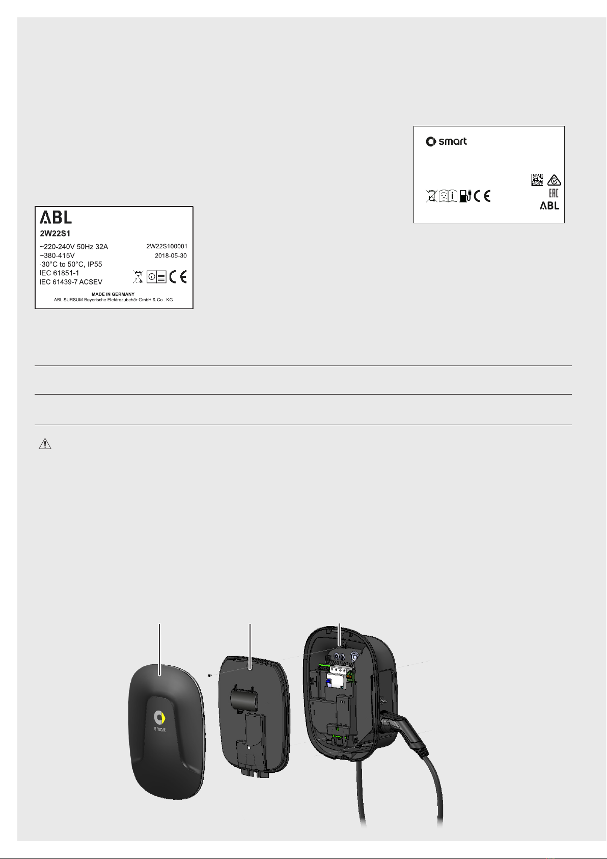
The smart Wallbox Home is entirely manufactured in Germany and at all times complies with the regulati-
ons and norms for the charging of electric vehicles applicable throughout Europe according to IEC 61851-1,
Mode 3 – please also refer to the section on „Guidelines & Norms.“ on page 28. According to their requi-
rements, users may select from model variants with a range of charging outputs and fixed charging cable
with Type 2 charging plug, which are designed for domestic and semi-public applications.
We place the highest value on user safety in all our products. For this purpose, your Wallbox features an
internal Type A RCCB and integrated DC fault current detection, which, in combination with the protective
measures of your domestic power supply and of your electric vehicle, effectively protects from short cir-
cuit, electric shock and other operational hazards.
The Wallbox is especially easy to operate during everyday use: A multi-colored LED display in the lower
part of the housing cover allows you to check the current operating status at any time. Should a mal-
function occur, you can identify the cause by the specific error code displayed by the multi-colored LED
without having to open the housing of the Wallbox. After being taken into operation by a specialist con-
tractor, the smart Wallbox Home is ready for charging at any time, while each charging process must be
separately authorized via the integrated key switch.
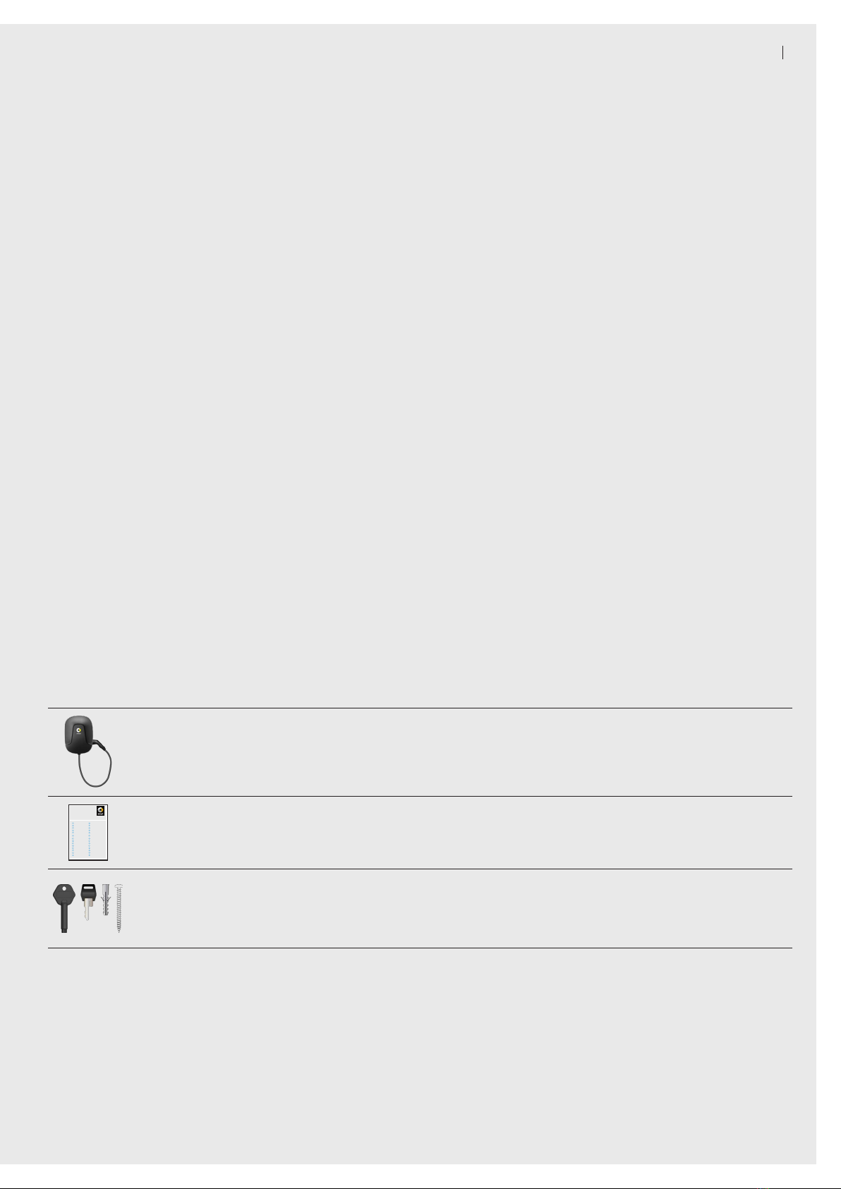
Unpacking and components included.
The smart Wallbox Home package includes a range of accessory components needed for installation and
proper operation. Therefore, please check immediately after unpacking whether the following components
are included:
Component Quantity Description
Wallbox 1
Charging station consisting of housing base with integra-
ted electronic unit, internal electronic components cover and
housing cover
smart Wallbox
Home
DE »Sicherheitshin weise&
Kurzanleitung. BG »Ука зания за безопасности
кратко ръководство.
EN »Safet yinformation &
QuickStart Guide . GR »Οδηγίες ασφαλείας &
Συνοπτικό εγχειρίδιο.
FR »Consignes de sécurité &
Guidede prise en main.HR » Sigurnosne napomene i
kratkeupute.
IT »Avvert enze disicurezza &
brevii struzioni.PL » Wskazówki bezpieczeństwa &
Skróconainstrukcja o bsługi.
NL »Veili gheidsinstructies &
verkorte handleiding. RO » Indicaţii de sigur anţă&
scurtîndrumar.
PT »Indic açõesde segurança e
GuiaRápido. RU
»Указания по т ехнике
безопасности& краткое
руководство.
ES »Indic acionesde seguridad &
guíarápida. SK » Bezpečn ostnépokyny &
stručnýn ávod.
DK »Sikkerhedsanv isninger&
Kortvejledning. SI » Varnostni napotki in kratka
navodila.
FI »Tur vallisuusohjeet &
pikaopas. CS »Bezpečn ostnípokyny &
zkrácenýn ávod.
NO »Sikkerhe tsanvisningerog
hurtigreferanse. TR » Güvenlik bilgileri ve hızlı
başlangıçkılavuzu .
SE »Säker hetsanvisningaroch
snabbguide. HU »Bi ztonsági tudnivalóké s
rövidútmut ató.
ET »Ohutusjuhised ja l ühijuhend. ZH »安全信息与 快速入门指南.
LV »Drošības norādījumi un ātro
uzziņurokasgrāmata.JP »»安全情報および»クイックス
タートガイド.
LT »Saugos nurodymai ir
trumpasnaudojimo vad ovas. TW »安全資訊及 快速入門指南.
Quick start
guide 1 Quick start guide including safety notices in printed form
Installation kit 1
Set of fixings for wall mounting, consisting of 2 x 4 chipboard
screws as well as matching wall plugs, keys for key switch (2
pcs.), keys for locking the housing cover (2 pcs.), drilling tem-
plate
Should one or more of the components listed above be missing after unpacking, please contact the point of
sale where you purchased the Wallbox.
Identifying your model variant.
The smart Wallbox Home is available in a range of model variants that are mechanically and electrically
tailored to different application profiles.
02