SmartCockpit Dash8-200 User manual

FLIGHT CONTROLS
CONTROLS AND INDICATORS
Rudder and yaw damper
Dash8-200/300 - Flight Controls
Page 1
Elevators
Dash8-200/300 - Flight Controls
Page 2
Spoiler and aileron
Dash8-200/300 - Flight Controls
Page 3

Flaps
Dash8-200/300 - Flight Controls
Page 4
Flaps
Dash8-200/300 - Flight Controls
Page 5
Miscellaneous controls
Dash8-200/300 - Flight Controls
Page 6

Powered flight control surface controls and indications
Dash8-200/300 - Flight Controls
Page 7

Powered flight control switches and indications
Dash8-200/300 - Flight Controls
Page 8

1SYSTEMS DESCRIPTION
General
The primary flight controls consist of ailerons and spoilers for roll control, elevator for pitch
control and a two sectioned (fore and trailing) rudder for yaw control. Roll spoilers and fore
rudder are hydraulically powered.
Secondary flight controls, consists of wing flaps and trimming systems for the primary flight
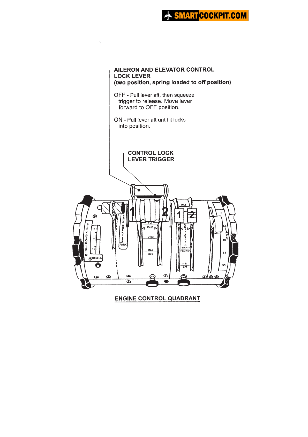
controls, and a flight control gust lock mechanism. All flight controls may be operated from
either the left or right pilots’ position.
Indications for flight control positions or malfunctions are provided by trim position indicators,
the powered flight control surface indicator and a series of caution lights.
Flight control surfaces location
Dash8-200/300 - Flight Controls
Page 9

Yaw control
Directional control about the yaw axis is provided by the rudder control system. The rudder is
hydraulically powered and controlled through displacement of either pilot’s rudder pedals. A
yaw damper operates through the rudder control system to improve directional stability.
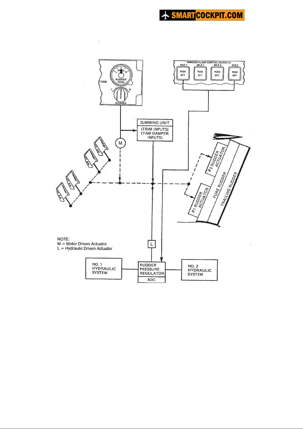
Rudder control system
The rudder has two sections (fore and trailing) driven by dual hydraulic actuators positioned
by either pilot’s rudder pedals.
The position of the rudder is shown on the PFCS indicator. Full-scale rudder deflection is
indicated by movement of the pointer to the index marks (16qleft marking, 18qright marking).
Rudder trim is provided by a two speed electric actuator, which has the capability to displace
the fore rudder 10º left or right of centre. Control of this actuator is by a spring-loaded rotary
switch on the TRIM panel to the rear of the aft electronics panel.
The fore rudder is hinged to the vertical stabilizer and is moved by both actuators. The
trailing rudder is hinged to the fore rudder and is geometrically geared to the vertical
stabilizer by push rods such that trailing rudder deflection is twice that of the fore rudder.
A pressure regulator controls hydraulic pressure to each rudder actuator. The regulator limits
actuator pressure to 1500 Psi at airspeeds below 150 KIAS and 900 Psi above 150 KIAS, in
response to speed signals from the air data computers (ADC’s), to reduce rudder sensitivity
at high speeds. Pressure switches, armed by ADC speed signals, are positioned in each
actuator's supply lines.
Maximum fore rudder travel is allowed only when the flap selector lever is out of the 0º
position to provide necessary authority at lower airspeeds. A mechanical rudder travel
restrictor limits rudder deflection to 12º with the flap selector lever at 0.
Yaw damper
A yaw damper system operates independently or in conjunction with the automatic flight
control system (AFCS) to provide compensating rudder inputs whenever the aircraft deviates
from coordinated flight. In level flight it acts to improve directional stability by damping
oscillation in yaw caused by turbulence. In turns initiated by the crew or the AFCS it provides
the necessary rudder deflection to maintain turn coordination.
Accelerometers within the flight guidance computer provide yaw data, which is combined
with other flight condition information. To provide output command signals to an electric yaw
damper actuator that can reposition the rudder up to 5º to left or right of an existing rudder
setting to maintain coordinated flight.
The yaw damper is engaged by means of an YD press-on/press-off switch light on the flight
guidance controller, located on the glareshield panel. Engaging the autopilot will
automatically switch on the yaw damper. The autopilot can not be engaged with the yaw
damper off.
Dash8-200/300 - Flight Controls
Page 10
Rudder control diagram
Dash8-200/300 - Flight Controls
Page 11

Rudder control diagram
Dash8-200/300 - Flight Controls
Page 12

Pitch control
The pitch control surfaces consist of two, spring tab assisted elevators.
Elevators
Pitch movement is controlled by two elevator surfaces, each having an independent control
system. The left elevator is controlled by fore and aft movement of the left pilot's control
column and the right elevator by fore and aft movement of the right pilot’s control column.
The control columns are mounted at each end of a torque tube below the flight compartment
floor, which normally joins the columns so that they move together. The torque tube
incorporates a latch mechanism, which permits the columns to be separated following a jam
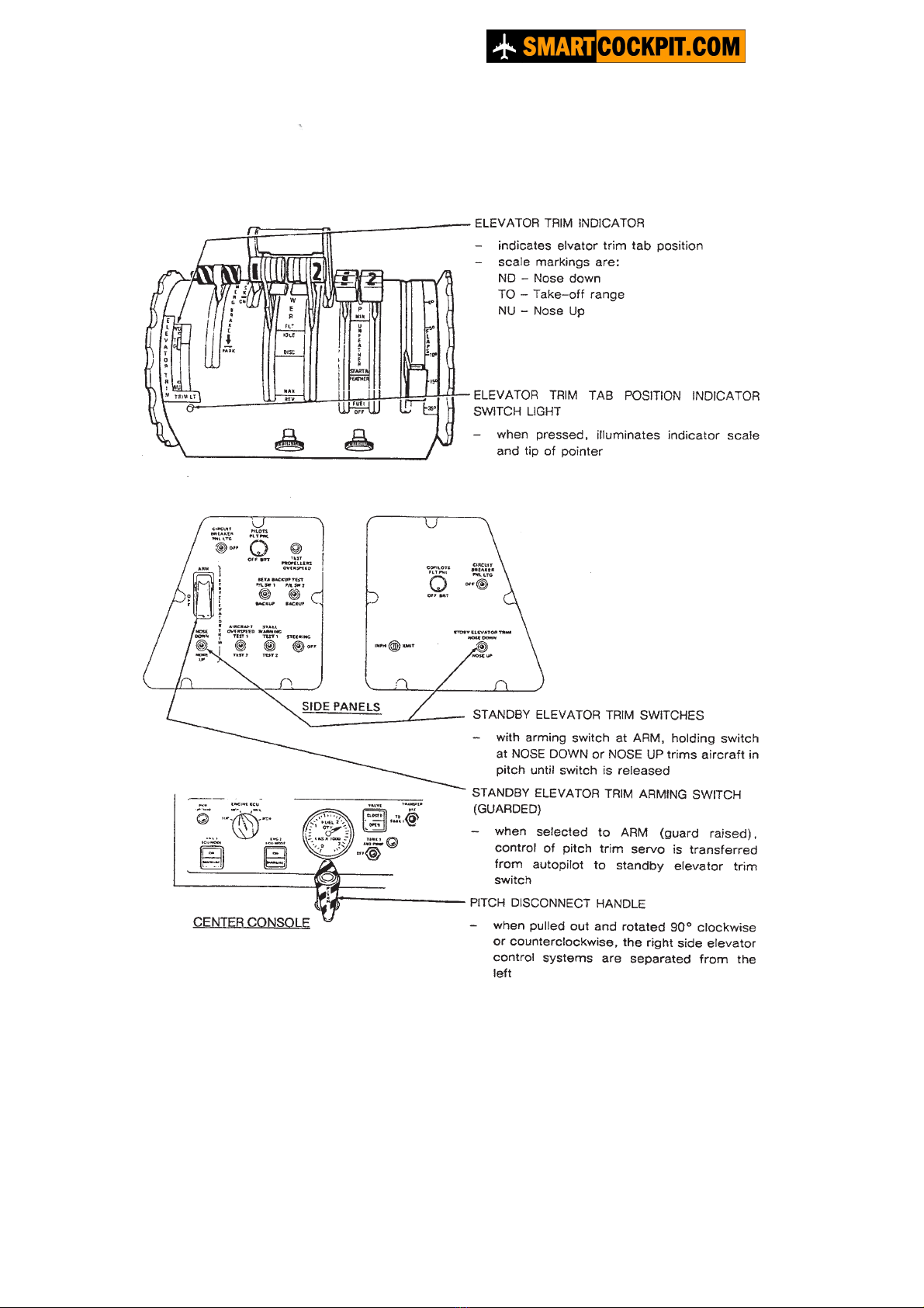
in either elevator system. A pitch disconnect handle located on the left side of the centre
console, marked PITCH DISC, releases the latch when pulled out following an elevator jam.
With the columns separated, the jammed side is isolated and pitch can be controlled with the
remaining elevator system.
Each elevator has a torsion spring mechanism, which drives the elevator surface in
conjunction with a spring tab on its inboard trailing edge. With elevator control input, this
provides a servo assist, which reduces elevator control forces.
Elevator trim is provided by tabs on each surface, outboard of the spring tabs. Two trim
wheels, mounted on a common shaft, are provided on each side of the power lever quadrant
on the centre console.
A trim position indicator is geared to the trim wheel shaft, consisting of a window and pointer
in the top of the power lever quadrant beside the pilot's trim wheel. A potentiometer within the
indicator sends trim position signals to the flight data recorder.
The standby trim system provides a means of trimming the aircraft following failure of the
manual trim system. A guarded standby elevator trim switch is located on the left pilot’s side
console panel. When selected from OFF to ARM it switches control of the trim servo from the
autopilot to an adjacent NOSE UP/NOSE DOWN switch. A duplicate NOSE UP/NOSE
DOWN switch is provided on the right pilot’s side console panel. Selection of either switch to
its spring-loaded NOSE UP or NOSE DOWN position activates the servo to trim the aircraft
in pitch. Arming the standby trim system immobilizes the normal elevator trim system.
Dash8-200/300 - Flight Controls
Page 13

Elevator control diagram
Dash8-200/300 - Flight Controls
Page 14

Roll control
Roll control is by conventional cable-operated ailerons, augmented by cable-operated,
hydraulically activated, roll spoilers. The rotational movement of the pilot's control wheel
activates the roll spoilers while the co-pilot’s control wheel activates the ailerons. An
interconnect linkage joins the pilot's and co-pilot’s control wheels so that both systems are
operated from either wheel. A clutch within the linkage can be disengaged manually, by
means of a roll disconnect handle on the flight compartment centre console, to separate the
left and right roll control circuits in the event of a jam in either circuit. With the control circuits
separated, control can be maintained with the un-jammed control wheel.
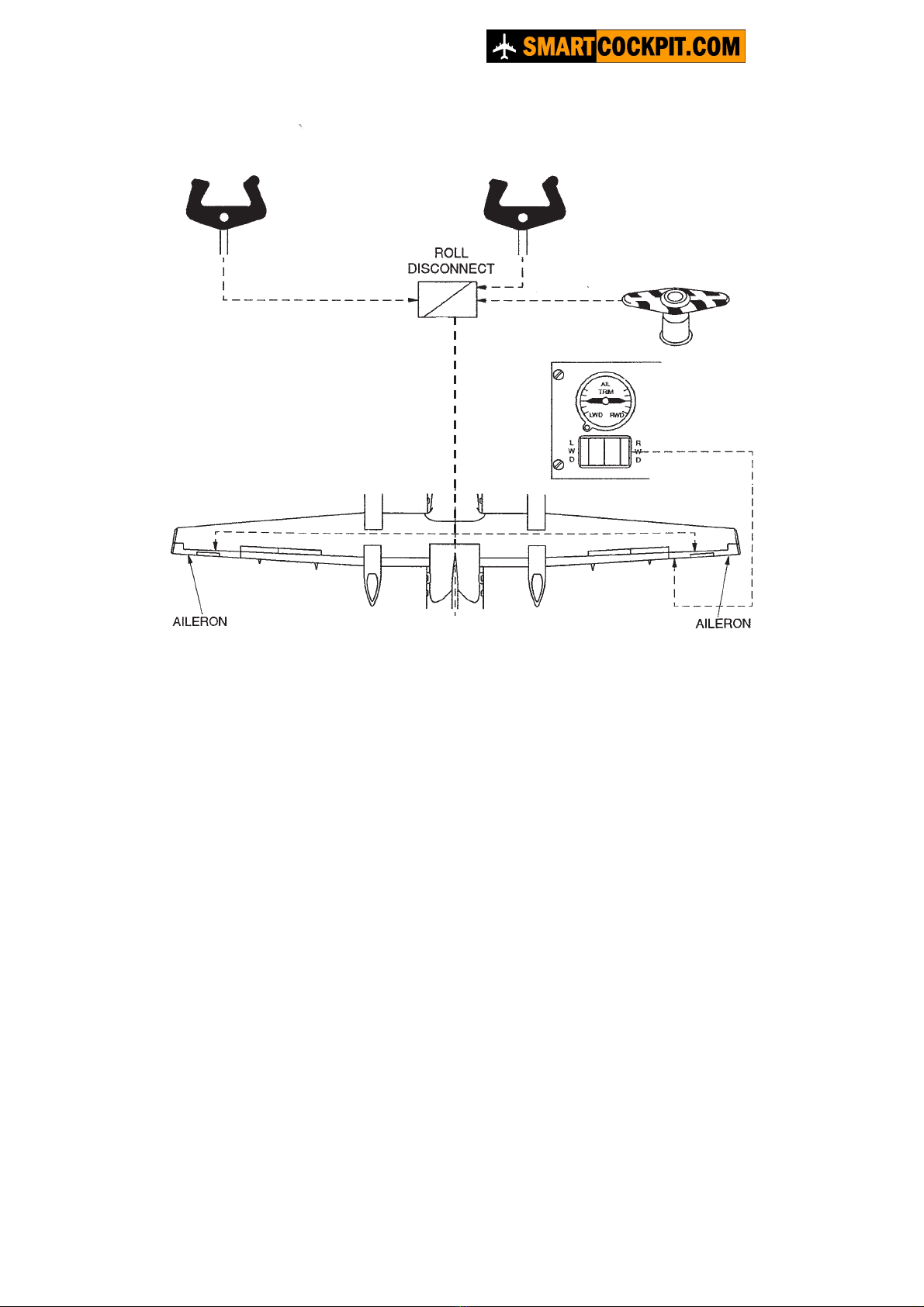
Ailerons
An aileron is located on each wing outboard of the flaps. Rotation of either control wheel
actuates the ailerons differentially by means of a cable control loop, with inter-connection to
applicable roll spoilers.
Geared tabs on the trailing edge of each aileron assist aileron deflection. The tabs are
geared to a static position, which is aerodynamically neutral relative to the aileron. When the
aileron is deflected, the geared tab moves in the opposite direction creating a localized lifting
force about the tab in the direction of aileron deflection, thus assisting aileron movement.
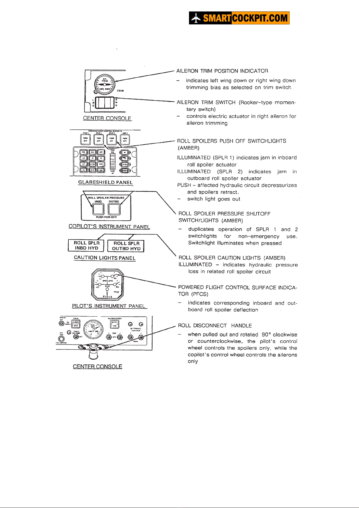
The right aileron trim tab, using an electric actuator built into the aileron, provides aileron
trim. A L/R AILERON rocker switch, located on the TRIM panel on the centre console
operates the actuator when depressed to the left or right. The actuator trims aileron control
pressure by biasing the static neutral position of the trim tab. An indicator adjacent to the L/R
AILERON rocker switch shows the degree of trim actuator displacement from neutral.
Dash8-200/300 - Flight Controls
Page 15
Aileron control diagram
Dash8-200/300 - Flight Controls
Page 16

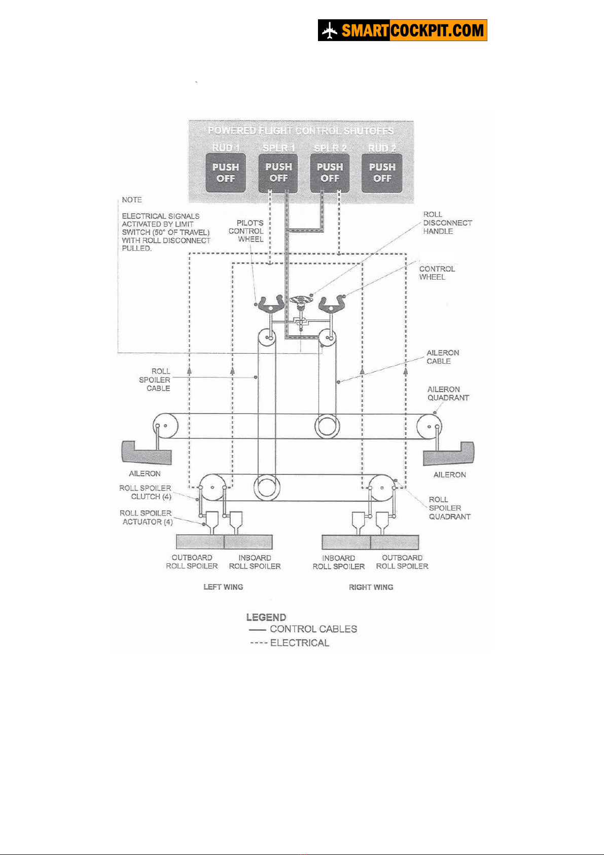
Roll Spoilers
The roll spoilers consist of four spoiler panels, two to a wing, positioned inboard of the
ailerons on the upper wing surfaces and driven by individual hydraulic actuators. The spoilers
respond differentially to control wheel movement by extending from the left or right wing in
proportion to associated upward displaced aileron. At airspeeds above 140 KIAS, the
outboard roll spoilers are disabled to reduce control sensitivity. Each actuator linkage is
connected so that in the event of a jam, overpowering force applied to the control wheel
disengages the linkage preventing the jam from immobilising the roll spoiler cable circuit.
A limit switch built into each mechanism illuminates one of the POWERED FLIGHT
CONTROL SHUTOFFS - SPLR switch lights (either SPLR 1 in the event of an inboard
actuator linkage jam or SPLR 2 for an outboard actuator linkage jam).
When pressed, each switch light disables the affected roll spoilers.
A roll spoiler cable circuit jam, necessitating operation of the ROLL DISC handle to control
the aircraft by ailerons alone, may result in partially extended roll spoilers if the jam occurred
during a roll input. The resulting counteracting aileron input necessary to control the aircraft
will illuminate both SPLR switch lights (via an under floor limit switch) if aileron travel
exceeds 50º of control wheel displacement from neutral. The switch lights must then be
immediately pressed to retract the spoilers and restore symmetrical aileron control.
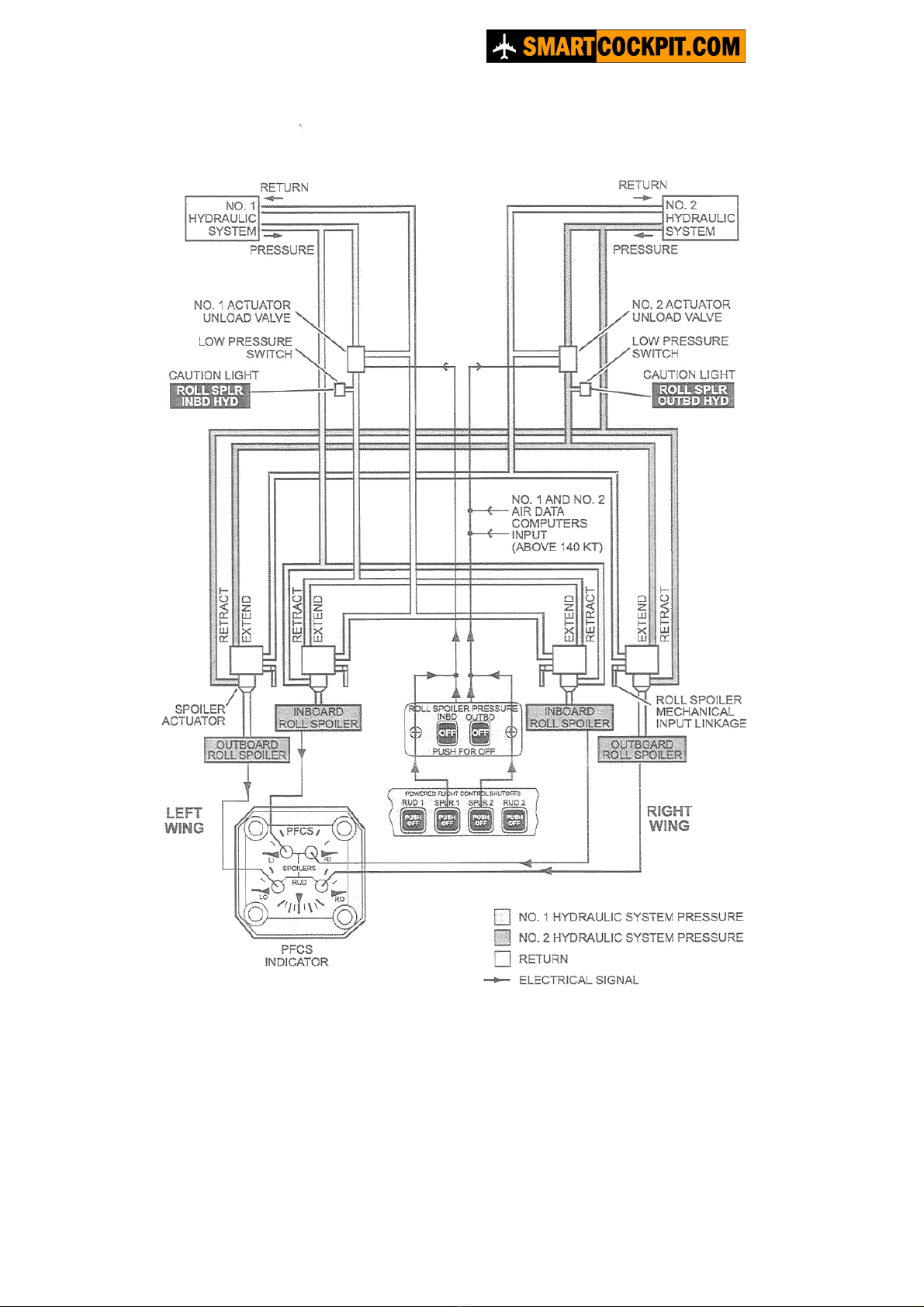
Two caution lights, marked ROLL SPLR INBD HYD and ROLL SPLR OUTBD HYD are
provided to warn that extension pressure to the affected actuators has been removed
following operation of the switch lights mentioned above or hydraulic system failure. The
OUTBD HYD light, however, does not illuminate when its system is depressurised by ADC
signals.
Spoiler motion and position is at all times directly proportional to control wheel movement.
The PFCS indicator in the flight compartment displays roll spoiler position in response to
position sensors at each roll spoiler panel.
Alternate roll spoiler pressure switches
Two roll spoiler switch lights labelled INBD and OUTBD provide an alternate method of de-
activating a roll spoiler during flight training. These switch lights perform the same function as
the SPLR 1 and SPLR 2 switch lights on the glareshield panel. However when INBD and/or
OUTBD switch light is/are pushed ROLL SPLR OUTBD HYD (all airspeeds) caution light(s)
SPLR 1 and SPLR 2 switch light remain active in the event a genuine roll control malfunction
occurs.
Dash8-200/300 - Flight Controls
Page 17

Roll spoiler control diagram
Dash8-200/300 - Flight Controls
Page 18
LEFT
RIGHT
PILOTS
’
S
Dash8-200/300 - Flight Controls
Page 19
Roll spoilers diagram
Dash8-200/300 - Flight Controls
Page 20
Other manuals for Dash8-200
1
This manual suits for next models
1
Other SmartCockpit Aircraft manuals

Popular Aircraft manuals by other brands

Gin Gliders
Gin Gliders Genie Lite 2 Series Pilot's manual

FLIGHT DESIGN
FLIGHT DESIGN CTSW-2006 quick start guide

LittleCloud
LittleCloud Goose manual

Wipaire
Wipaire Wipline 3730 Service manual and instructions

Nirvana Paramotors
Nirvana Paramotors KATANA user guide

Dancing Wings Hobby
Dancing Wings Hobby S22 instruction manual


