1
Protect yourself and others from injury— read, follow, and save these important safety
precautions and operating instructions.
I. Symbol Usage
DANGER! − Indicates a hazardous
situation which, if not avoided, will
result in death or serious injury. The
possible hazards are shown in the
adjoining symbols or explained in
the text.
Indicates a hazardous situation
which, if not avoided, could result in
death
or serious injury. The possible
hazards are shown in the adjoining
symbols or explained in the text.
NOTICE − Indicates statements not related to
personal injury.
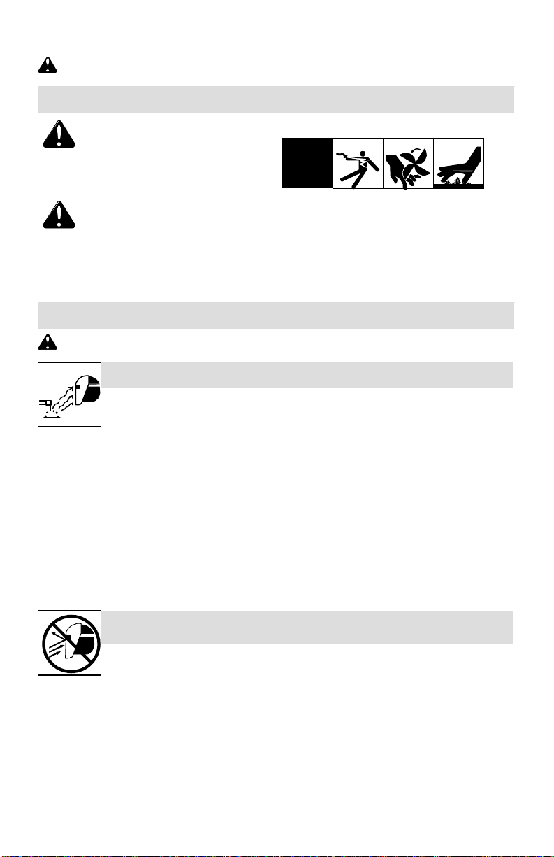
II. Arc Welding Hazards
Indicates special instructions.
This group of symbols means Warning!
Watch Out! ELECTRIC SHOCK,
MOVING PARTS, and HOT PARTS
hazards. Consult symbols and related
instructions below for necessary actions
to avoid the hazards.
Only qualified persons should install, operate, maintain, and repair this unit.
ARC RAYS can burn eyes and
skin.
Arc rays from the welding process produce intense visible and invisible (ultraviolet
and infrared) rays that can burn eyes and skin. Sparks fly off from the weld.
•Wear a welding helmet fitted with a proper shade of filter to protect your
face and eyes when welding or watching (see ANSI Z49.1 and Z87.1 listed
in Safety Standards). Refer to Lens Shade Selection on page 7.
•Wear approved safety glasses with side shields under your helmet.
•Use protective screens or barriers to protect others from flash, glare,
and sparks; warn others not to watch the arc.
•Wear protective clothing made from durable, flame-resistant material
(leather, heavy cotton, and wool) and foot protection.
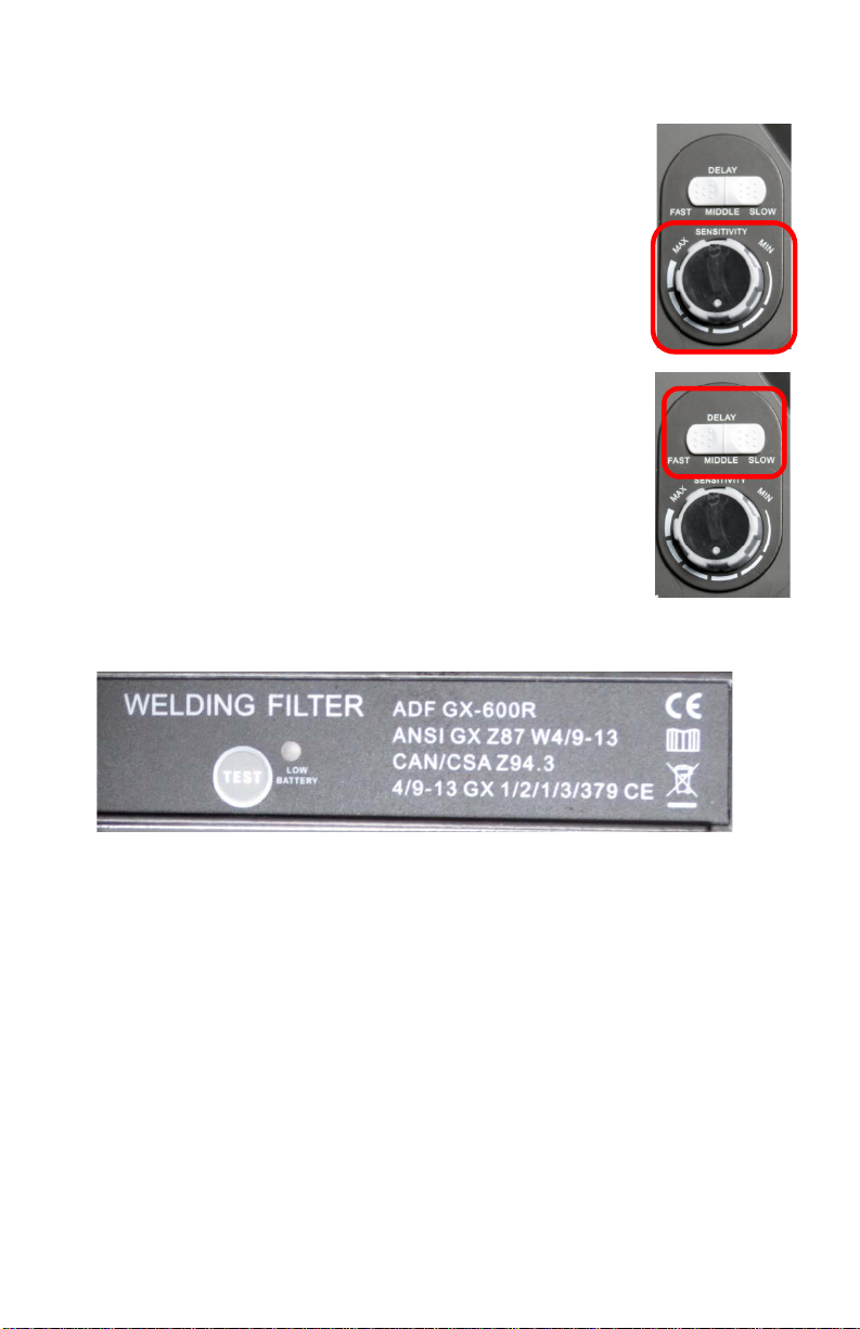
•Before welding, adjust the auto-darkening lens sensitivity setting to meet the
application.
•Stop welding immediately if the auto-darkening lens does not darken when the
arc is struck.
•See the Owner’s Manual for more information.
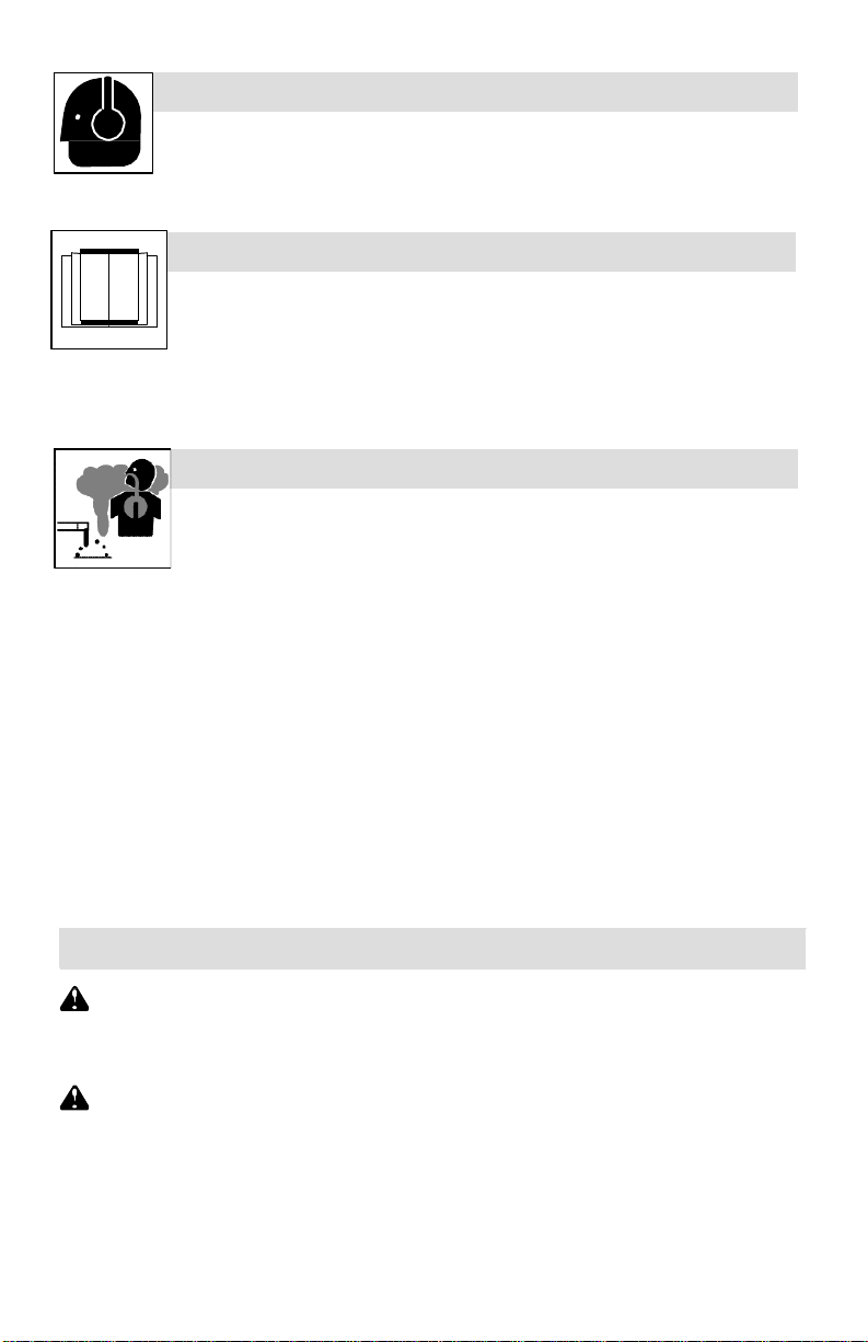
WELDING HELMETS do not provide unlimited eye, ear, and
face protection.
Arc rays from the welding process produce intense visible and invisible (ultraviolet
and infrared) rays that can burn eyes and skin. Sparks fly off from the weld.
•Use impact resistant safety spectacles or goggles and ear protection at all
times when using this welding helmet.
•Do not use this helmet while working with or around explosives or corrosive
liquids.
•Do not weld in the overhead position while using this helmet.
•Inspect the auto-lens frequently. Immediately replace any scratched,
cracked, or pitted cover lenses or auto-lenses.