SMARTfit Strike Target User manual

1
Congratulations on the purchase of your new
SMARTfit Strike Target system!
Please follow the set-up instructions below for the Secure Case and/or Duffel Case.
If you need assistance, feel free to give our Customer Service a call at
1-800-900-8542 x 116, between the hours of 9:00 a.m. and 4:30 p.m. PST,
Monday thru Friday or watch our easy to follow instruction video on our website at
https://smartfitinc.com/smart-installation-instructions/

2
Strike Target Instruction Manual Contents
Strike Target Instruction Manual Contents......................................................................2
Getting Started with your Strike Target System...............................................................3
Pod Battery Installation ...................................................................................................3
CPU Battery Installation ..................................................................................................8
Attaching the CPU to the Duffle Bag Stand...................................................................10
Pod Layout....................................................................................................................11
Rack Straps...................................................................................................................13
Concrete Wall Installation..............................................................................................15
Stud Wall Installation.....................................................................................................17
Pod Stand Assembly.....................................................................................................19
Using the SMARTfit App................................................................................................22
Download the SMARTfit App .....................................................................................22
Open and Closed Platforms.......................................................................................27
Play a Free Activity....................................................................................................29
Play a Free Program..................................................................................................31
Create an Activity.......................................................................................................33
Create a Program ......................................................................................................37

3
Getting Started with your Strike Target System
1. Examine the Enclosed Inventory Checklist List
2. Carefully lay the closed Duffle Case or Secure Case on the
floor.
3. Unzip the large pocket on the Duffel Case or open the
clasps of the Secure Case.
Pod Battery Installation
1. Remove the
SMARTfit batteries
and Charging
Station from the
Package.
2. Insert the Clear
Plastic Battery
Dividers into the
slots of the Main
Central Power
Station.

4
3. Insert the SMARTfit
Batteries in between
each plastic divider.
4. Connect the
SMARTfit batteries
to the Charging
Station using the
USB Wires
provided.
5. Connect the Power
Cord to the Power
Station. Allow to
charge overnight
6. (A minimum of 7
hours, but not
longer than 24
hours).
7. After charging is
complete, pair up
each of the 5
batteries with each
of the 5 Pods. The
6th battery will be
used for the CPU.

5
8. Locate the battery
compartment on
the side of each
Pod.
9. Slide open the
battery
compartment on
the side of each
Pod by applying
pressure and
sliding in upward
motion. (Use a
finger at the bottom
and one finger on
top for easier
movement).
10.Locate the ON/OFF
button on the
SMARTfit battery.
Turn it on by
pressing the
ON/OFF button
twice. A bright white
light will indicate that
the battery is on.
11. Insert the
SMARTfit battery
with one hand,
while holding the
USB target wire
with the other
hand.

6
12. Make sure that the
2.1A USB port,
closest to the light,
is closest to the
USB wire inside of
the battery
compartment.
13. Plug the USB wire
into the 2.1A USB
port before placing
the battery all the
way inside the Pod
compartment.
14. Locate the Pod’s
rectangular ON/OFF
Button positioned at
the opening of the
battery compartment
and press it to turn it
on.
15. Slide the battery
compartment cover
back on for
securing the
battery.
16. If the Strike Pods
are ever
disconnected from
the CPU, the
display will turn off
after 5 minutes.
17. Show-mode is a
feature that
permanently keeps
the Strike Pod

7
display turned on.
To activate Show-
mode, hold the
on/off button until
the target displays
“OFF” in capital
letters. The Strike
Pod display will
remain active until
the battery life runs
out.

8
CPU Battery Installation
1. Locate the battery compartment on
top of the CPU.
2. Slide open the CPU’s battery
compartment by applying pressure
and sliding in a downward motion.
3. Locate the ON/OFF button on the
SMARTfit battery. Turn it on by
pressing the ON/OFF button twice.
A bright white light will indicate that
the battery is on.
4. Insert the SMARTfit battery with
one hand, while holding the USB
target wire with the other hand.
Make sure that the 2.1A USB port
(CLOSEST TO THE LIGHT) is
closest to the USB wire inside of
the battery compartment. Plug the
USB wire into the 2.1A USB port
before placing the battery all the
way inside the Pod compartment.
5. Place the battery cover back on to
secure the battery.

9
6. The CPU’s lights will turn on and
display your 8-digit User ID.

10
Attaching the CPU to the Duffle Bag Stand
1. Lay the CPU face down on a flat
surface (the top of the DuffleCase
can be used).
2. Stand the Duffle Case in the
upright position. Extend the Duffle
Case’s handle upwards.
3. Attach the included CPU strap to
the CPU by placing the 2 CPU Strap
Pins into the 2 Pinholes located on
the top back portion of the CPU.
4. Use the CPU strap, which you
attached to the CPU in step 3, to
secure the CPU on the Duffle Case
handle.

11
Pod Layout Set up your pods in one of the following layouts (floor, rack, wall):
1. Pods can be laid out in any
configuration on the floor. No
more than 100’ from the CPU.
2. Pods can be fastened to a rack
in a gym using any of the vertical
rack columns.
3. Or on a wall using the provided
template with markings for the
Controller (optional) and the
pods to place provided wall
screws in various configurations:
a. In a vertical line
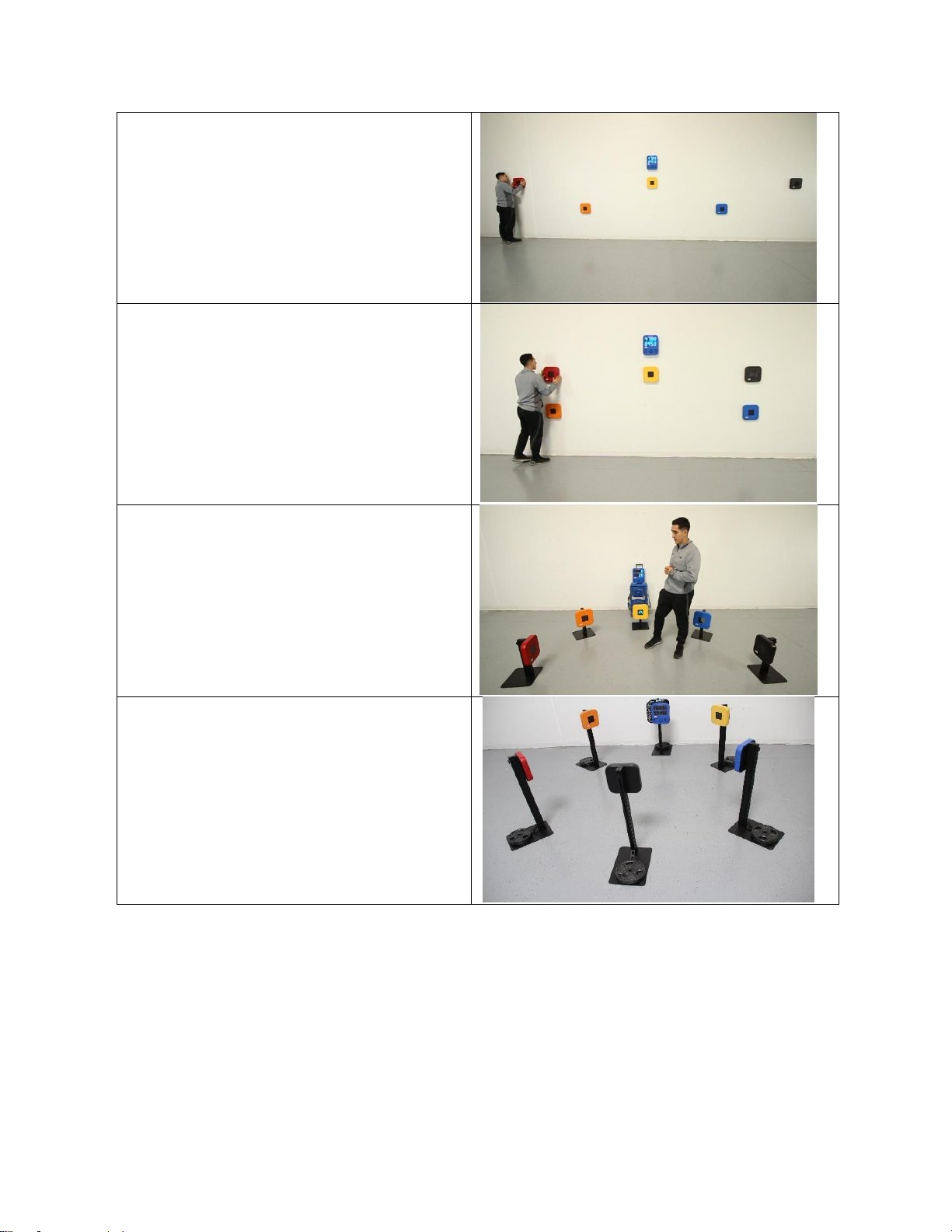
12
b. Wide placement for
Cardio and lateral
movement.
c. Two stacked on either
side of the controller.
4. Using SMARTfit 36” pod stands
5. Using SMARTfit 68” pod stands

13
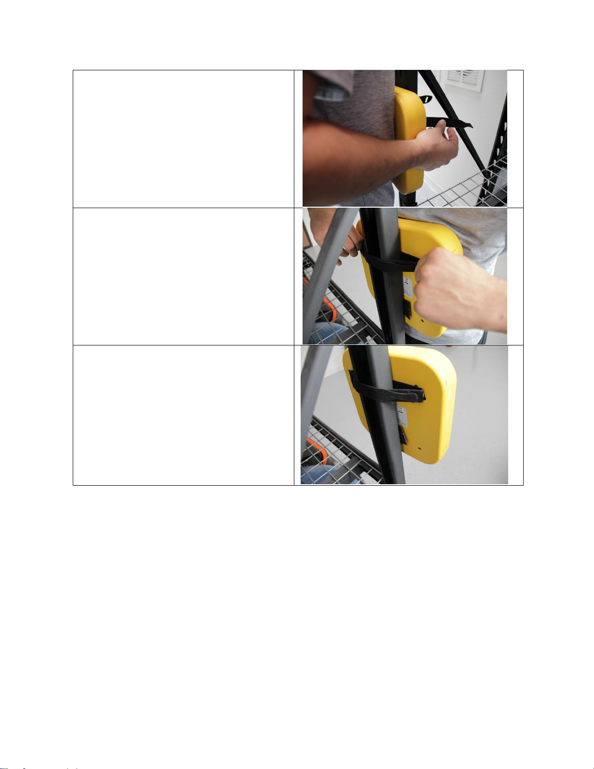
Rack Straps
1. Locate one of the rack straps
located in the duffle case.
2. Secure one end of the strap to
one of the pods.
3. Secure the second end of the
strap.
4. Attach the Pod onto the gym rack.
14
5. Press body against the front of
the pod, so that you can use both
hands to secure the rack strap.
6. Slide one end of the rack strap
through the opposite end, then
tightly secure the strap.
7. Make sure the rack strap is tight
enough, so that the Pod can
stand on its own.

15
Concrete Wall Installation
1. Locate the Pod template in the
case.
2. Place it against the wall, while
making sure it’s level.
3. Mark all 3 holes labeled “SP.”
4. Mark all 3 “SP” holes in four more
locations.
5. Mark a set of 3 holes labeled
“CPU.”
6. Using a power drill and ¼’’
concrete drill bit, drill 1 ½” deep
holes at each of the marked “SP”
and “CPU” holes. There should be
a total of 18 drill holes
7. Use the Plastic tool kit labeled
“Brick Wall.”

16
8. Remove the blue anchors, place
them in each of the drill holes.
9. Using a rubber mallet hammer the
anchors into the wall.
10.Using a Phillips screwdriver, loosen
the anchor screw about ½”.
11.Screw in the blue screws to each of
the 18 anchors.
12.Now attach all 5 Pod and CPU to
their desired location. (Refer to
images below).

17
Stud Wall Installation
1. Locate the Pod template in the
case.
2. Place it against the wall, while
making sure it’s level.
3. Mark all 3 holes labeled “SP.”
4. Mark all 3 “SP” holes in four more
locations.
5. Mark a set of 3 holes labeled
“CPU.”
6. Using a power drill and 5/16’’ drill
bit, drill 2 ½” deep holes at each of
the marked “SP” and “CPU” holes.
There should be a total of 18 drill
holes.
7. Use the Plastic tool kit labeled
“Stud Wall.”

18
8. Remove the Stud Wall anchors,
place them in each of the drill holes.
9. Using a rubber mallet hammer the
anchors into the wall.
10.Using a Phillips Screw Driver,
loosen the anchor screw about 1/2’’
11.Attach all 5 Pod and CPU to their
desired location.
19
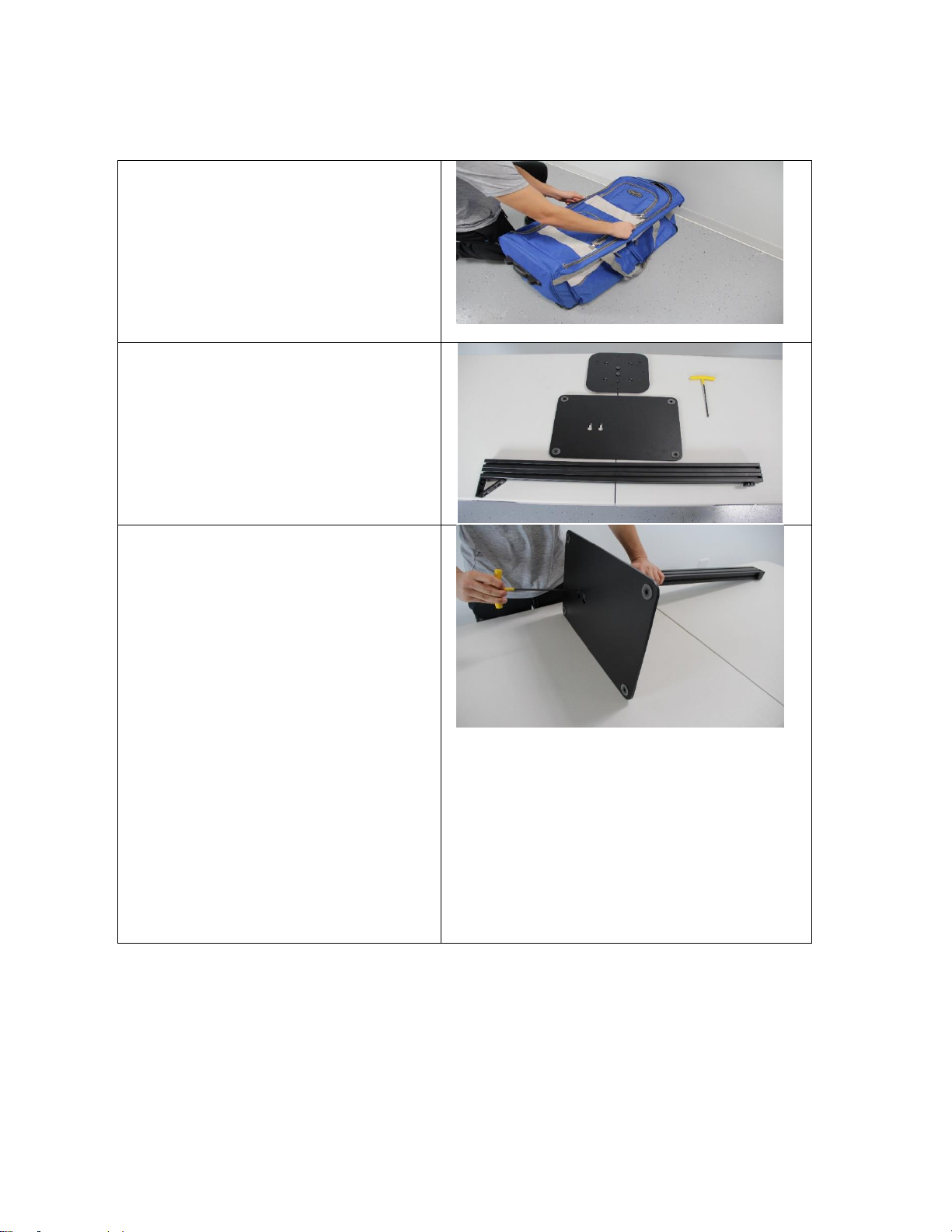
Pod Stand Assembly
1. Carefully lay the case on the
floor.
2. Unzip the large pocket and
remove all of the pieces. Lay it
on the floor.
3. Set aside 1 base, 1 pole
extension, and 1 backplate.
4. Locate the T-Handle Hex
Wrench inside the case.
5. Gather the base and pole
extension.
6. Place the pole extension with
the triangle/screws facing the
long part of the plate.
7. Slide the screws, at the bottom
of the pole extension, into the
base.
8. Lock it by sliding the screws in
a lateral direction.
9. Using the T-handle Hex
Wrench, tighten the screws to
the base.

20
10.Place the stand into the upright
position.
11.Before attaching the back plate,
take off the cover piece located
at the top of the pole extension.
12.The slider on the back plate will
slide into the pole extension.
13.Slide down the back plate to a
convenient height.
14.Using the T Handle Hex
Wrench, tighten the two middle
screws to lock the backplate in
place.
15.Re-attach the front cover cap.
(only used on 68” high stands)
16.Loosen/Tighten the knob on the
back of the pole extension to
adjust the height.
Table of contents
Other SMARTfit Fitness Equipment manuals


