SMARTfit 1-30303 User manual

0
SMARTfit Strike Pod User Manual
Version 11.7
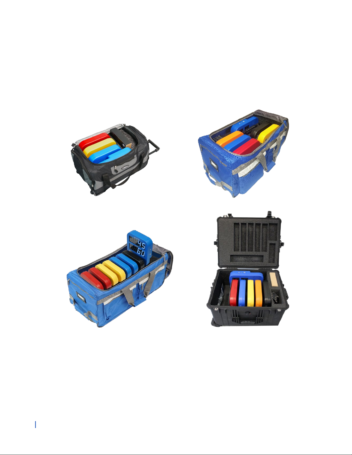
3 Strike Pod System – w/ Portable Stands………... 1-30303
5 Strike Pod System w/Rolling Duffel……..……….. 1-30302
7 Strike Pod System w/Rolling Duffel………..…….. 1-30304
5 Strike Pod System w/Secure Case……………….. 1-30300
1-800-900-8542
www.smartfitinc.com

1 ©SMARTfit Inc. All Rights Reserved.
Table of Contents
Important Safety Instructions ...................................................................................... 2
Maintenance................................................................................................................... 3
Battery Operations ........................................................................................................ 3
Getting Started with your Strike Target System ......................................................... 4
Pod Battery Installation ................................................................................................ 5
CPU Battery Installation.............................................................................................. 10
Pod Layout................................................................................................................... 12
Rack Straps.................................................................................................................. 14
Concrete Wall Installation........................................................................................... 17
Stud Wall Installation .................................................................................................. 19
Pod Stand Assembly................................................................................................... 21
Controller Settings ...................................................................................................... 25
Downloading the SMARTfit App and Creating a New Account on the SMARTfit
Cloud ............................................................................................................................ 27
Register Your Controller............................................................................................. 35
Four Icons on the Sign-On Page................................................................................ 38
Choosing Between a Local and Cloud Account ....................................................... 40
Modes and License Keys............................................................................................ 42
Trainer Requests & Client Accepts............................................................................ 44
Start a Game ................................................................................................................ 47
Standard Settings........................................................................................................ 49
Pre-designed Activities............................................................................................... 54
Pre-designed Programs.............................................................................................. 57
Create an Activity........................................................................................................ 59
Create a Program ........................................................................................................ 64
Search and Export Data.............................................................................................. 73
Identification of Radio Equipment:
......................................................................... 80
Object of the declaration:
......................................................................................... 80
The object of the declaration described above is in conformity with the
relevant Union harmonization legislation:
............................................................. 80
RF Frequencies and Power Input............................................................................... 82

2 ©SMARTfit Inc. All Rights Reserved.
IMPORTANT SAFETY INSTRUCTIONS
(READ ALL INSTRUCTIONS)
CAUTIONS, WARNINGS and DANGERS
•This is not a toy and is intended for use by or under the supervision of adults.
•To reduce the risk of fire, replace only with a fuse of the same type and electrical rating.
•“No” user serviceable parts with the exception of the fuse.
•Please note the yellow CAUTION and WARNING labels on the device.
•Note all pinch points on the device before using.
•If an extension cord is used pay close attention to the current requirement and routing
to eliminate tripping hazards.
•Pay close attention to the pinch points pointed out in yellow CAUTION labels.
•Do not climb on the device.
•Weights in the back of the unit are required for safety.
•This appliance is not intended for use by persons (including children) with reduced
physical, sensory or mental capabilities, or lack of experience and knowledge, unless
they have been given supervision or instruction concerning use of the appliance by a
person responsible for their safety.
•Children should be supervised to ensure that they do not play with the appliance.
•PLEASE SAVE THESE INSTRUCTIONS

3 ©SMARTfit Inc. All Rights Reserved.
Maintenance
•Clean all surfaces with a water-based disinfectant, such as Windex Disinfectant.
•Check all bolts and ensure they are tightened.
•Check all mechanical parts for wear.
•Check wiring for wear and fraying.
Battery Operations
Power Banks are found in certain configurations of SMARTfit systems. This section only applies
to such systems.
•Only a power bank from SMARTfit Inc. may be used.
•Power banks must be removed from the system prior to charging the pack.
•Exhausted power banks must be disposed of properly in accordance with your local
laws.
•If the system is to be dormant for an extensive period remove all power banks.
4 ©SMARTfit Inc. All Rights Reserved.
Getting Started with your Strike Target System
1. Examine the Enclosed Inventory Checklist List
2. Carefully lay the closed Duffle Case or Secure Case on the floor.
3. Unzip the large pocket on the Duffel Case or open the clasps of the Secure Case.
This manual suits for next models
3
Table of contents
Other SMARTfit Fitness Equipment manuals


Popular Fitness Equipment manuals by other brands


G-FITNESS
G-FITNESS AIR ROWER user manual

CAPITAL SPORTS
CAPITAL SPORTS Dominate Edition 10028796 manual

Martin System
Martin System TT4FK user guide

CIRCLE FITNESS
CIRCLE FITNESS E7 owner's manual

G-FITNESS
G-FITNESS TZ-6017 user manual

Accelerated Care Plus
Accelerated Care Plus OMNISTIM FX2 CYCLE/WALK user manual


