SMARTfit PowerForce User manual

PowerForce –User Manual
Radlabor GmbH | Heinrich-von-Stephan-Str. 5c | 79100 Freiburg | Germany
www.smartfit.bike | www.radlabor.de
PowerForce
System
User manual
-
wireless edition

PowerForce –User Manual
Radlabor GmbH | Heinrich-von-Stephan-Str. 5c | 79100 Freiburg | Germany
www.smartfit.bike | www.radlabor.de
Inhalt
Important warnings................................................................................................................................... 3
1. Introduction ........................................................................................................................................... 4
1.1 Pedal forces .................................................................................................................................... 4
1.2 Force components.......................................................................................................................... 5
Fr (resultant / total –force).............................................................................................................. 5
Fe (effective / tangential –force) .................................................................................................... 5
Fu (unused / radial –force).............................................................................................................. 5
1.3 Measuring Principle ........................................................................................................................ 6
1.4 Technical Data –Wireless edition ................................................................................................. 7
2. After unpacking..................................................................................................................................... 8
2.1 components .................................................................................................................................... 8
2.2 Mounting.......................................................................................................................................... 9
3. Software Installation........................................................................................................................... 12
3.1 Install NI-DAQmx Driver................................................................................................................ 12
3.2 Install NI LabVIEW 2009 Runtime Engine Library....................................................................... 12
3.3 Install IMAGO Records®............................................................................................................... 12
4. IMAGO Record®.................................................................................................................................. 13
4.1 Introduction ................................................................................................................................... 13
4.2 First start and setup...................................................................................................................... 13
4.2.1 Load Setup-files ..................................................................................................................... 14
4.2.2 Set, save and load calibration values ................................................................................... 15
4.3 Description of IMAGO®................................................................................................................ 17
4.3.1 Main Menu.............................................................................................................................. 17
4.3.2 Index Tab ................................................................................................................................ 18
4.4 Measurement ................................................................................................................................ 21
5. CyclePlotAssistent.............................................................................................................................. 22
5.1 Quick buttons and contents ......................................................................................................... 24
5.2 Charts and Design......................................................................................................................... 25
5.3 Graph Selection............................................................................................................................. 26
5.4 Caption and legend....................................................................................................................... 27
5.5 Save quick button.......................................................................................................................... 28

PowerForce –User Manual
Radlabor GmbH | Heinrich-von-Stephan-Str. 5c | 79100 Freiburg | Germany
www.smartfit.bike | www.radlabor.de
Important warnings
Please read the following warnings, before beginning to use your PowerForce System. Otherwise,
your PowerForce could be damaged, or not function properly.
✓Do not over tight the pedals in the PowerForce System. Give some grease to the
connective sites to improve the reassembling of the pedals.
✓If your open a sensor, the transmitter unit or the connection box, the warranty is no
longer valid.
✓Never clean the sensor or the transmitter unit with water or use it in wet conditions.
✓Do not cramp the position switch –it is sensitive for pressure.
✓Check before each ride, that the sensors and the pedals are fixed properly.
✓When unplugging any connection, always pull straight down rather than sideways,
or you could damage connector pins. Never pull on the cable itself, but rather the
plug.
✓Carefully read through the full installation instructions before beginning, as
mounting the PowerForce System incorrectly can cause a fall or damage the
system.
✓Do not load the sensor with loads higher than 300kg.

PowerForce –User Manual
Radlabor GmbH | Heinrich-von-Stephan-Str. 5c | 79100 Freiburg | Germany
www.smartfit.bike | www.radlabor.de
1. Introduction
1.1 Pedal forces
In cycling the transfer of metabolic energy into physical power or velocity of the rider-bike-system is
not one-to-one. Environmental as well as mechanical and biomechanical factors affect cycling
performance. The propulsion of the bike is generated by pedal forces. Therefore, the determination
of pedal forces is a major prerequisite to analyze cycling performance capability from a
biomechanical point of view.
The question is not why to measure pedal forces but how to do it. Comparing other existing
instruments whose purpose is the determination of divers mechanical parameters concerning
cycling propulsion, there are some methodological or practical limitations regarding the
requirements of either a biomechanical lab or a sports related center.
The most important advantage of the PowerForce System is the fact that there is no restriction to a
certain pedal system. Cyclists do not have to change their pedal-shoe interface (cleats) if they want
to measure their pedal forces with the PowerForce.
PowerForce –User Manual
Radlabor GmbH | Heinrich-von-Stephan-Str. 5c | 79100 Freiburg | Germany
www.smartfit.bike | www.radlabor.de
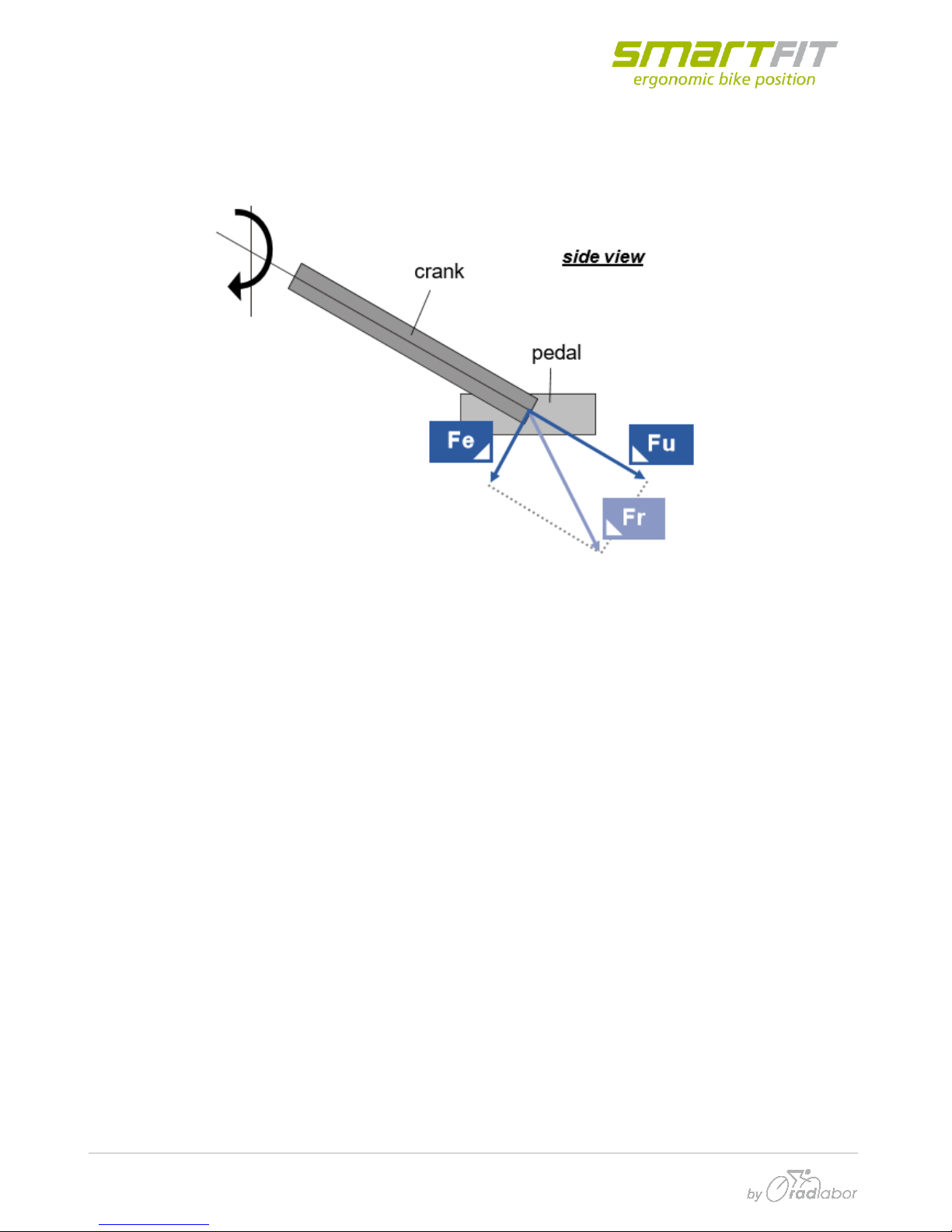
1.2 Force components
The PowerForce records the forces, which are performed on the pedal axis, separately for each leg.
Three force components (Fe, Fu und Fr) have to be differentiated.
Fr (resultant / total –force)
This is the total force which is generated by the athlete on the pedal. It is the vectorially sum of Fe
and Fu an is calculated, not measured.
Fr tells us about the total load, the rider applies to the system –the bike as well as to his own body.
Joint moments and forces result from (or cause) this component. Thus, e.g. inverse dynamics are
based on Fr.
Fe (effective / tangential –force)
Fe is the component of Fr which lies in moving direction of the crank/pedal which is a circle.
Therefore, the vector of Fe is always tangential to this circle or perpendicular to the crank. Fe is
responsible for the propulsion, but only if it is aligned forward with the rotating direction. If it is
aligned backward, e.g. if a rider does not pull up the pedal in the upstroke phase, Fe of the one side
must be subtracted from the other side.
Fu (unused / radial –force)
Fu is the component of Fr which does not generate any propulsion. It results in very small
deformation of the crank and pedal-axis. The direction off this force component is lengthwise to the
crank. The highest values appear around the bottom dead center (180° crank angle) where the
weight component (induces by the mass of the leg) adds to the muscular component.
Table of contents
Other SMARTfit Fitness Equipment manuals


Popular Fitness Equipment manuals by other brands


G-FITNESS
G-FITNESS AIR ROWER user manual

CAPITAL SPORTS
CAPITAL SPORTS Dominate Edition 10028796 manual

Martin System
Martin System TT4FK user guide

CIRCLE FITNESS
CIRCLE FITNESS E7 owner's manual

G-FITNESS
G-FITNESS TZ-6017 user manual

Accelerated Care Plus
Accelerated Care Plus OMNISTIM FX2 CYCLE/WALK user manual


