Topac HFW0220DVD User manual

MODEL: HFW0220DVD
BATTERY CHARGER
OPERATOR'S MANUAL
Please save these instructions. This manual contains important safety and operating
instructions. Read all instructions and follow them with each use of this product.
CONTENTS
IMPORTANT SAFETY INSTRUCTIONS ……………...………………………………. 1
PERSONAL SAFETY PRECAUTIONS ……………...………………………………. 2
2.………………………………...……………LENAPLORTNOC
OPERATING INSTRUCTIONS ……………...………………………………. 3
TROUBLESHOOTING FAULT CODES ……………………...………………………. 7
MAINTANANCE INSTRUCTIONS ……………...………………………………. 6
6.………………………………...……………ATADLACINHCET
IMPORTANT SAFETY INSTRUCTIONS
1. SAVE THESE INSTRUCTIONS. This manual contains important safety and operating
instructions. You may need to refer to these instructions at a later date.
2. CAUTION. To reduce risk of injury, charge only wet cell, lead-acid, automotive type
rechargeable batteries. Other types of batteries may burst causing personal injury and
property damage.
3. Do not expose charger to rain or snow.
4. Use of an attachment not recommended or sold by the battery charger manufacturer may
result in a risk of fire, electric shock, or injury to persons.
5. To reduce risk of damage to electric plug and cord, pull plug rather than cord when
disconnecting charger.
6. Make sure cord is located so that it will not be stepped on, tripped over, or otherwise
subjected to damage or stress.
7. An extension cord should not be used unless absolutely necessary. Use of improper
extension cord could result in a risk of fire and electric shock. If an extension cord must be
used, make sure:
a. That pins on plug of extension cord are the same number, size, and shape as those of
plug on charger;
b. That extension cord is properly wired and in good electrical condition;
c. If the length of the extension cord is less than 15 meter, use a 0.75mm2cord, If 30 meter -
1mm2, 60 meter -1.5mm2.
8. Do not operate charger with damaged cord or plug, replace the cord or plug immediately.
9. Do not operate charger if it has received a sharp blow, been dropped, or otherwise
damaged in any way; take it to a qualified serviceman.
10.Do not disassemble charger; take it to a qualified serviceman when service or repair is
required. Incorrect reassembly may result in a risk of electric shock or fire.
11.To reduce risk of electric shock, unplug charger from outlet before attempting any
maintenance or cleaning. Turning off controls will not reduce this risk.
12. WARNING - RISK OF EXPLOSIVE GASES
a. WORKING IN VICINITY OF A LEAD-ACID BATTERY IS DANGEROUS. BATTERIES
GENERATE EXPLOSIVE GASES DURING NORMAL BATTERY OPERATION. FOR THIS
REASON IT IS OF UTMOST IMPORTANCE TO READ THIS MANUAL AND FOLLOW THE
www.topacdc.com Amazon Store Facebook
1
HFW0220DVD
Micro Processor Technology
210 20
2/10/2012/24
READ WARNING ON BACK & INSTRUCTION MANUAL BEFORE USING
INSTRUCTIONS EXACTLY EACH TIME BEFORE USING CHARGER.
b. To reduce risk of battery explosion, follow these instructions and those published by
battery manufacturer and manufacturer of any equipment you intend to use in vicinity of
battery. Review cautionary marking on these products and on engine.
PERSONAL SAFETY PRECAUTIONS
1. Someone should be within range of your voice or close enough to come to your aid when
you work near a lead-acid battery.
2. Have plenty of fresh water and soap nearby in case battery acid contacts skin, clothing, or
eyes.
3. Wear complete eye protection, and clothing protection. Avoid touching eyes while working
near battery.
4. If battery acid contacts skin or clothing, wash immediately with soap and water. If acid
enter eyes, immediately flood eyes with running cold water for at least 10 minutes and get
medical attention immediately.
5. NEVER smoke or allow a spark or flame in vicinity of battery or engine.
6Be extra cautious to reduce risk of dropping a metal tool onto battery. It might spark or
short circuit battery or other electrical part that may cause explosion.
7. Remove personal metal items such as rings, bracelets, necklaces, and watches when
working with a lead-acid battery. A lead-acid battery can produce a short circuit current high
enough to weld a ring or the like to metal, causing a severe burn.
8. Use the charger for charging a LEAD-ACID battery only. It is not intended to supply power
to a low-voltage electrical system other than in a starter motor application. Do not use battery
charger for charging dry-cell batteries that are commonly used with home appliances. These
batteries may burst and cause injury to persons and damage to property.
9. NEVER charge a frozen battery.
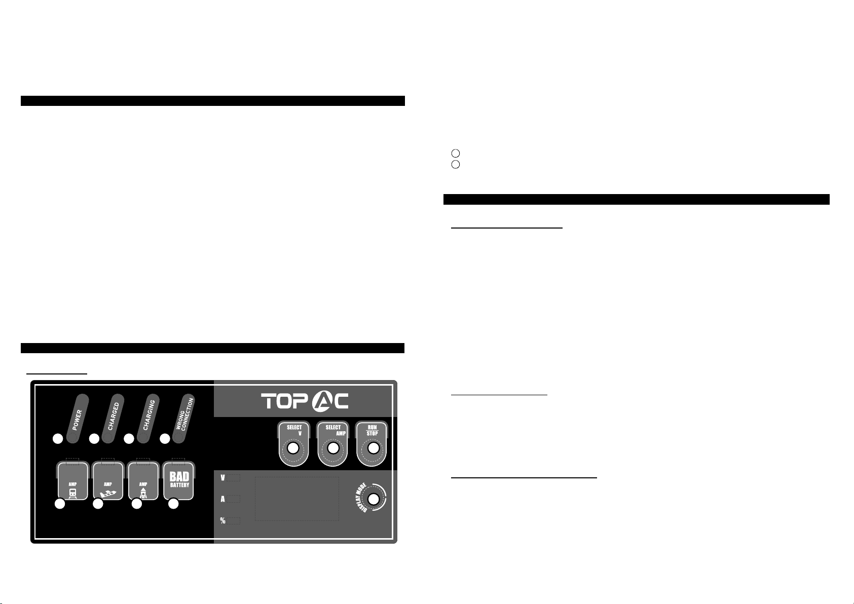
CONTROL PANEL
LED DISPLAY
OPERATING INSTRUCTRIONS
PREPARING TO CHARGE
a. If necessary to remove battery from vehicle to charge, always remove the grounded
terminal from battery first. Make sure all accessories in the vehicle are off, so as not to cause
an arc.
b. Be sure area around battery is well ventilated while battery is being charged. Gas can be
forcefully blown away by using a piece of cardboard or other non-metallic material as a fan.
c. Clean battery terminals. Be careful to keep corrosion from coming in contact with eyes.
d. Add distilled water in each cell until battery acid reaches level specified by battery
manufacturer. This helps purge excessive gas from cells. Do not overfill. For a battery
without cell caps, carefully follow manufacturer's recharging instructions.
e. Study all the battery manufacturer's specific precautions such as removing or not
removing cell caps while charging and recommended rates of charge.
f. Determine voltage of battery by referring to car owner's manual and make sure that output
voltage is set at correct voltage. If charger has adjustable charge rate, charge battery initially
at lowest rate.
CHARGER LOCATION
a. Locate charger as far away from battery as output cables permit.
b. Never place charger directly above battery being charged; gases from battery will corrode
and damage charger.
c. Never allow battery acid to drip on charger when reading gravity or filling battery,
d. Do not operate charger in a closed-in area, or restrict ventilation in any way.
e. Do not set a battery on top of charger.
DC CONNECTION PRECAUTIONS
a. Connect and disconnect DC output clamps only after setting any charger switches to off
position and removing AC cord from electric outlet. Never allow clamps to touch each other.
b. Attach clamps to battery posts and twist or rock back and forth several times to make a
good connection. This tends to keep the clamps from slipping off terminals and helps to
reduce risk of sparking.
1
8 9 10 11 12
2 3 4
5 6 7
2 3
①Power Indicator LED
② Charged Indicator LED
③Charging Indicator LED
④Wrong Connection Indicator LED
⑤SELECT VOLTAGE switch with the following selections: 12V and 24V
⑥SELECT AMP switch with the following selections: 2A/10A/20A–12V and 2A/10A–24V
⑦SELECT RUN / STOP switch:
⑧2A Indicator LED
⑨10A Indicator LED
⑩20A Indicator LED
11 Bad Battery Indicator LED
12 SELECT DISPLAY switch with the following selections:
Battery Voltage, Charging Current, Battery Capacity Percent

FOLLOW THESE STEPS WHEN BATTERY IS INSTALLED IN VEHICLE. A SPARK NEAR
BATTERY MAY CAUSE BATTERY EXPLOSION. TO REDUCE RISK OF A SPARK NEAR
BATTERY:
a. Position AC and DC cords to reduce risk of damage by hood, door, or moving engine part.
b. Stay clear of fan blades, belts, pulleys, and other parts that can cause injury to persons.
c. Check polarity of battery posts. POSITIVE (POS, P, +) battery post usually has larger
diameter than NEGATIVE (NEG, N, -) post.
d. Determine which post of battery is grounded (connected) to the chassis. If negative post is
grounded to chassis (as in most vehicles), see item "e". If positive post is grounded to the
chassis, see item "f".
e. For negative-grounded vehicle, connect POSITIVE (RED) clamp from battery charger to
POSITIVE (POS, P, +) ungrounded post of battery.
Connect NEGATIVE (BLACK) clamp to vehicle chassis or engine block away from battery.
Do not connect clamp to carburetor, fuel lines, or sheet metal body parts. Connect to a heavy
gage metal part of the frame or engine block.
f. For positive-grounded vehicle, connect NEGATIVE (BLACK) clamp from battery charger to
NEGATIVE (NEG, N, -) ungrounded post of battery. Connect POSITIVE (RED) clamp to
vehicle chassis or engine block away from battery. Do not connect clamp to carburetor, fuel
lines, or sheet-metal body parts. Connect to a heavy gage metal part of the frame or engine
block.
g. When disconnecting charger, disconnect AC cord, remove clamp from vehicle chassis,
and then remove clamp from battery terminal.
h. See operating instructions for length of charge information.
FOLLOW THESE STEPS WHEN BATTERY IS OUTSIDE VEHICLE. A SPARK NEAR THE
BATTERY MAY CAUSE BATTERY EXPLOSION. TO REDUCE RISK OF A SPARK NEAR
BATTERY:
a. Check polarity of battery posts. POSITIVE (POS, P, +) battery post usually has a larger
diameter than NEGATIVE (NEG, N, -) post.
b. Connect POSITIVE (RED) charger clamp to POSITIVE (POS, P, +) post of battery.
c. Position yourself and free end of cable as far away from battery as possible - then connect
NEGATIVE (BLACK) charger clamp to free end of cable.
d. Do not face battery when making final connection.
e. When disconnecting charger, always do so in reverse sequence of connecting procedure
and break the first connection while as far away from battery as practical.
f. A marine (boat) battery must be removed and charged on shore. To charge it on board
requires equipment specially designed for marine use.
AC POWER CORD CONNECTION INSTRUCTIONS
The plug must be plugged into an outlet that is properly installed in accordance with all local
codes and ordinances.
DANGER. Never alter AC cord or plug provided - if it will not fit outlet, have proper outlet
installed by a qualified electrician. Improper connection can result in a risk of an electric
shock.
LENGTH OF CHARGE
The following instruction will allow you to determine how long it will take to bring a specific
battery to full charge.
a. Test the battery for state of charger with a hydrometer or electronic percent-of-charge
tester.
b. Determine the size of the battery in Amp-Hour or Reserve Capacity. If the ratings are not
printed on the battery, contact your local battery dealer for this information. These are the
only ratings that can be used to determine length to charging time.
c. Use the battery rating, the charge level of the battery, and amp setting to be used on the
charger in the formula provided below.
Amp Hour Rating of Battery × Percent of Charged Needed × 1.25 = Hours to Charge
Amp Setting Selected On Charger
NOTE: The length of charge times are approximate and varies from the battery to
battery. Always follow the battery manufacturer’s specific charging instructions.
CHARGING
NOTE: Before using the charger, please review all safety and connection directions.
Failure to do so can damage battery and cause serious injury or death.
·Connect the charger to battery per the operating instructions.
·Connect the charger to AC outlet, and the Power LED will be on.
·Set the appropriate charger voltage for your battery.
·Set the appropriate current rate for your battery, and the charger rate indicator LED will light.
·Press the Run/Stop switch to start charging the battery.
·If the charger does not detect a properly connected battery, the Wrong Connection LED or
Bad Battery LED will light until such a battery is detected. Charging will not begin while these
two indicator LEDs are on. When charging begins, the Charging LED will be lit.
·When charging is complete, press the Run/Stop switch to stop charging and unplug the
charger from the AC outlet.
AUTOMATIC CHARGE STAGE
Automatic Battery Charger features 7-stage, high-efficiency charging technology, built-in
Micro process control IC that ensures fast, safe and complete charging of serviceable
batteries.
4 5
Pre-charge
V
A
HF(Switch Mode) Charging Steps
Soft start CC1 CC2 CC3 CV Resting Restoring
Diagnosis

Automatic Micro Process Control Unit Charge:
Stage 1 — Diagnosis: Analysis the battery can be charged or not, so as to prevent charging a
defective battery; If the battery voltage is 0V-0.5V, the charger regards wrong connection;
0.5V-1.5V is bad battery; 1.5V-12V, it will start the pre-charge stage;12V-14V, it will start the
Constant Current charging stage;14V-15V is fully charged; If battery is >15V, the charger
regards wrong connection.
Stage 2 — Pre-charge stage: If the battery voltage is 1.5V-12V, the charger will charge the
battery with a small current to charge for better maintenance the battery;
Stage 3 — Soft start stage: Bulk charging process with a gentle (soft) charging current.
Stage 4 — CC1,CC2,CC3 (Constant Current stage):Fast speed charging status. Automatically
adjust the charging current according to the battery status to benefit for battery long life;
Stage 5 — CV(Constant Voltage)Absorption charging stage. The charging voltage keeps at
14.6V, but the charging current reduces gradually until the battery is fully charged.
Stage 6 — resting: After the battery is fully charged, the charging will be cut off.
Stage 7 — Restoring: Automatically On-off Monitoring. The charger will monitor a fully charged
battery. If the battery falls below 12.8VDC, the charger will restart and enter into stage one for
charging again. The Automatic restoring Charge feature is ideal for maintaining a battery and
energy friendly.
TROUBLESHOOTING ERROR CODES
CAUSEPROBLEM Solution
Bad
Battery
Bad Battery LED may light when
the battery voltage is less than
2V; or the battery has a faulty
condition such as open, shorted
cell or sulfated condition.
• Lack of AC input power
• Faulty connections to battery
terminals
• Wrong charge voltage selection
• Battery voltage too low
• Charging a very cold battery
• Make sure that the charger is plugged
into AV outlet and POWER LED is lit.
• Unplug the charger and check the
battery connection; ensure that there
is a good connection at the battery
terminal/post and/or vehicle chassis.
• Check that the correct charge voltage
was selected for the battery being
charged.
• Ensure enough charging time was
allowed to charge battery.
• If the battery to be charged is
extremely cold (in temperatures below
freezing 0℃/32℉), it will not accept a
high rate of charge, so the initial
charger rate will be slow. The rate of
charger will increase as the battery
warms. Never attempt to charge a
frozen battery.
Have the battery tested by a qualified
technician.
Battery not
accepting
a charge
MAINTANANCE INSTRUCTIONS
This charger requires minimal maintenance. As with any appliance or tool, a few common
sense rules will prolong the life of the battery charger.
ALWAYS BE SURE THE CHARGER IS UNPLUGGED BEFORE PERFORMING ANY
MAINTENANCE OR CLEANING.
1. Store in a clean, dry place
2. Coil up the cords when not in use.
3. Clean the case and cords with a slightly damp cloth.
4. Clean any corrosion from the clamps with a solution of water and baking soda.
5. Examine the cords periodically for cracking or other damage and have them replaced if
necessary.
6. WARNING: All other service should be done by qualified personnel only.
TECHNICAL DAT
A
Model HFW0220DVD
Input 120VAC 60Hz
Output 12VDC 2/10/20 Amp
24 VDC 2/10 Amp
6 7
Table of contents
Other Topac Batteries Charger manuals


