Smartoptics mini User manual
EN
Copyright © 2023 smart optics Sensortechnik GmbH. All rights reserved.
– Translation of the Original Operating Manual –
Operating Manual
A product from smart optics Sensortechnik GmbH

EN
Copyright © 2023 smart optics Sensortechnik GmbH. All rights reserved.
– Translation of the Original Operating Manual –
Legal notice
FIRST-LEVEL SUPPORT FOR SMART OPTICS PRODUCTS
Find a smart optics reseller in your region:
Reseller locator www.smartoptics.de/en/dental/reseller-locator/
or via the contact form www.smartoptics.de/en/contact/
Support and first-level support:
smart optics Help Center support.smartoptics.de
CHANGES
We reserve the right to make changes to the product and to this documentation.
Current software version, catalog, flyer, instructions in the Download Center www.smartoptics.de
BRANDS AND TRADEMARKS
Adesso Split
Artist/arTO
K. Baumann, DE-75210 Keltern
Artex
Amann Girrbach AG, AT-6842 Koblach
exocad
exocad GmbH, DE-64293 Darmstadt
FlyCapture
Point Grey Research, Inc.
OnyxCeph3™
Image Instruments GmbH, DE-09125 Chemnitz
SILADENT
SilaPart
SILADENT Dr. Böhme & Schöps GmbH, DE-38644 Goslar
Triple Tray
Premier Dental, Plymouth Meeting, PA 19462, US
Windows
.NET Framework
Visual C++
Microsoft Corporation

Operating Manual smart optics mini
Edition: 08-2023 Table of Contents 3
Table of Contents
1Explanation of Symbols ................................................4
2Technical Data ...............................................................5
3Scope of Delivery...........................................................6
4General Safety Information .........................................6
4.1 Intended Use .................................................................6
4.2 Scannable Materials......................................................6
4.3 User Qualification..........................................................7
4.4 Protection against Injuries...........................................7
4.5 Protection against Damage to Property.....................8
5Components ..................................................................9
5.1 Scanner...........................................................................9
5.2 Accessories...................................................................10
5.2.1 Universal Plate.............................................................10
5.2.2 3D Calibration Model ..................................................11
6Commissioning............................................................11
6.1 Workplace ....................................................................11
6.2 Unpacking ....................................................................12
6.3 Connecting...................................................................12
6.3.1 Checklist Connections.................................................12
6.3.2 Procedure.....................................................................13
6.3.3 Attaching the Rotary Swivel Unit ...............................14
6.4 Installing.......................................................................14
6.4.1 Requirements ..............................................................14
6.4.2 Installation ...................................................................15
6.4.3 Upgrades......................................................................15
6.5 Calibration....................................................................15
6.5.1 Positioning the 3D Calibration Model.......................15
6.5.2 Calibration Procedure.................................................16
7Scanning ...................................................................... 17
7.1 General Information................................................... 17
7.2 Scanning a Jaw Model................................................. 18
7.2.1 Jaw Model on Mounting Plate ................................... 18
7.2.2 Jaw Model on Universal Plate .................................... 18
7.3 Jaw Models in Simple Occlusion................................ 19
7.4 Scanning Articulator ................................................... 19
7.4.1 Articulator Workflow .................................................. 19
7.4.2 Rotary Swivel Unit ....................................................... 20
7.4.3 Positioning the Articulator......................................... 20
8Maintenance and Cleaning........................................ 21
8.1 Maintenance................................................................ 21
8.2 Cleaning ....................................................................... 22
9Fault and Repair.......................................................... 22
9.1 First Level Support...................................................... 22
9.2 First Help...................................................................... 24
9.2.1 Base Check................................................................... 24
9.2.2 Failed Calibration ........................................................ 24
9.2.3 Hardware Problems.................................................... 25
9.2.4 Connectivity Problems ............................................... 25
9.2.5 Scan Problems............................................................. 26
10 Paid Extensions ........................................................... 27
10.1 Unlocking..................................................................... 27
10.2 Impression Holder...................................................... 28
10.3 multiDie........................................................................ 29
10.4 smart optics Comfort Mode....................................... 30
10.5 Availability of Software Functions............................. 31
11 Disposal........................................................................ 32
11.1 Disposing of Packaging.............................................. 32
11.2 Disposing of the Device.............................................. 32
12 CE Conformity ............................................................. 33

Operating Manual smart optics mini
Edition: 08-2023 Explanation of Symbols 4
1Explanation of Symbols
Symbols on the Device
Warning
against electrical voltage
Conformity of the scanner with EU directives
USB connect
or
Hollow plug connector
Symbols in these Instructions
Characters
Signal Word
Meaning
Notice
Danger
Warning
Caution
Warning against possible:
–
Damage to property
–
Injuries (severe – moderate)
–
Injuries (minor)
–
Danger to life
Action
—
Simple list
1.
Numbered list
Cross
-reference (link)
smart
optics Help Center (external link)
Paid
extension (module/accessory)
Software function released
Software function locked
Important note

Operating Manual smart optics mini
Edition: 08-2023 Technical Data 5
2Technical Data
Housing
Dimensions W × H × D
337 × 347 × 322 mm
Weight
9.5 kg
Rotary swivel unit
removable
Material
PUR, Acrylic, Aluminum Sheet
Color
black and white (matt)
Power switch
LED pressure switch
E-Technology
Power supply
24 V DC
Power consumption
max. 60 W
Connections
1 × USB | 1 × Power
USB cable
USB 3.0 | 1.8 m | Plug A/B
External power supply
2.5m | AC 110/230V
Room Climate
Operating temperature
18°C – 30°C
Storage temperature
5°C – 50°C
Relative humidity
40 % – 60 %, max. 80 %
Measuring
Resolution
1.6 Mpx
3D measurement technology
Stripe light triangulation, Blue Light LED
Measuring field XYZ
≙
max. object size
80 × 60 × 85 mm
Measurement accuracy acc. to ISO 12836
6 µm
System Requirements PC
PC (minimum)
CPU: i3 with 4 × 3.6 GHz | RAM: 16 GB | Port: USB 3.0
HDD: approx. 40 – 100 GB free | Graphics card RAM: 1 GB
PC (recommended)
CPU: i7 with 6 × 4.7 GHz| RAM: 32 GB | Port: USB 3.0
SSD: approx. 100 – 250 GB free | Graphics card RAM: 6 MB
Operating system
Windows 10 64-bit
Windows 11 64-bit (recommended)
Interfaces
CAD software exocad®DentalCAD
Orthodontics Software OnyxCeph3™

Operating Manual smart optics mini
Edition: 08-2023 General Safety Information 6
3Scope of Delivery
smart optics mini, in addition:
Universal plate with adhesive pads
3D calibration model
External power supply
USB cable (USB 3.0)
Data carrier with:
Scan software dental scan
Calibration data (scanner-specific)
Manual
PC and screen are not in the scope of delivery.
4General Safety Information
smart optics mini was developed according to applicable safety standards
and produced with protective measures. Nevertheless, some residual risks
cannot be ruled out.
4.1
Intended Use
Use in Dental Technology
The scanner is to be used for:
the three-dimensional optical measurement of human
jaw models/jaw impressions,
Reconstructions and archiving in prosthetics and orthodontics,
Scans in occlusal relation with reference to the position of the skull,
Scans of dental bite registers, dental modelling (wax-up) and screwable
reference bodies (scan bodies).
4.2
Scannable Materials
The materials must be firm, dimensionally stable, dry, light and opaque.
Moving parts must be fixed. Reflective and dark surfaces must be matted
with 3D scan spray.

Operating Manual smart optics mini
Edition: 08-2023 General Safety Information 7
4.3
User Qualification
To commission, install and operate the scanner, you need specialist know-
ledge of dental technology, in particular CAD/CAM technology, as well as
knowledge of the scanner from operating instructions, instruction or
training.
4.4
Protection against Injuries
WARNING
Electric shock, burns
Electric shock and burns can be caused by:
defective electrical devices or cables (e.g. lack of insulation),
wetness on electricity-carrying parts,
electrical connections without earthing,
overloaded wall sockets and lines.
Use electrical equipment properly and have it checked regularly.
Replace defective cables and power supplies.
Disconnect the power supply from electricity when the scanner is not
in operation.
Do not use a defective scanner.
WARNING
Magnetic disturbance of electronic implants
Magnets are included in scanners (system plate) and accessories
(adhesive discs).
Persons with implants, e.g. heart pacemakers, may only operate
scanners and accessories with medical permission.
WARNING
Stripe light as a triggering stimulus
In appropriately predisposed persons, stripe light can trigger migraines
or epileptic seizures.
Cover the opening during operation, e.g. with opaque foil.

Operating Manual smart optics mini
Edition: 08-2023 General Safety Information 8
CAUTION
Pulling in of garments, jewelry, hair
Loose garments, jewelry or hair can be pulled in by automatically
moving components.
At the scanner workstation, avoid scarves, ties, long chains, open
long hair, etc.
If something is pulled in, turn off the scanner immediately and
disconnect the power supply from electricity.
4.5
Protection against Damage to Property
NOTICE
Inaccurate measurements or device defect due to mechanical
damage, soiling or incorrect cleaning of electronic components
All electronic components, in particular the 3D sensor (LED projector,
camera) and the contact surfaces of the rotary swivel unit, are sensitive
to contact, dirt, moisture, cleaning agents and sharp-edged tools.
Keep the scanner clean. Avoid, e.g., milling, grinding and sawing
work nearby.
Use 3D scan spray outside the scanner.
If electronic components become dirty, do not clean them yourself.
Contact the First Level Support.
NOTICE
Data loss due to magnetic fields
Data carriers, chip cards or technical devices can be disturbed by
magnetic fields. Magnets are included in scanners (system plate) and
accessories (adhesive discs).
Keep a distance between interference-prone devices and magnets.

Operating Manual smart optics mini
Edition: 08-2023 Components 9
5Components
5.1
Scanner
Front
Right Side
Key
1 3D sensor
(LED projector, camera)
2 Rotary swivel unit
(removable)
3 LED pressure switch (ON/OFF)
Key
1 3D sensor
(LED projector, camera)
2 Rotary swivel unit
2a Retaining pins (2 at the top,
2 at the bottom)
2b Attachment plate for the
rotary swivel unit
2c Base plate suitable for
Splitex/Adesso Split®
1
2
3
1
2b
2
2a
2c
Operating Manual smart optics mini
Edition: 08-2023 Components 10
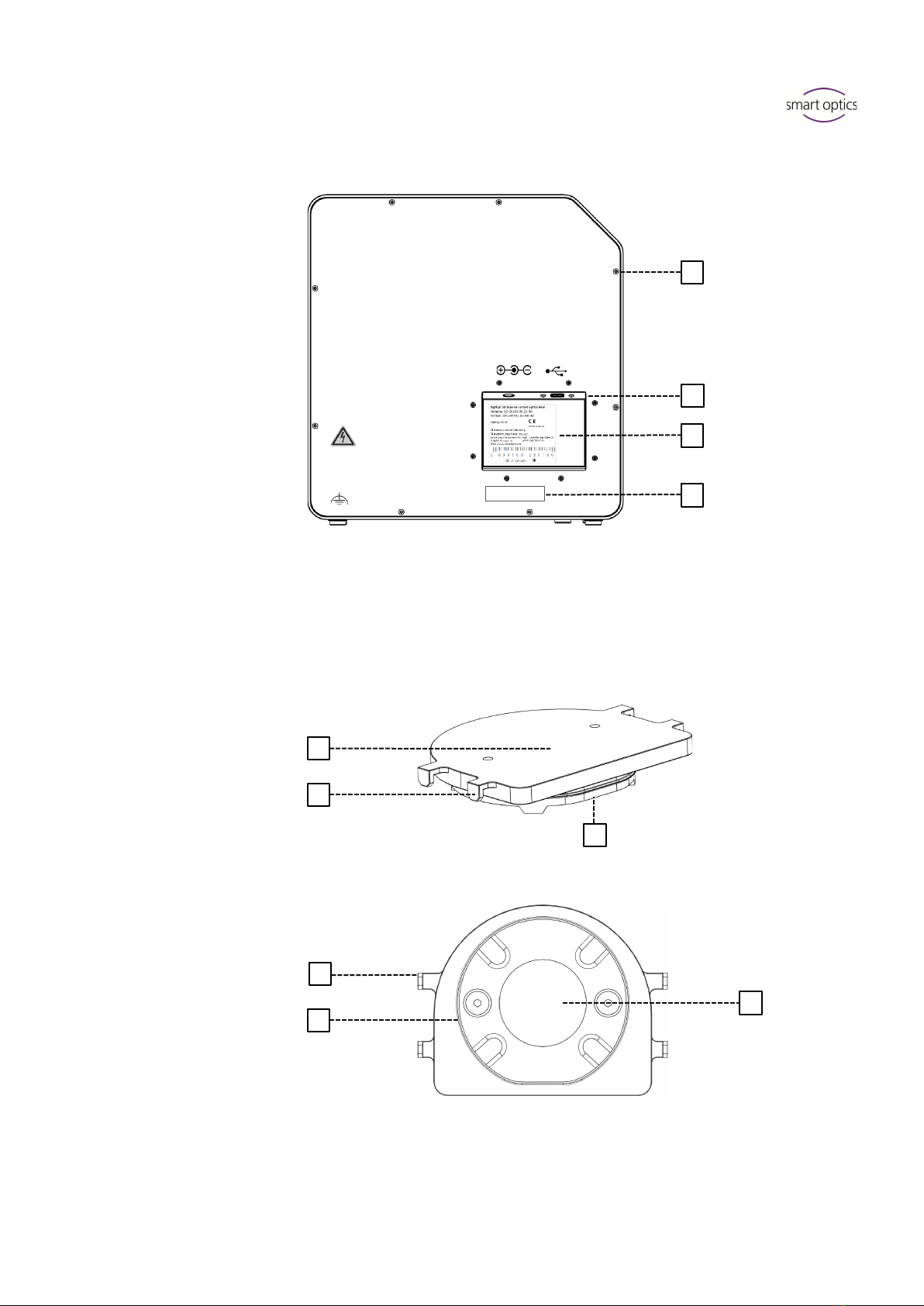
Rear
5.2
Accessories
5.2.1
Universal Plate
View from Above
View from Underneath
Key
1 Rear panel screw connection
2 Ports (power, USB)
3 Type plate
4 Sensor number
Key
1 Place for jaw models
2 Fixing hooks for rubber bands
(simple occlusion)
3 Plate type
Splitex/Adesso Split®
3a Magnetic adhesive disc
3
4
2
1
Serialno 3D-Sensor
SO-20293.00-23-001
1
2
3
2
3
3a

Operating Manual smart optics mini
Edition: 08-2023 Commissioning 11
5.2.2
3D Calibration Model
6Commissioning
6.1
Workplace
The scanner must be next to the PC, preferably on a laboratory table or
professional work table.
Check List
Laboratory, factory, manufacturing
Table
opaque, stable, low vibration
Place
337 × 347 × 322 mm (W × H × D)
Stability
2 × 9.5 kg
Indirect light
Temperature
18°C – 30°C
Wet room areas
NOTICE
Inaccurate measurements or device defect due to non-compliance
with workplace requirements
Avoid reflections on the measurement object. Protect the scan area
in intense ambient light (artificial light, sunlight), e.g. with opaque
foil.
Keep the scanner clean. Avoid, e.g., milling, grinding and sawing
work nearby.
Key
1 Hemispheres (for distance
measurement)
2 Cylinders (for height
measurement)
3 Label with model number
and reference values
1
2
3
1

Operating Manual smart optics mini
Edition: 08-2023 Commissioning 12
6.2
Unpacking
The original packaging is the best transport protection for scanners and
accessories. Keep them for later transporting.
1. Check the delivery for visible damage and discoloration on the shock
indicators (indicator label). Log and complain damages in accordance
to the shipping terms.
2. Transport the box to the workplace.
3. Open the box from above and remove the padding material.
4. Remove the accessory boxes (stored on the side).
5. Grab under the scanner and lift it out of the box.
6. Place the scanner on the work table next to the PC (distance max.
2 meters).
6.3
Connecting
6.3.1
Checklist Connections
Distance scanner – PC
max. 2 m
Sockets
min. 3
Power cable without power supply
Extension cable
Multi-plug
Socket adapters
USB Hub
USB extension
Carrying points
= allowed
= prohibited
5.

Operating Manual smart optics mini
Edition: 08-2023 Commissioning 13
NOTICE
Incorrect data transmission or device damage due to inappropriate
cabling
USB Hubs, USB extensions and USB cables longer than 2 meters
deteriorate the data transfer.
The scanner requires an external power supply for the power
connection.
USB cables or power supplies with the same specification as the
included ones are suitable as a replacement.
6.3.2
Procedure
1. Plug the USB and power connectors into the ports on the rear of the
scanner.
2. Connect the USB cable to a USB 3.0 port (blue) on the back of the PC.
3. Connect the plug-in power supply to the socket. If necessary, insert a
socket adapter in between (not included).
Once connected, the scanner can stand close to the wall.
USB 3.0
Hollow plug connector

Operating Manual smart optics mini
Edition: 08-2023 Commissioning 14
6.3.3
Attaching the Rotary Swivel Unit
The rotary swivel unit is delivered separately in a box.
NOTICE
Malfunction due to damage to contact surfaces
The contact surfaces on the rotary swivel unit and on the attachment
plate in the scanner are sensitive electronic components for the
transmission of data and electricity.
Do not touch the contact surfaces.
Avoid soiling or mechanical damage.
1. For fixing in the scanner, hang the rotary swivel unit from above on the
holding pins of the attachment plate.
2. Press against the rotary swivel unit to snap it into place on the lower
retaining pins.
6.4
Installing
6.4.1
Requirements
Does the PC meet the system requirements?
If you are using a notebook: connection to the electricity supply system
is required.
Are all updates for Windows and drivers installed?
Does the virus protection allow the scan software to run?
Does the Windows user have the right to run setups and apps?
5
1. 2.
Click!

Operating Manual smart optics mini
Edition: 08-2023 Commissioning 15
6.4.2
Installation
1. Insert the scanner-specific data carrier into a suitable PC port and open
the drive in Windows Explorer.
2. Execute the dental Scan.exe setup file by double-click.
3. Follow the instructions of the Installation Wizard.
4. Apply the default values. This simplifies the support and the setup of
interfaces.
The program files are installed, an entry in the start menu and a
desktop icon are available.
6.4.3
Upgrades
New versions of the scan software are available free of charge.
smart optics recommends using the current version.
www.smartoptics.de | Download Center (Software + Release-Notes)
Install an upgrade to the same destination folder as the previous
version to replace it.
6.5
Calibration
Calibration is a prerequisite for correct measurements and the last step of
commissioning. For calibration you will need:
the 3D calibration model,
the universal plate with adhesive pads,
the data carrier with scanner-specific calibration data.
6.5.1
Positioning the 3D Calibration Model
1. Cover the surface of the universal plate completely with adhesive pads,
at least three strips (product from the scope of delivery or comparable
specification, no other adhesive material).
2. Firmly press the 3D calibration model onto the universal plate (round to
round, straight to straight).
3. Place the universal plate with the 3D calibration model on the base
plate of the scanner (rounding inwards).
Desktop icon dental scan

Operating Manual smart optics mini
Edition: 08-2023 Commissioning 16
The adhesive pads can remain on the universal plate.
6.5.2
Calibration Procedure
Calibration is mandatory for commissioning. How to proceed:
1. Turn on the scanner (front LED pressure switch).
2. Insert the scanner-specific data carrier into the PC port.
3. Start the scan software. You will be asked to identify the folder
containing the calibration data.
4. Select the SO-20293... folder on the data carrier. After confirmation, the
calibration data is automatically copied to the correct destination
folder.
5. The scan software requires a calibration.
6. For #1 and #2, enter the values from the label of the 3D calibration
model (exact values with commas and decimal places).
7. Now position the 3D calibration model.
Desktop icon dental scan
Label with sample values
No.
1234
#1
52,6789
#2
9,9876
15
3.

Operating Manual smart optics mini
Edition: 08-2023 Scanning 17
8. Start the calibration. Wait until the final message.
After successful calibration, you can start scanning.
Data backup
Calibration data is not transferable to other scanners.
After initial installation, the calibration data are permanently available for
operation and calibration.
File path:
C:\ProgramData\3D-Scanner\DeviceCharacteristics\Sensors
Store the data carrier for possible reinstallation of the scanner.
7Scanning
7.1
General Information
The information in this manual is focused on handling. Detailed
instructions for scanning can be found integrated in the scan software or
in the user manual.
Tips on specific projects can be found in an instruction or training.
Scanning with Attached Small Parts
Prosthetic small parts or modeling can be scanned on the jaw model:
Mush bite as a representative of the antagonist jaw in scan mode
single jaw,
Gingiva and wax-up for segments with corresponding marking,
Scan bodies for segments with the indication implant.
Attach the small parts to the jaw model (with removable glue on a few
points).
Mattifying the Scan Object with 3D Scan Spray
Reflective or dark scan objects must be matted with 3D scan spray
(specified for dental technology, very finely grained).
Without matting, the scan result becomes worse. Use 3D scan spray
outside the scanner.
Spray the scan object thinly and evenly, do not touch the spray layer.
23

Operating Manual smart optics mini
Edition: 08-2023 Scanning 18
Service Position of the Rotary Swivel Unit
When positioning scan objects, the rotary swivel unit can be moved
unintentionally. As a result, the position of the rotary swivel unit stored in
the scan software no longer corresponds to the actual position.
Correct the position of the rotary swivel unit with the Service Position
function (after positioning, before scanning).
7.2
Scanning a Jaw Model
7.2.1
Jaw Model on Mounting Plate
Jaw models on a mounting plate of type Splitex/Adesso Split®with
magnetic adhesive disc can be scanned without further mounting.
Place the Splitex/Adesso Split®mounting plate directly on the base
plate of the scanner.
7.2.2
Jaw Model on Universal Plate
Jaw models without mounting plate and articulated jaw models on non-
Splitex/Adesso Split®mounting plates are scanned on the universal plate.
The universal plate must be covered with at least three strips of adhesive
pads.
1. Press the jaw model or mounting plate firmly onto the adhesive pads
(bottom towards centre, dental arch towards rounding). Test the fixture
by gently turning and tilting.
2. Place the universal plate on the base plate of the scanner (rounding
inwards).
2.

Operating Manual smart optics mini
Edition: 08-2023 Scanning 19
7.3
Jaw Models in Simple Occlusion
Jaw models in simple occlusion are scanned on the universal plate. The
simple occlusion is closed with rubber bands (texture: new, stable, about
0.4 cm thick). Ring rubbers and cruciate rubbers are possible. The material
does not interfere with the vestibular scan.
Rubber Band Attachment
1. Loosely place the UJ model in occlusion on the LJ model.
2. Select one of the following methods:
Form a long rubber ring into an eight and place it buccally over the
UJ model.
Place two short rubber rings x-shaped over the UJ model.
Place a cross rubber band around both jaw models so that the
crosses are on top and underneath and the bands are tensioned in
an x-shape.
3. Firmly press the connected jaw models onto the universal plate (with
adhesive pads). Test the fixture by gently turning and tilting.
4. Wrap the rubbers around the hooks on the universal plate, if
necessary, several times until the rubber is taut.
7.4
Scanning Articulator
Mean-value vestibular scans can be created with all common articulators.
With AMANN GIRRBACH Artex® and Baumann Dental Artist/arTO®,
condyle-related vestibular scans are possible.
7.4.1
Articulator Workflow
The scan software guides you through the following steps:
Removing the rotary swivel unit.
Putting the articulator in front of the camera.
Starting the scan (with timer).
Removing the articulator.
Reattaching the rotary swivel unit.
min. 8.5 cm
max. 8 cm
Hooks
View from the rear
View frow the side
Operating Manual smart optics mini
Edition: 08-2023 Scanning 20
You can change the steps positioning the articulator and starting the scan.
With a little practice, you will save time. You can change the timer, i.e. the
waiting time until the scan, in the software settings (5 seconds by default).
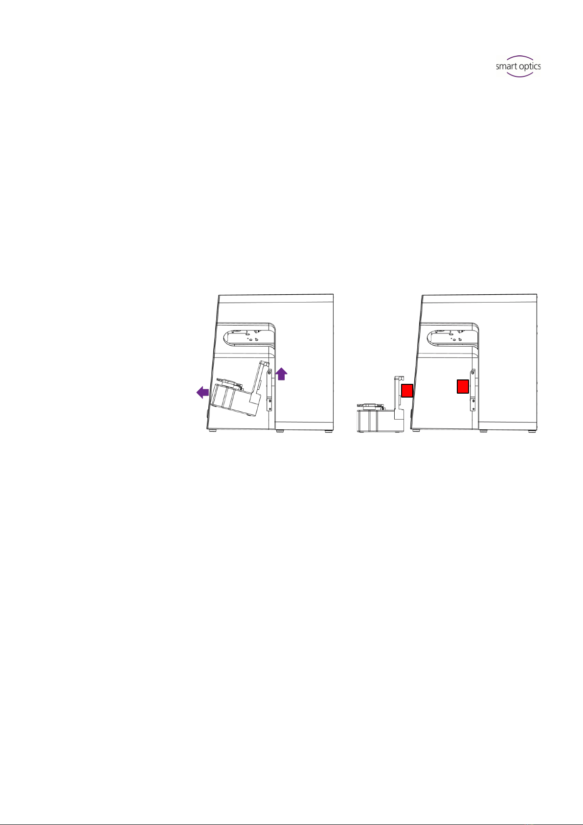
7.4.2
Rotary Swivel Unit
Wait until the scan software requires the rotary swivel unit to be removed.
1. Pull the rotary swivel unit off the attachment plate in the scanner
(slightly forward, then lift off the holding pins).
2. Place the rotary swivel unit in a protected place.
The contact surfaces must not be soiled or touched.
After the scan, wait until the scan software requires the rotary swivel unit
to be attached.
7.4.3
Positioning the Articulator
1. If necessary, remove the upper support pin.
2. Place the articulator before the attachment plate of the scanner.
3. Tilt the articulator so that the dental arch is facing the 3D sensor. Check
the alignment in the scan software (live image).
4. Wait for the timer in the scan software. The articulator must remain
motionless until measurement. The scan software reports when the
articulator can be removed.
14
1.
2.
Table of contents
Other Smartoptics Medical Equipment manuals


Popular Medical Equipment manuals by other brands

LeMaitre
LeMaitre TRIVEX System Operation & service manual

Bionet
Bionet BM1 user manual

B. Braun
B. Braun INFUSOMAT Secura operating instructions

Contec Medical Systems Co.
Contec Medical Systems Co. PM10 user manual

Hillrom
Hillrom TruSystem 7500 U14 Instructions for use

MicroPace
MicroPace StimLab User instruction manual


Hillrom
Hillrom Primo P02033 user manual

HEALTH RIDER
HEALTH RIDER Sotfstrider S600 Installation

Hadeco
Hadeco Bidop ES-100V3 operating manual

OneTouch
OneTouch Ping Quick reference sheet

B. Braun
B. Braun Aesculap MINOP Instructions for use/Technical description

Mind Media
Mind Media NeXus-10 MKII quick start