LeMaitre TRIVEX System Installation and operating instructions

LeMaitre
VASCUL AR
Outlines:
Original Artwork:
TRIVEX® System
TRIVEX® System
Operation/Service Manual - English
Système TRIVEX®
Manuel d’Utilisation / Entretien – Français
TRIVEX® 浅表静脉曲张动力去除系统
使用说明 - 简体中文

2
TABLE OF CONTENTS
PREFACE
This manual contains information you need to operate and maintain the LeMaitreVascularTRIVEX® System. It is essential that you read and understand all the
information in this manual before using or maintaining the system.
TABLE OF CONTENTS
Device Description 3
Indications for Use 3
Contraindications 3
Warnings 3-4
Precautions 4-5
System Components 5
Resector Handpiece 5
TRIVEX System Illuminator 5
Unpacking the Components 6
Assembling the Control Unit to Cart 6
Assembling the Handle to Mast 6
TRIVEX System Control Unit Front Panel 6
Console Controls and Functions 7
Power Switch 8
Fuse Panel 8
Preoperative Setup 8
Power Up 8
Tumescence Supply Setup 9
Resector Handpiece Saline Supply Setup 9
Connecting the Resector Handpiece and Resector 9-10
Connecting the Illuminator 10
Operation 10
Cautions 10
Resector Control 10-11
Resector Handpiece Irrigation Control 11
Resector Speed 11
Cutting 11
Window Lock 11
TRIVEX System Illuminator Irrigation 11
TRIVEX System Illuminator Control 11
Cleaning And Sterilization 12
Resector Handpiece 12
TRIVEX System Control Unit and Footswitches 12
Fiber Optic Cable 12
TRIVEX System Illuminator 12
Maintenance 12-13
Electrical Interference 12
Environmental Protection 12
Preventative Maintenance 12
Recommended Periodic Cleaning 13
Service 13
Service Philosophy 13
ReplacingThe Lamp 13
TRIVEX System Fuses 13
Returning theTRIVEX System Control Unit 13-14
Troubleshooting 14
Technical Specications 15
Ordering Information 15-16
Guidance and Manufacturer’s Declaration –
Electromagnetic Emissions 16
Guidance and Manufacturer’s Declaration
- Electromagnetic Immunity 16-17
Guidance For Separation Distances 17
Warranties 19
Service Replacement Units Warranty 19
Replacement Program 19
Repair Service Program 19
Training Program 19
Symbol Legend 60
Figures
1. Component Identication 5
2. Assemble Control UnitTo Cart 6
3. Control Unit Front Panel 6
4. Control Unit Display 7
5. Control Unit Rear Panel 8
6. Tubing Connections 9
7. Fiber Optic Cable Inspection 10
8. Resector Handpiece Controls 10
9. Lamp 13

3
DEVICE DESCRIPTION
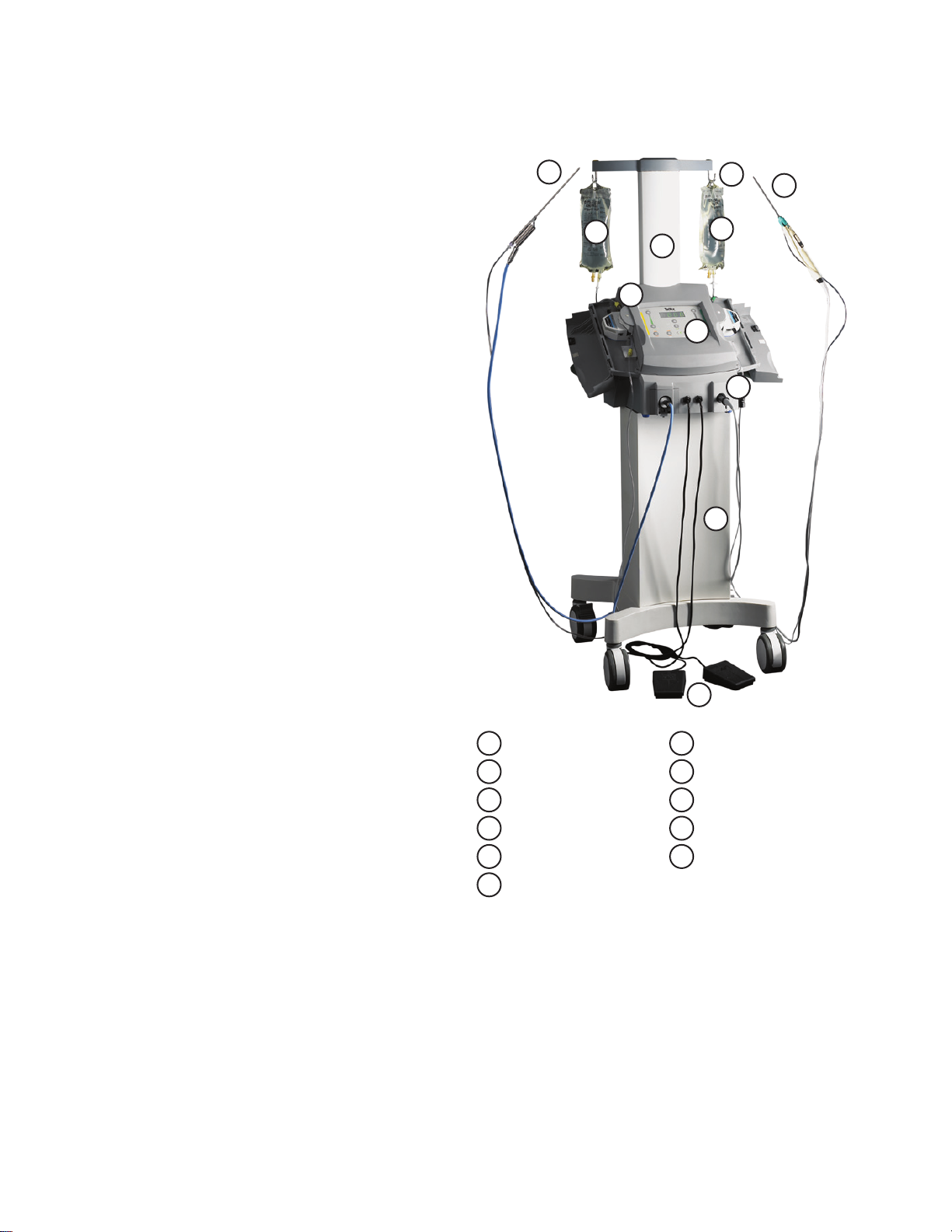
TheTRIVEX System provides controls for the operation of the light source for the Illuminator, the tumescent pump, the saline pump, and the mode and variable
speed operation of the Resector Handpiece. The TRIVEX System uses a pair of peristaltic pumps to provide irrigation and tumescence anesthesia for the
Transilluminated Powered Phlebectomy procedure.The left hand pump is dedicated to providing the tumescence anesthesia via the TRIVEX System Illuminator.
The right hand pump is dedicated to providing saline to the TRIVEX Resector Handpiece for resector tip irrigation.TheTRIVEX System uses a metal halide arc lamp
to provide intense, white light via the TRIVEX System Illuminator for transillumination.The illuminator connects with ber optic cables to the TRIVEX System to
provide transillumination during endoscopic resection of supercial varicosities of the lower extremities. The Resector Handpiece drives the Resector and features
push-button controls for Resector operation.The Cart provides a mobile base for the Control Unit and a mast for hanging the saline and tumescent solution
irrigation bags.The Footswitch causes air pressure to activate a switch inside the Control Unit which turns on the tumescence pump.
TheTRIVEX System is intended for use by vascular or general surgeons for treatment of patients of all ages and sexes that require removal of varicose veins.
INDICATIONS FOR USE
TheTRIVEX System is indicated for use in ambulatory phlebectomy procedures for the resection and ablation of varicose veins.
CONTRAINDICATIONS
Use of theTRIVEX System is contraindicated in situations where ambulatory phlebectomy is contraindicated.
WARNINGS
Please read this manual before using the TRIVEX System.The brief operating instructions in this guide will make the system easier to use, while the
recommended service and maintenance procedures will ensure optimal performance and reliable use. As with any surgical instrument, there are important
health and safety considerations. These are listed below and reiterated within the text.
Prior to using theTRIVEX System, it is essential that all components of the system be inspected for damage that can negatively impact the equipment
performance.The inspection should include all equipment to be used in surgery, including the illuminator, handpiece, cables, and accessories.
When removing the TRIVEX System and accessories from the shipping container, inspect contents to ensure that all components from the“Unpacking the
Components”section are available.
Contact your LeMaitreVascular Representative if damage is noted.
• Before using theTRIVEX System for the rst time, you should review all available product information. Surgeons should become familiar with this surgical
technique and theTRIVEX System. You should be experienced in ambulatory phlebectomy surgery using powered instruments. Healthy tissue can be
injured by improper use of theTRIVEX System resector. Use every available means to avoid such injury.
• TRIVEX Resector Kits are packaged as a set.They must be used as supplied. Do not interchange resector components.
• Illuminator inow tube sets and resector kits are provided STERILE and are for single use only. Do not reuse. Do not resterilize. Prior to use, inspect the
product package for signs of damage or tampering. Discard any opened and unused product. Do not use after the expiration date.
• Resterilization and/or re-use of the Illuminator Tube Sets or Resector Kits may cause mechanical damage to these products. This may result in injury to the
patient or user.
• TheTRIVEX System pumps should not be running while setting up the tubing. Injuries to the operator’s hands can occur.
• Work exclusively with sterile substances, sterile uids, and sterile accessories.
• This system is intended only for use with exible uid containers and uid bags. Glass containers or bottles may break, and there is a risk of implosion.
• Use of bags or containers not approved for this system, or large and/or lopsided loads, may cause the device to tip over.
• If visualization is lost during any point in the procedure stop resecting immediately.
• Excessive pressure of theTRIVEX resector against the vessel or prolonged activation of theTRIVEX resector in a stationary position may result in perforation
of the resector through the limb surface.
• Do not hold the light source shutter open without a ber optic cable in place. Failure to observe this precaution may result in eye injury.
• During procedure, avoid prolonged contact of the Illuminator tip to patient tissue or ammable materials.The Illuminator tip may reach high temperatures
due to high-intensity light transmission.
• DANGER: Risk of explosion if used in the presence of ammable anesthetics.
• When the light source is turned on, do not look directly at the metal halide arc lamp without protective goggles.
• To prevent electrical shock, do not remove theTRIVEX System console cover. There are no user-serviceable components inside. Dismantling the equipment
will void the warranty. Refer servicing to LeMaitreVascular.
• To prevent electrical shock, connect the power cord to a properly-wired grounding receptacle only.
• To prevent electrical shock, unplug the unit from the electrical outlet before attempting to replace the fuses.
• Use extreme caution:The high internal pressure of the lamp may cause an explosion, regardless of whether the lamp is cold or hot. Always wear protective
clothing and a face mask when handling the lamp.
• Hazardous high voltage and energy are present at the output and in the internal circuitry of this unit.
• If this unit is congured as part of a system, the entire system should be tested for compliance with IEC 60601-1.
• If the leakage current of the congured system exceeds the limits of IEC 60601-1, install an appropriately rated UL 60601-1/IEC 60601-1 approved isolation

4
transformer and retest the system.
• In some cases, high voltage may persist after the power has been removed. Only personnel qualied to service electronic equipment should operate or
troubleshoot an“uncased”power supply.
• Dangerous voltages are present during leakage current testing. DO NOTTOUCH theTRIVEX System while power is applied.
• HIGHVOLTAGE (1500VAC) is present during dielectric strength and Hi-Pot testing. Exercise extreme caution while operating the dielectric strength tester
or the Hi-Pot tester to prevent personal injury from electrical shock or damage to the equipment. Ensure that only authorized personnel are in the test area
during the tests.
• To avoid re hazard, use only fuses of the correct type, voltage rating, and current rating.
• The use of accessory equipment not complying with the equivalent safety requirements of this equipment may lead to a reduced level of safety of the
resulting system. Consideration relating to the choice shall include:
• Use of the accessory in the patient vicinity.
• Evidence that the safety certication of the accessory has been performed in accordance to the appropriate IEC 60601 Standard.
PRECAUTIONS
• U.S. Federal law restricts this device to sale by or on the order of a physician.
• Prior to use, examine the device(s) for possible damage to assure proper functioning. If damaged, do not use.
• Verify that the resector handpiece and its cable are sterile.
• Verify that the Illuminator, Light Guide and adaptors are sterile.
• Check to ensure that the resector(s) required for the procedure are available.
• Verify that the Preoperative Setup has been successfully completed.
• Only LeMaitre Vascular DisposableTRIVEX Resector Kits can be used with the TRIVEX System. Resectors used with the TRIVEX System are for single use only.
Do not resterilize or lubricate the resectors. Dispose of the resectors after use.
• Use of reprocessed, single-use resectors may permanently damage, impede performance, or cause failure of your LeMaitreVascularTRIVEX System. Use of
such products may render any warranties null and void.
• Make sure the wheels on the TRIVEX System roller base are locked to prevent the system from rolling during setup and use.
• As in conventional ambulatory phlebectomy procedures, bruising, hematoma, and hemosiderin deposits have been observed in clinical studies utilizing
theTRIVEX System.
• Disconnect power cord before cleaning the unit.
• Do not sterilize or immerse theTRIVEX System console in disinfectant.
• To prevent moisture from entering the handpiece cable during sterilization ensure that the protective cap is screwed on completely. Moisture can damage
the cable or handpiece connectors.
• Do not allow the rotating portion of any resector to touch any metallic object such as the illuminator. Damage to both instruments is likely. Damage to the
resector can range from a slight distortion or dulling of the resector edge to actual fracture of the tip in vivo. If such contact does occur, inspect the tip. If you
nd cracks, fractures or dulling, or if you have any other reason to suspect a resector is damaged, replace it immediately.
• Excessive leverage on the resector does not improve cutting performance and, in extreme cases, may result in wear and degradation of the inner assembly.
• Do not cool the resector handpiece by immersing it in cold water.
• Do not operate the resector in the open air for an extended period.
• Use only theTRIVEX Light Source Adaptor (REF 7210375) with this system. Use of any other light source port adaptor may cause reduced light emission from
the ber optic cable.
• The power switch must be turned o, and the power cord disconnected from the power source, before attempting to replace the lamp.
• Replace the lamp only with an appropriate LeMaitre Vascular lamp (REF 7210115) as specied for theTRIVEX System. Use of any other lamp will void the
warranty.
• Lamp may be very hot. Use protective eyewear and gloves when handling lamp.
• Do not leave the operating light cord without an Illuminator attached on the patient or surrounding materials. The light cord tip may reach a high
temperature due to the high intensity light.
• This unit complies with IEC 60601-1. However, the user must be aware that this does not necessarily ensure protection of the unit against interference from
other devices.
• Do not operate at line voltage other than those stipulated on the back of the unit.
• Ensure that the available mains voltage matches the data listed on the label attached to the back of the control unit. Incorrect voltage can cause errors or
malfunction, and may permanently harm the equipment.
• Handle the unit with care. If the unit is dropped or damaged in any way, it must be returned immediately for service.
• Electrical safety testing should be performed by a biomedical engineer or other qualied person.
• This equipment contains electronic printed circuit assemblies. At the end of the useful life of the equipment it should be disposed of in accordance with any
applicable national or institutional related policy relating to obsolete electronic equipment.
• This equipment is designed and tested to minimize interference with other electrical equipment. However, if interference occurs with other equipment it

5
may be corrected by one or more of the following measures:
• Reorient or relocate this equipment, the other equipment, or both.
• Increase the separation between the pieces of equipment.
• Connect the pieces of equipment into dierent outlets or circuits.
• Consult a biomedical engineer.
• Equipment should be disposed of in accordance with local and/or federal
codes and requirements.
SYSTEM COMPONENTS
TheTRIVEX System consists of a variety of components:
• TheTRIVEX System control unit provides controls for the mode and speed
of theTRIVEX Resector, for activation and ow of the tumescence and
saline pumps, and for operation of the light source for theTRIVEX System
Illuminator.
• The console includes a display for resector speed and LED indicators for
pump ow rate.
• The four control buttons (tumescence pump, lamp, resector mode, and
saline pump) have lighted indicators above and below each push button.
These indicate the status of each component by illuminating steady
green, ashing green, steady orange, or ashing orange.
• The front of the control unit has ports for connecting the illuminator, two
footswitches, and resector handpiece.
• TheTRIVEX System stand provides a mobile base for theTRIVEX System
control unit and an irrigation mast for the saline and tumescence solution
irrigation bags.
• The 50 watt metal halide arc lamp provides intense, white light via the
TRIVEX System Illuminator.
• TheTRIVEX Resector Handpiece drives the LeMaitreVascular 4.5 mm
TRIVEX Resector (REF 7209514) and 5.5 mmTRIVEX Resector (REF
7209515), and features push-button controls for resector operation.
RESECTOR HANDPIECE
TheTRIVEX Resector Handpiece is a hand-held motor drive that is electrically
connected to the control unit via a 10 foot (3 meter) cable.The resector
handpiece drives the disposable resectors.
The resector handpiece and its cable are autoclavable (see“CLEANING AND
STERILIZATION”).
TRIVEX SYSTEM ILLUMINATOR
TheTRIVEX System Illuminator (REF 7210351) is used to instill tumescence
solution and to transilluminate the targeted varicosities. Please see theTRIVEX
System Illuminator Instructions for Use (R2596) for additional information.
1Fluid Bag Holder Hooks (x2)
2Saline Solution Bag
3Tumescence Solution Bag
4Irrigation Mast
5Control Unit
6Control Unit Display
1
11
10
9
8
7
6
5
4
32
Figure 1: Component Identication
7Connection Ports
8TRIVEX System Stand
9TRIVEX System Illuminator
10 TRIVEX System Resector Handpiece
11 Footswitch (x2)

6
UNPACKING THE COMPONENTS
Carefully unpack and inspect all components shipped with your LeMaitre VascularTRIVEX System. If any
parts are missing or damaged, contact your LeMaitreVascular representative. Save the carton and packing
materials in the event a component must be returned for repair.
ASSEMBLE CONTROL UNIT TO CART
1. Place the stand with roller base on a smooth level surface with the rear panel facing you.
2. Remove the 3/16”Allen wrench from the base of the irrigation mast. Using the Allen wrench, remove
the four bolts securing the rear panel to the roller base.
3. Align the base of the control unit with the top of the roller base and lower the control unit straight
down onto the roller base (gure 2).
4. For each of the four drawer latches located in the interior of the roller base: lift and engage the latch,
then turn the latch key one half turn clockwise. Fold the latch key at.
5. Replace the rear panel and reinsert the four bolts.
ASSEMBLE HANDLE TO MAST
6. Remove the four irrigation mast mounting bolts from the rear of the control unit.
7. Assemble the handle to the mast by: removing the two 1/4-20 x 5/8”socket head screws and
washers from the handle using the 3/16”Allen wrench and then place the handle inside the
box section of the mast weldment. Orient the handle so the threaded inserts align with the
hole openings in the box section of the weldment. Secure the handle with the two, 1/4-20 x 5/8”socket head screws and washers.
8. Fit the irrigation mast with handle onto the rear of the control unit and secure it with the four irrigation mast mounting bolts.
CAUTION: Make sure the wheels on theTRIVEX System roller base are locked to prevent the system from rolling during setup and use.
TRIVEX SYSTEM CONTROL UNIT FRONT PANEL
CONTROL UNIT FRONT PANEL
1. Tumescence Pump Door – covers the tumescence pump hardware.
2. Saline Pump Door – covers the saline pump hardware.
3. TRIVEX System Display – contains the push buttons and displays for system operation.
FRONT PANEL CONNECTORS
There are four connectors on the front panel:
4. Fiber Optic Cable Connection Port – self-closing port designed to accept theTRIVEX Light Source Adaptor (REF 7210375).
CAUTION: Use of any other light source port adaptor may cause reduced light emission from the ber optic cable or damage internal components, including the
light source bulb.
5. Two FootswitchTubing Connection Ports – accept tubing for the TRIVEX System footswitches.
6. Resector Handpiece Cable Connection Port (accepts the Resector Handpiece cable)
Figure 3: Control Unit Front Panel
1
3
2
456
Figure 2: Assemble Control Unit to Stand

7
8
9
7
19
10
11
12
14
15
13
17
16
18
LeMaitre
VASCULAR
TRIVEX®System
Figure 4: Control Unit Display
CONSOLE CONTROLS AND FUNCTIONS
7 Tumescence Pump ON/OFF Button Turns the tumescence pump ON or OFF
8 Tumescence Pump Flow LED Indicators Indicates the ow rate setting of the tumescence solution
9 Tumescence Pump Flow Increase / Decrease Buttons Increase or decrease the ow rate of the tumescence pump. Each press of a button results in the ow
rate increasing or decreasing by one level
10 Lamp ON / OFF Button Turns the lamp ON or OFF
11 Window Lock Control Holding down both Resector Speed Control increase/decrease buttons simultaneously engages the
Window Lock function
12 Resector Speed Increase/ Decrease Buttons Increase or decrease resector speed by 100 rpm with each button press
13 Resector Speed Display (rpm) Displays the current speed of the resector incrementally in 100 rpm steps over a range of 100 rpm to
1500 rpm
14 Resector Mode Select Button The Resector Mode button is used to change the resector direction between Oscillate, Forward, and
Reverse
15 Resector Mode Indicators When the resector is in Oscillate mode, a single arrow on each side of the Resector Mode Select button
illuminates green (<>)
When the resector is in Forward Mode, both right-side arrows illuminate green (>>)
When the resector is in Reverse mode, both left-side arrows illuminate green (<<)
16 Saline Pump Flow LED Indicators Indicates the ow rate setting of the Saline solution
17 Saline Pump Flow Increase / Decrease Buttons Increase or decrease the ow rate of the Saline pump. Each press of a button results in the ow rate
increasing or decreasing by one level
18 Saline Pump ON/OFF Button Turns the Saline pump ON or OFF
19 Status Indicators These indicators are located above and below the control buttons for the Tumescence Pump, Lamp,
Resector Mode, and Saline Pump.They indicate the component’s status by illuminating steady green,
ashing green, steady orange, or ashing orange

8
2
1
Figure 5: Control Unit Rear Panel
POWER SWITCH
The green rocker switch on the right side is the power ON/OFF switch for the entire system 1.
The switch is illuminated when the system is ON.
The three-prong electrical connector allows connection of the system to any 100 to 240 volt AC (50/60 Hz) source using the power cord supplied with the system.
The system power supply automatically detects the local power standard and adapts the system to that standard
FUSE PANEL
The control unit is protected by dual, 6.3 amp/250 volt time delay fuses mounted on the rear panel to the right of the green power switch 2.
NOTE: If system is turned o for any reason, wait at least 15 seconds before turning power back on.
PREOPERATIVE SETUP FOR USE IN A SURGICAL PROCEDURE
WARNING: Work exclusively with sterile substances, sterile uids, and sterile accessories.
There are ve main steps for preparing theTRIVEX System for use in a surgical procedure:
1. Power up - turn theTRIVEX System on and check for faults.
2. TRIVEX System IlluminatorTumescence supply setup - prepare theTumescence solution and tubing.
3. Resector Handpiece saline supply setup - prepare the saline irrigation and tubing.
4. Resector Handpiece setup - connect the Resector Handpiece and verify operation.
5. Connect theTRIVEX System Illuminator andTumescence Pump footswitches and verify operation.
POWER UP
CAUTION: Ensure that the available mains voltage matches the data listed on the label attached to the back of the control unit. Incorrect voltage can cause errors
or malfunction, and may destroy the equipment.
WARNING: To prevent electrical shock, connect the power cord to a properly- wired grounding receptacle only.
1. Plug the unit power cord into the rear panel connector and a grounded AC power source. The control unit power supply automatically detects the local
power standard and adapts the system to that standard.
2. Push the power switch on the rear panel to the ON ( I ) position.
3. TheTRIVEX System will start up with these defaults:
• Tumescence pump ow set to level four which corresponds to approximately 450 ml/min ow. Tumescence pump is OFF and Pump ON/OFF button is lit
steady orange.
• Saline pump ow is set to level one. Saline pump is OFF and pump ON/OFF button is lit steady orange.
• Resector Mode is set to Oscillate (<>). The Resector Mode button will be lit steady orange if no Resector Handpiece is connected. The button will be lit
steady green if a Resector Handpiece is connected.
• Resector Speed is set to 500 rpm.
• Lamp is OFF. Lamp ON/OFF button is lit steady orange.
NOTE: If the Resector Mode Select Button is ashing green or orange see “TROUBLESHOOTING”.
NOTE: If the Lamp ON/OFF Button is ashing orange see “TROUBLESHOOTING”.

9
TUMESCENCE SUPPLY SETUP
WARNINGS:
• This system is intended only for use with exible uid containers and
uid bags. Glass containers or bottles may break, and there is a risk of
implosion.
• Use of bags or containers not approved for this system, or large and/or
lopsided loads, may cause the device to tip over.
1. Hang the tumescence solution bag from the left hand arm of the
TRIVEX System irrigation mast.
NOTE: Fluid bags must only be hung on the bag holder hooks. Hang only one
bag per hook. Maximum allowable volume is 3 liters.
2. Open theTumescence Pump Door.
3. Move theTumescence Pump Handle to the open position to allow
loading of the tubing into theTumescence Pump.
4. Insert the tumescence solution tubing into theTumescence Pump, and
snap the yellow tubing ttings into the corresponding yellow brackets.
Ensure that the tubing rests securely in the tubing forks.
CAUTION: Use only the TRIVEX System Illuminator Inow Tube Set (REF
7209513).
WARNINGS:
• TheTumescence Pump should not be running while setting up the tubing. Injuries to the operator’s hands can occur.
• Tube sets are provided STERILE and are for single use only. Do not reuse. Do not resterilize. Prior to use, inspect the product package for signs of damage or
tampering. Discard any opened and unused product.
5. Close theTumescence Pump using theTumescence Pump Handle. Make sure the tubing forks do not pierce the tumescence solution tubing.
6. Connect the tubing to theTumescence solution bag.
NOTE: The Tumescence Solution tubing should only be connected to the TRIVEX System Illuminator.
7. Close theTumescence Pump Door.
RESECTOR HANDPIECE SALINE SUPPLY SETUP
1. Hang the Saline solution bag from the right hand arm of theTRIVEX System irrigation mast.
2. Open the Saline Pump Door.
3. Move the Saline Pump Handle to the open position to allow loading of the tubing into the Saline Pump.
4. Insert the Saline solution tubing into the Saline Pump, and snap the green tubing ttings into the corresponding green brackets. Ensure that the tubing
rests securely in the tubing forks.
CAUTION: Use only TRIVEX System Resector Kit tube sets (REF 7209514 or 7209515).
WARNING: The Saline pump should not be running while setting up the tubing. Injuries to the operator’s hands can occur.
WARNING: Tube sets are provided STERILE and are for single use only. Do not reuse. Do not resterilize. Prior to use, inspect the product package for signs of
damage or tampering. Discard any opened and unused product.
5. Close the Saline Pump using the Saline Pump Handle. Make sure the tubing forks do not pierce the saline solution tubing.
6. Connect the tubing to the Saline solution bag.
NOTE: The Saline Solution tubing should only be connected to the Resector Handpiece.
7. Close the Saline Pump Door.
CONNECTING THE RESECTOR HANDPIECE AND RESECTOR
CAUTION: Make sure the wheels on the TRIVEX System roller base are locked to prevent the system from rolling during setup and use.
1. Unscrew the protective cap from the connector end of the resector handpiece cable.
2. Connect the resector handpiece cable to the connection port on the front panel as follows: Orient the handpiece cable connector by aligning the white
double arrows on the connector with the white dot on the connection port.The handpiece cable is fully engaged when the white arrows and the white dot
are almost touching. Make certain the handpiece cable is fully inserted into the connection port.
3. Press and hold the Run button on the resector handpiece to conrm operation. The resector handpiece motor action can be observed by looking inside the
distal end of the resector handpiece.
4. Remove the resector from the sterile package and insert the resector into the resector handpiece per theTRIVEX Resector Instructions for Use (R2590).
5. Press the Run button and observe the resector action to verify that it is properly installed.
6. Set the window lock position as described in the Operation section of this manual.
Figure 6: Tubing Connections

10
NOTE: The default directional mode setting for the resector handpiece is Oscillate.
7. Use the Resector Mode Select Button on the console to verify Forward and Reverse modes.
NOTE: If the Resector Mode Select Button is ashing green or orange, there is a problem with the resector handpiece. See the Troubleshooting section.
8. Connect the saline supply line from the Saline Pump to the inow portal on theTRIVEX System resector.
9. Connect the suction by sliding the suction tubing onto the outow portal on the proximal end of the resector handpiece.
NOTE: It is recommended that suction of -600 mm Hg be used for optimal resection performance.
CONNECTING THE ILLUMINATOR
WARNING: Do not hold the shutter open without a ber optic cable in place. Failure to
observe this precaution may result in eye injury.
1. Check the ber optic cable for damage. Cuts, abrasions, or tears in the silicone sheath
covering the ber optic cable will reduce overall light transmission.
2. While aiming one end of the cable toward a bright light, inspect the other end for
damaged bers, e.g., black dots or dark areas (Figure 7). Excessive numbers of broken
bers in the cable will result in reduced light transmission.
3. Connect theTRIVEX System Illuminator to the instrument end of the ber optic cable
using the ACMI® instrument end adaptor (REF 2141) included with theTRIVEX System.
4. Attach theTRIVEX Light Source adaptor (REF 7210375) to the system end of the ber
optic cable. Press the shutter button and insert the light source end of the ber optic
cable into the light source port. To remove the cable, press the shutter button and then
withdraw the cable.
CAUTION: Use only the TRIVEX Light Source adaptor (REF 7210375) with this system. Use of any
other light source port adaptor may cause reduced light emission from the ber optic cable
and may cause damage to the system light bulb.
5. Connect theTumescence inow tubing to the Illuminator.
6. Connect theTumescence Pump Footswitches to the Footswitch connectors.
NOTE: The TRIVEX System starts up with the Tumescence pump OFF. The Tumescence Pump must
be turned on using the Tumescence Pump ON/OFF button before the footswitches will work.
WARNING: Possible explosion hazard if used in the presence of ammable anesthetics.
OPERATION
CAUTIONS
• Before using theTRIVEX System for the rst time, you should review all available product information.
• Verify that the resector handpiece and its cable are sterile.
• Verify that the illuminator and the light guide cable are sterile.
• Check to ensure that the resector(s) required for the procedure are available.
• Verify that the Preoperative Setup has been successfully completed.
• Only LeMaitre Vascular DisposableTRIVEX Resector Kits can be used with the TRIVEX System
Control Unit.The resectors are intended for single use only. Do not resterilize. Do not lubricate
resectors. Discard the devices after use.
• Make sure the wheels on the TRIVEX System roller base are locked to prevent the system from
rolling during setup and use.
RESECTOR CONTROL
There are two button controls on the Resector Handpiece (Figure 8). Press and hold the Run button
to start the resector.The resector will run in the selected mode (Forward, Reverse, or Oscillate) until
the button is released.
On startup, theTRIVEX System will default to Oscillate mode.The Resector Mode Select button
indicator will glow green when a resector handpiece is connected.
For problem conditions with the Resector Handpiece theTRIVEX System will light the indicator
bracketing the Resector Mode Select button.There are three possible indicators: a ashing orange
light indicates a stalled motor or high current condition; a steady orange light indicates the
TRIVEX System cannot detect a Handpiece; and a ashing green light indicates a problem with the
Handpiece itself. (See“TROUBLESHOOTING”for additional information.)
TheWindow Lock function determines the stop position of the inner resector relative to the
Figure 7: Fiber Optic Cable Inspection
Figure 8: Resector Handpiece Controls
Run Button
Window Lock Set
Button

11
opening in the outer resector. Press and hold theWindow Lock Set button to set theWindow Lock. TheWindow Lock will rotate while the button is pressed.
Release the button when theWindow Lock has reached the desired position.
NOTE: The Resector Window Lock can also be set from the TRIVEX System control console unit console by pressing and holding the Resector Speed Increase and
Decrease buttons simultaneously.
RESECTOR HANDPIECE IRRIGATION CONTROL
Turn the Saline Pump on using the Saline Pump ON/OFF Button.TheTRIVEX System defaults to a Saline Pump Flow setting level of one on startup. This is
approximately 50 ml/min.The Saline Pump will only run while the Resector Handpiece Run button is held down.
The Saline Pump Flow can be increased or decreased by pressing the Flow Increase or
Flow Decrease buttons located above and below the Saline Pump Flow Display.The Saline Pump has ve Flow settings.The approximate ow rates for the pump
fall between 50 ml per minute and 175 ml per minute.
NOTE: The Saline Pump ON/OFF Button glows orange when the pump is o and glows green when the pump is on.
NOTE: While operating the Resector Handpiece be sure that the saline pump is turned ON.
RESECTOR SPEED
The resector speed display indicates the current speed of the resector in rpm. When theTRIVEX System is turned on, the system is set to a default resector speed
of 500 rpm. Use the increase and decrease push-buttons below the console display to set the actual speed of the resector. Pressing the increase and decrease
buttons simultaneously will enable theWindow Lock function.
Each press of a button will increase or decrease the speed of the resector by 100 rpm. The Resector speed can be set to any 100 rpm increment between 100 rpm
and 1500 rpm.
The Forward (>>) and Reverse (<<) arrows that bracket the Resector Mode Select button indicate the resector direction.
CAUTION: Do not allow the rotating portion of the resector to touch any metallic object such as the illuminator. Damage to both instruments is likely. Damage to the
resector can range from a slight distortion or dulling of the resector edge to actual fracture of the tip in vivo. If such contact does occur, inspect the tip. If you nd cracks,
fractures or dulling, or if you have any other reason to suspect a resector is damaged, replace it immediately.
CAUTION: Excessive leverage on the resector does not improve cutting performance and, in extreme cases, may result in wear and degradation of the inner assembly.
CUTTING
Cutting takes place when the resector edge of the inner tube rotates across the resector’s outer window.The resector action alternately opens and closes the
window to modulate the suction ow.
WINDOW LOCK
With the Window Lock feature, the resector handpiece can be set to stop the resector in a specic position.The window can be fully opened or closed, or
somewhere in between, depending on the technique requirement. Pressing theWindow Lock button on the resector handpiece, or pressing the increase and
decrease buttons on the console simultaneously will engage the Window Lock function.
CAUTION: Do not operate the resector in the open air for an extended period, as the lack of irrigation may cause the resector to overheat and seize.
TRIVEX SYSTEM ILLUMINATOR IRRIGATION
Turn theTumescence Pump on using the Tumescence Pump ON/OFF Button.TheTRIVEX System defaults to aTumescence Pump Flow setting level of four on
startup approximately 450 ml/min.
TheTumescence Pump Flow can be increased or decreased by pressing the Flow Increase or Flow Decrease buttons located above and below theTumescence
Pump Flow Display. TheTumescence Pump has ve Flow settings. The approximate ow rates for the pump fall between 300 ml per minute and 500 ml per
minute.
NOTE: The Tumescence Pump ON/OFF Button glows orange when the pump is o and glows green when the pump is on.
Press and hold either footswitch to start theTumescence Pump. Release the footswitch to stop the pump.
NOTE: The TRIVEX System starts up with the Tumescence pump OFF. The Tumescence Pump must be started using the Tumescence Pump ON/OFF button before the
footswitches will work.
TRIVEX SYSTEM ILLUMINATOR CONTROL
Turn the illuminator lamp on using the Lamp ON/OFF Button.When the TRIVEX System lamp is rst turned on the button will ash green for 10 seconds while the
system does a lamp check.
When the lamp is o the Button glows orange. Each time the lamp is turned o, it will enter a 30-second cool-down cycle.This 30-second cycle is in addition to
the 10-second lamp check cycle. As a result, the lamp button can ash green for up to 40 seconds before switching to a steady green glow.
In the event that the lamp does not light after the self-check cycles, the lamp button will ash orange.

12
CLEANING AND STERILIZATION
RESECTOR HANDPIECE
Follow these steps after each procedure to sterilize the resector handpiece:
1. Dispose of the resector and tube set used during the procedure following standard protocols for disposal of biohazardous waste.
CAUTION: Resectors and tube sets used with theTRIVEX System are for single use only. Do not resterilize. Discard after use.
2. Disconnect the resector handpiece cable from the front panel. Screw the protective cap on to the connector end of the cable.
CAUTION: Do not disconnect the cable from the handpiece.
CAUTION: To prevent moisture from entering the handpiece cable during sterilization ensures that the protective cap is screwed on completely. Moisture
can damage the cable or handpiece connectors.
3. Set the suction to fully open by releasing the pinch valve on the suction tube.
4. Clean the unit thoroughly with soapy water by hand only. The unit may be immersed.
CAUTION: Do not use ultrasonic cleaners or automated washers to clean the handpiece.
5. Clean the drain tube with a brush. Rinse the unit thoroughly with water. Do not use saline or solvents such as alcohol or acetone.
6. Thoroughly dry the unit using compressed air to evacuate water out of crevices.
7. Sterilize the handpiece using one of the following methods:
• Steam, pre-vacuum, wrapped at 270° F to 275° F (132° C to 135° C) for four minutes.
• Steam, gravity method, wrapped at 270° F to 275° F (132° C to 135° C) for ten minutes.
CAUTION: Do not cool the resector handpiece by immersing it in cold water.
TRIVEX SYSTEM CONTROL UNIT AND FOOTSWITCHES
TheTRIVEX System control unit operates outside of the sterile eld and does not require sterilization. Sterilization and/or disinfection procedures will
damage the product and void the warranty. Follow these steps after each procedure to clean the control unit:
1. Disconnect the TRIVEX System from the electrical source.
2. Wipe the console with a clean damp cloth and mild germicide or isopropyl alcohol.
CAUTION: Do not sterilize or immerse the TRIVEX System console in disinfectant.
Wipe the footswitches and footswitch cables with a clean damp cloth.
FIBER OPTIC CABLE
See the Fiber Optic Cable Instructions for Use (R2603) for proper cleaning and sterilization procedures.
TRIVEX SYSTEM ILLUMINATOR
See theTRIVEX System Illuminator Instructions for Use (R2596) for proper cleaning and sterilization procedures.
MAINTENANCE
ELECTRICAL INTERFERENCE
CAUTION: This equipment is designed and tested to minimize interference with other electrical equipment. However, if interference occurs with other equipment
it may be corrected by one or more of the following measures:
• Reorient or relocate this equipment, the other equipment, or both.
• Increase the separation between the pieces of equipment.
• Connect the pieces of equipment into dierent outlets or circuits.
• Consult a biomedical engineer.
ENVIRONMENTAL PROTECTION
CAUTION: This equipment contains electronic printed circuit assemblies. At the end of the useful life of the equipment it should be disposed of in accordance with
any applicable national or institutional related policy relating to obsolete electronic equipment.
PREVENTATIVE MAINTENANCE
Recommended Electrical Safety Checks
Three safety tests are conducted on each unit during factory acceptance testing:
• Dielectric StrengthTest
• Ground Continuity Test
• Leakage CurrentTest
LeMaitre Vascular recommends that these tests be performed regularly to assure continued compliance with applicable safety requirements. These tests
should be conducted in accordance with specications IEC 60601-1.
CAUTION: Electrical safety testing should be performed by a biomedical engineer or other qualied person.
WARNING: HIGH VOLTAGE is present during electrical safety testing. Exercise extreme caution to prevent personal injury from electrical shock, or damage to the
equipment. Ensure that only authorized personnel are in the test area during the tests.

13
Recommended Periodic Cleaning
LeMaitre Vascular recommends periodic cleaning of the fan screens on the rear panel of theTRIVEX System control unit. Use a soft brush to loosen and
remove any dirt that may have collected on the fan screens.
CAUTION: Excessive dirt buildup may reduce air ow from the fans and cause overheating.
SERVICE
Appropriate servicing of theTRIVEX System involves eld replacement of fuses, the lamp damaged or worn handpiece cable, ber optic cable, or damaged
or worn power cord. All other repairs should be performed by LeMaitreVascular.
See“ORDERING INFORMATION”for a list of replacement parts.
SERVICE PHILOSOPHY
There are no user serviceable components inside theTRIVEX System Control Unit. Repairs and adjustments are to be performed only by LeMaitre Vascular
service centers.
If service becomes necessary, contact LeMaitreVascular Customer Service prior to returning the device to request a Return Goods Authorization (RGA)
number. Items to be serviced should be carefully repackaged and returned per instructions provided by LeMaitreVascular Customer Service. Daily rentals
are available as needed. A replacement program is available, contact your LeMaitreVascular representative for details.
NOTE: Product returned that is found to have been serviced by an unauthorized third party repair facility and/or sterilized with a sterilization method other than
one approved by LeMaitre Vascular will incur additional costs, regardless of warranty status.
REPLACING THE LAMP
WARNING: Do not touch the lamp with bare hands. Use gloves to avoid skin oils that will harm the lamp.
1. Pull knob on Lamp assembly drawer down and pull drawer out.
2. Disconnect Lamp
3. Using provided screwdriver, remove circuit boards (as necessary) and unlatch lamp.
4. Replace Lamp
5. Latch brackets, connect lamp, and reinstall circuit boards (as necessary)
CAUTION: Replace the lamp only with an appropriate LeMaitre Vascular Replacement Lamp (REF 7210115) as specied for the TRIVEX System. Use of any other
lamp will void the warranty.
CAUTION: Lamp may be very hot. Use protective eyewear/gloves when handling the lamp.
TRIVEX SYSTEM FUSES
The control unit is protected by dual, 6.3 amp/250 volt time delay fuses mounted on the rear panel to the right of the three- pronged electrical connector.
If the control unit fails to power-up when properly connected to a 100–240 volt (±10%) AC power source, check the fuses in the rear panel.
To replace the rear panel fuses:
WARNING: To prevent electrical shock, unplug the unit from the electrical outlet before attempting to replace the fuses.
1. Disconnect the unit from the power source.
2. Locate the fuse tray just to the right of the power cord.
3. Use a slotted screwdriver to press the tab on the side of the fuse holder in, toward the center of the fuse tray.
4. Slide the fuse tray out.
5. Replace the fuses with 6.3 amp/250 volt time delay fuses.
WARNING: To avoid re hazard, use only fuses of the correct type, voltage rating, and current rating.
6. Insert the tray into the holder until the tab click into place.
7. Reapply power to the unit.
NOTE: Blown fuses usually indicate a short circuit or a failed component. Make sure
components are properly interconnected. If the problem persists, contact LeMaitre
Vascular Customer Service for troubleshooting assistance.
RETURNING THE TRIVEX SYSTEM CONTROL UNIT
In the event of a System Error code or some other failure of theTRIVEX System Control Unit,
remove the unit from its stand and ship it back to LeMaitreVascular in its original box.
1. Unplug and remove the power cord from theTRIVEX System Control Unit.
2. Remove the footswitch connectors, ber optic cable and adaptor, resector handpiece
cable, and all tube sets.
3. Using the 3/16”Allen wrench located at the base of the irrigation mast, remove the
four mounting bolts and detach the irrigation mast.
Figure 9: Lamp
Lamp

14
4. Using the 3/16”Allen wrench, remove the four bolts securing the rear panel to the roller base. Remove the rear panel.
5. Locate the four drawer latches on the upper- interior of the roller base. For each of the four drawer latches: Lift the latch key and turn it one-half turn
counterclockwise.Then lift and disengage the keeper.
6. Lift theTRIVEX Control Unit straight up from the roller base.
7. Repack theTRIVEX Control Unit in its original carton and ship back per instructions provided by LeMaitreVascular.
TROUBLESHOOTING
SERVICE INDICATIONS
During system operation, theTRIVEX System runs a concurrent diagnostic routine in the background, checking inputs from the attached components. When
the system detects a condition that requires attention, an orange or green indicator light is lit on the front panel. In many cases, the system will continue to
operate normally, but occasionally allowable resector speed will be reduced. If the procedures below do not resolve the problem, the unit should be referred
to qualied personnel for service.
Symptom Possible Cause Remedy
TheTRIVEX System fails to come on when
power switch is pressed.
The unit is not connected to power. Plug into a power outlet of suitable rating. Ensure that both ends of the
power cord are properly connected.
Lamp assembly drawer is not fully closed. Check lamp drawer to be sure that it is fully seated into its housing.
Lamp ON/OFF button indicator light is
ashing green.
Lamp self-test. The lamp is running a self-test. Wait
10-40 seconds for self-test to nish.
Lamp ON/OFF button indicator light is
ashing orange.
Defective lamp. Replace the lamp. See Service/ Maintenance for instructions on
replacing the lamp.
The light output is low. The light cable is not in the light source
adaptor correctly.
Reseat the ber optic cable. Check to see if the light source adaptor is in
the correct position.
Illuminator defective. Replace the illuminator.
Defective lamp. Replace the lamp module.
Wrong light source portal adaptor attached
to ber optic cable.
Use only theTRIVEX System Light
Source adaptor (REF 7210375).
Resector Mode Select button indicator light
is ashing green.
Moisture in resector handpiece or resector
cable connectors.
Disconnect the cable from the control unit. Check the cable connector
for moisture. If wet, rinse the connector with distilled water and dry
completely.
There is a problem with the resector
handpiece.
If the ashing green persists, the resector handpiece is damaged;
contact your LeMaitreVascular representative.
No light from light guide. Light guide adaptor latch did not catch. Check light guide adaptor to ensure that it is fully seated into console.
Resector Mode Select button is ashing
orange while handpiece Run button is held
down.
The resector handpiece motor has stalled. Remove and inspect the resector. Replace with a new resector if
damaged.
Run the handpiece without a resector. If the handpiece is still
stalled, use alternate handpiece and contact your LeMaitreVascular
representative.
Resector Mode Select button indicator light
is ashing orange after handpiece Run
button is released.
High current warning for resector handpiece. Contact your LeMaitreVascular representative.
Resector Handpiece will not run and
Resector Mode Select button indicator light
is green.
Bad handpiece connector cable. Check cable connections. Make certain the handpiece cable is fully
inserted into the port on the front panel.
Resector Mode Select button indicator light
is steady orange.
Resector Handpiece not connected. Connect a resector handpiece to the
TRIVEX System.
Resector Speed Display reads E-01 through
E-15.
System Error. Note the error code and contact your
LeMaitre Vascular representative.
Tubing appears to be creeping through the
pump.
Tubing forks not tight enough. Tighten the tubing forks by one notch until tubing is secure, or
contact your LeMaitreVascular representative for specic adjustment
instructions.
No uid ow from peristaltic pump. Pump head is not latched. Check black pump closing lever to be sure it is fully closed.
Pump rollers have seized. Call Customer Service for return authorization.

15
TECHNICAL SPECIFICATIONS
TRIVEX SYSTEM CONTROL UNIT (7210386)
Dimensions: 22.6”wide x 24.2”deep x 64.0”high
Weight: 80 lbs
Power: 100–120/200–240VAC 50/60 Hz, 350VA
Equipment Classication: Protection against electrical shock class 1 with BF type applied part.
Protection against harmful ingress of water. (Ordinary equipment, none provided)
Degree of safety of application in the presence of ammable anesthetics with mixture of air, oxygen, or
nitrous oxide.
(Not suitable)
FRONT PANEL
Lamp ON/OFF Button: Turns the 50 Watt Metal Halide lamp On or O and displays current lamp status.
Resector Speed Display: 4 character digital display–actual speed for installed resector.
Resector Mode Select Button: Single momentary push button used to select the Resector Mode.
Resector Mode Display: Two left-facing arrows and two right-facing arrows-display resector mode: Forward (>>), Reverse (<<),
and Oscillate (<>).
Resector Speed Buttons: Two momentary push buttons for increasing and decreasing speed settings.
ResectorWindow Lock Display: Pressing and holding both the Resector Speed Buttons at the same time sets the ResectorWindow Lock.
Tumescence Pump Flow Buttons Two momentary push buttons for increasing or decreasingTumescence pump ow.
Saline Pump Flow Buttons: Two momentary push buttons for increasing or decreasing Saline pump ow.
Pump ON/OFF Buttons: Two momentary push buttons for starting or stopping the Saline pump or theTumescence pump.
Connectors: Light Source port, two Footswitch cable connectors, and a Resector Handpiece connector
REAR PANEL
Power ON/OFF: Rocker switch
AC Power: Detachable cord with a three-pin hospital-grade connector. Power input circuit automatically detects AC
power standard.
Fuses: Two 6.3 amp/250 volt time delay fuses (Littel Fuse, Inc., P/N 021806.3HXP).
TRIVEX RESECTOR HANDPIECE (REF 7210387)
Handpiece with push-button motor and window lock controls.
Length: 7.1”
Weight: 8.5 oz.
Equipped with 10-foot (3-meter) autoclavable, replaceable resector handpiece cable.
TRIVEX SYSTEM FOOTSWITCH (REF 7209791)
Two supplied.
ORDERING INFORMATION
TRIVEX SYSTEM COMPONENTS
REF DESCRIPTION
2141 VERSITIP ACMI Adaptor
7205180 Gemini Universal Light Guide
7209791 TRIVEX System Footswitch
7210351 TRIVEX System Illuminator
7210375 VERSITIP ,TRIVEX Adaptor
7210386 TRIVEX System Control Unit
7210387 TRIVEX System Resector Handpiece
7210414 TRIVEX System Cart
R2932 U.S. Power Cord
R2933 U.K. Power Cord

16
R2931 TUV/ EU Power Cord
R2927 China/ AUS Power Cord
TRIVEX SYSTEM DISPOSABLES/ACCESSORIES
REF DESCRIPTION
7205683 Autoclavable Storage and Sterilization Tray
7209513 Illuminator Inow Tubing
7209514 TRIVEX , 4.5 mm Blade andTubing
7209515 TRIVEX, 5.5 mm Blade andTubing
7210115 Replacement Lamp
GUIDANCE AND MANUFACTURER’S DECLARATION – ELECTROMAGNETIC EMISSIONS
Guidance and Manufacturer’s Declaration – Electromagnetic Emissions
The LeMaitreVascular TRIVEX System is intended for use in the electromagnetic environment specied below.The customer or the user of the LeMaitre VascularTRIVEX System
should assure that it is used in such an environment.
Emissions Test Compliance Electromagnetic Environment - Guidance
RF emissions
CISPR 11
Group 1 The LeMaitreVascular TRIVEX System uses RF energy only for its internal functions.Therefore, the
RF emissions are very low and are not likely to cause any interference in nearby electronic equip-
ment.
RF emissions
CISPR 11
Class A The LeMaitreVascular TRIVEX System is suitable for use in all establishments other than domestic
and those directly connected to the public low-voltage power supply network that supplies build-
ings used for domestic purposes
Harmonic emissions
IEC 61000-3-2
Class A
Voltage uctuations/ icker emissions
IEC 61000-3-3
Complies
GUIDANCE AND MANUFACTURER’S DECLARATION – ELECTROMAGNETIC IMMUNITY
Guidance and Manufacturer’s Declaration – Electromagnetic Immunity
The LeMaitreVascular TRIVEX System is intended for use in the electromagnetic environment specied below.The customer or the user of the LeMaitre VascularTRIVEX System
should assure that it is used in such an environment.
Immunity Test IEC 60601 Test Level Compliance Level Electromagnetic Environment - Guidance
Electrostatic (ESD) Discharge
IEC 61000-4-2
± 6kV contact
± 8kV air
± 6kV contact
± 8kV air
Floors should be wood, concrete or ceramic tile and the relative
humidity should be at least 30%.
Electrical fast transient/burst
IEC 61000-4-4
± 2kV for power supply lines
± 1kV for input/output lines
± 2kV for power supply lines
± 1kV for input/output lines
Mains power quality should be that of a typical commercial or
hospital environment.
Surge
IEC 61000-4-5
± 1kV dierential mode
± 2kV common mode
± 1kV dierential mode
± 2kV common mode
Mains power quality should be that of a typical commercial or
hospital environment
Voltage dips, short interruptions and
voltage variations on power supply
input lines
IEC 61000-4-11
<95% dip in UT for 1/2 cycle
60% dip in UT for 5 cycles
30% dip in UT for 25 cycles
>95% dip in UT for 5 sec
<95% dip in UT for 1/2 cycle
60% dip in UT for 5 cycles
30% dip in UT for 25 cycles
>95% dip in UT for 5 sec
Mains power quality should be that of a typical commercial
or hospital environment. If the user of the LeMaitre Vascular
TRIVEX System requires continued operation during power mains
interruptions, it is recommended that the LeMaitreVascular
TRIVEX System be powered from an uninterruptible power supply
or a battery.
Power frequency (50/60 Hz)
magnetic eld
IEC 61000-4-8
3 A/m 3 A/m The power frequency magnetic eld should be at levels
characteristic of a typical location in a typical commercial or
hospital environment
NOTE: UT is the a.c. mains voltage prior to application of the test level.

17
Conducted RF
IEC 61000-4-6
3Vrms
150 kHz
to 80 MHz
3Vrms Portable and mobile RF communications equipment should be
used no closer to any part of the LeMaitreVascularTRIVEX System,
including cables, than the recommended separation distance
calculated from the equation applicable to the frequency of the
transmitter.
Recommended separation distance
d=1.2 √(p..)
d=1.2 √(p..) 80 MHz to 800 MHz
d=2.3 √(p..) 800 MHz to 2.5 GHz
Where p is the maximum output power rating of the transmitter
in watts (W) according to the transmitter manufacturer and d is
the recommended separation distance in meters (m).
Field strength from xed RF transmitters, as determined by an
electromagnetic site survey,a should be less than the compliance
level in each frequency range.b
Interference may occur in the vicinity of equipment marked with
the following symbol:
Radiated RF
IEC 61000-4-3
3V/m
80 MHz
to 2.5 GHz
3V/m
NOTE 1: At 80 MHz and 800 MHz, the higher frequency range applies.
NOTE 2:These guidelines may not apply in all situations. Electromagnetic propagation is aected by absorption and reection from structures, objects, and people.
aField strengths from xed transmitters, such as base stations for radio, (cellular/cordless) telephones, land mobile radios, amateur radios, AM and FM radio broadcasts,
andTV broadcasts cannot be predicted theoretically with accuracy. To assess the electromagnetic environment due to xed RF transmitters, an electromagnetic site survey
should be considered. If the measured eld strength in the location in which the LeMaitreVascular TRIVEX System is used exceeds the applicable RF compliance level above,
the LeMaitre VascularTRIVEX System should be observed to verify normal operation. If abnormal performance is observed, additional measures may be necessary, such as
reorienting or relocating the LeMaitre VascularTRIVEX System.
bOver the frequency range 150 kHz to 80 MHz, eld strengths should be less than 3V/m.
GUIDANCE FOR SEPARATION DISTANCES
Recommended separation distances between portable and mobile RF communications equipment and the LeMaitre Vascular TRIVEX System
The LeMaitreVascular TRIVEX System is intended for use in an electromagnetic environment in which radiated RF disturbances are controlled. The customer or user of the
LeMaitre VascularTRIVEX System can help prevent electromagnetic interference by maintaining a minimum distance between portable and mobile RF communications
equipment (transmitters) and the LeMaitreVascular TRIVEX System as recommended below, according to the maximum output power of the communications equipment.
Rated Maximum Output Power of
Transmitter W
Separation distance according to frequency of transmitter M
150 kHz to 80 MHz
d=1.2 √p
80 MHz to 800 MHz
d=1.2 √p
800 MHz to 2.5 GHz
d=2.3 √p
0.01 0.12 0.12 0.23
0.1 0.38 0.38 0.73
1 1.2 1.2 2.3
10 3.8 3.8 7.3
100 12 12 23
For transmitters rated at a maximum output power not listed above, the recommended separation distance d in meters (m) can be estimated using the equation applicable to
the frequency of the transmitter, where p is the maximum output power rating of the transmitter in watts (W) according to the transmitter manufacturer.
NOTE 1: At 80 MHz and 800 MHz, the separation distance for the higher frequency range applies.
NOTE 2: These guidelines may not apply in all situations. Electromagnetic propagation is aected by absorption and reection from structures, objects, and people.

18
HARDWARE (CONTROL UNIT AND MDU)- NEW:
If you purchased a new device, then the following warranty applies:
Limited Product Warranty; Limitation of Remedies
LeMaitreVascular, Inc. warrants that reasonable care has been used in the manufacture of this device. Except as explicitly provided herein,
LEMAITREVASCULAR (AS USED INTHIS SECTION, SUCH TERM INCLUDES LEMAITREVASCULAR, INC., ITS AFFILIATES, ANDTHEIR RESPECTIVE
EMPLOYEES, OFFICERS, DIRECTORS, MANAGERS, AND AGENTS) MAKES NO EXPRESS OR IMPLIEDWARRANTIESWITH RESPECT TOTHIS DEVICE,
WHETHER ARISING BY OPERATION OF LAW OR OTHERWISE (INCLUDING,WITHOUT LIMITATION, ANY IMPLIED WARRANTY OF MERCHANTABILITY OR
FITNESS FOR A PARTICULAR PURPOSE) AND HEREBY DISCLAIMSTHE SAME. LeMaitreVascular makes no representation regarding the suitability
for any particular treatment in which this device is used, which determination is the sole responsibility of the purchaser. This warranty applies to
the original buyer of this device only. This limited warranty does not apply to the extent of any abuse or misuse of, or failure to properly store, this
device by the purchaser or any third party. Damage inicted on this device by the user that renders it unsuitable for refurbishment may result in
additional charges, regardless of warranty status. The sole remedy for a breach of this limited warranty shall be repair or replacement of this device
(at LeMaitreVascular’s sole option) following the purchaser’s return of the device to LeMaitreVascular. This warranty shall terminate on the date
that is twelve months from the date of invoice for such device.
IN NO EVENT SHALL LEMAITREVASCULAR BE LIABLE FOR ANY DIRECT, INDIRECT, CONSEQUENTIAL, SPECIAL, PUNITIVE, OR EXEMPLARY DAMAGES.
IN NO EVENT WILL THE AGGREGATE LIABILITY OF LEMAITREVASCULAR WITH RESPECTTOTHIS DEVICE, HOWEVER ARISING, UNDER ANY THEORY OF
LIABILITY,WHETHER IN CONTRACT,TORT, STRICT LIABILITY, OR OTHERWISE, EXCEED ONETHOUSAND DOLLARS (US$1,000), REGARDLESS OFWHETHER
LEMAITREVASCULAR HAS BEEN ADVISED OF THE POSSIBILITY OF SUCH LOSS, AND NOTWITHSTANDING THE FAILURE OF THE ESSENTIAL PURPOSE OF
ANY REMEDY. THESE LIMITATIONS APPLYTO ANY THIRD-PARTY CLAIMS.
A revision or issue date for these instructions is included on the back page of these Instructions for Use for the user’s information. If twenty-four
(24) months has elapsed between this date and product use, the user should contact LeMaitre Vascular to see if additional product information is
available.
HARDWARE- REFURBISHED:
If you purchased a refurbished device, then the following warranty applies:
Limited Product Warranty; Limitation of Remedies
LeMaitreVascular, Inc. warrants that reasonable care has been used in the manufacture of this device. Except as explicitly provided herein,
LEMAITREVASCULAR (AS USED INTHIS SECTION, SUCH TERM INCLUDES LEMAITREVASCULAR, INC., ITS AFFILIATES, ANDTHEIR RESPECTIVE
EMPLOYEES, OFFICERS, DIRECTORS, MANAGERS, AND AGENTS) MAKES NO EXPRESS OR IMPLIEDWARRANTIESWITH RESPECT TOTHIS DEVICE,
WHETHER ARISING BY OPERATION OF LAW OR OTHERWISE (INCLUDING,WITHOUT LIMITATION, ANY IMPLIED WARRANTY OF MERCHANTABILITY OR
FITNESS FOR A PARTICULAR PURPOSE) AND HEREBY DISCLAIMSTHE SAME. LeMaitreVascular makes no representation regarding the suitability for
any particular treatment in which this device is used, which determination is the sole responsibility of the purchaser. This warranty applies to the
original buyer of this refurbished device only. This limited warranty does not apply to the extent of any abuse or misuse of, or failure to properly
store, this device by the purchaser or any third party. Damage inicted on this device by the user that renders it unsuitable for refurbishment may
result in additional charges, regardless of warranty status. The sole remedy for a breach of this limited warranty shall be repair or replacement of
this device (at LeMaitreVascular’s sole option) following the purchaser’s return of the device to LeMaitreVascular. This warranty shall terminate on
the date that is three months from the date of invoice for such device.
IN NO EVENT SHALL LEMAITREVASCULAR BE LIABLE FOR ANY DIRECT, INDIRECT, CONSEQUENTIAL, SPECIAL, PUNITIVE, OR EXEMPLARY DAMAGES.
IN NO EVENT WILL THE AGGREGATE LIABILITY OF LEMAITREVASCULAR WITH RESPECTTOTHIS DEVICE, HOWEVER ARISING, UNDER ANY THEORY OF
LIABILITY,WHETHER IN CONTRACT,TORT, STRICT LIABILITY, OR OTHERWISE, EXCEED ONETHOUSAND DOLLARS (US$1,000), REGARDLESS OFWHETHER
LEMAITREVASCULAR HAS BEEN ADVISED OF THE POSSIBILITY OF SUCH LOSS, AND NOTWITHSTANDING THE FAILURE OF THE ESSENTIAL PURPOSE OF
ANY REMEDY. THESE LIMITATIONS APPLYTO ANY THIRD-PARTY CLAIMS.
A revision or issue date for these instructions is included on the back page of these Instructions for Use for the user’s information. If twenty-four
(24) months has elapsed between this date and product use, the user should contact LeMaitre Vascular to see if additional product information is
available.

19
SERVICE REPLACEMENT UNITS WARRANTY
TheTRIVEX System replacement units are warranted to be free from defects in material and workmanship for 90 days from the date of original
invoice unless otherwise provided by local law.
REPLACEMENT PROGRAM
LeMaitreVascular oers a Replacement Program forTRIVEX System Control Units to minimize downtime in your operating room. With an active
Replacement Agreement in place, a replacementTRIVEX System Control Unit will be shipped within 48-hours via next day delivery*. For a Return
Goods Authorization (RGA) number or for additional information on this program, call Customer Service at 1-800-628-9470 in the U.S., or contact
your LeMaitreVascular representative.
*Next day delivery is not oered in all countries.
REPAIR SERVICE PROGRAM
For devices no longer under warranty, repairs can be made by LeMaitreVascular. Non-warranty repairs will be made at the list price of replacement
parts, plus labor.We will provide an estimate of repair cost and time required for the repair before any work is completed. Repair items should be
carefully repackaged, marked with the Return Goods Authorization (RGA) number, and returned postpaid to the address provided by LeMaitre
Vascular. LeMaitre Vascular Customer Service or your local representative can provide shipping information.
TRAINING PROGRAM
Training opportunities are available at SurgeonTraining Centers. For next available dates please contact your local Sales Representative, email
csus@lemaitre.com, or call LeMaitreVascular at 800-628-9470 (US), 855-673-2266 (Canada).

20
TABLE DES MATIÈRES
PRÉFACE
Ce manuel contient les informations nécessaires pour utiliser et entretenir le système TRIVEX® de LeMaitreVascular. Il est essentiel de lire et de comprendre
toutes les informations de ce manuel avant d’utiliser ou d’entretenir le système.
TABLE DES MATIÈRES
Description du dispositif 21
Indications d’utilisation 21
Contre-indications 21
Avertissements 21
Précautions 22
Composants du système 23
Pièce à main du résecteur 23-24
Illuminateur 24
Déballage des composants 24
Montage de l’unité de commande sur le chariot 24
Montage de la poignée sur le montant 24
Panneau avant de l’unité de commande 24-25
Commandes et fonctions de la console 25
Interrupteur d’alimentation 26
Tableau des fusibles 26
Conguration préopératoire 26
Mise sous tension 26-27
Installation de l’alimentation du système de turgescence 27
Installation de l’alimentation en sérum
physiologique de la pièce à main du résecteur 27
Raccordement de la pièce à main du résecteur et du résecteur 27-28
Raccordement de l’illuminateur 28
Utilisation 28-29
Contrôle du résecteur 29
Contrôle d’irrigation de la pièce à main du résecteur 29
Vitesse du résecteur 29
Coupe 29
Blocage de fenêtre 29-30
Irrigation de l’illuminateur 30
Contrôle de l’illuminateur 30
Nettoyage et stérilisation 30-31
Maintenance 31
Interférences électriques 31
Protection de l’environnement 31
Maintenance préventive 31
Entretien 31-32
Remplacement de la lampe 31-32
Fusibles 32
Renvoi de l’unité de commande 32
Dépannage 32-33
Caractéristiques techniques 33-34
Informations de commande 34-35
Directives et déclaration du fabricant –
Émissions électromagnétiques 35
Directives et déclaration du fabricant –
Immunité électromagnétique 35-36
Indications relatives aux distances d’éloignement 36-37
Garanties 39
Programme de remplacement 39
Programme de service de réparation 39
Formation 39
Légende des symboles 60
Figures
1. Identication des composants 23
2. Monter l’unité de commande sur le chariot 24
3. Panneau avant de l’unité de commande 24
4. Achage de l’unité de commande 25
5. Panneau arrière de l’unité de commande 26
6. Raccordement des tubes 27
7. Inspection des câbles de bre optique 28
8. Contrôles de la pièce à main du résecteur 29
9. Lampe 31
This manual suits for next models
1
Table of contents
Languages:
Other LeMaitre Medical Equipment manuals