SmarTrike Xtend Mg+ User manual
-1-
www.smarTrike.com
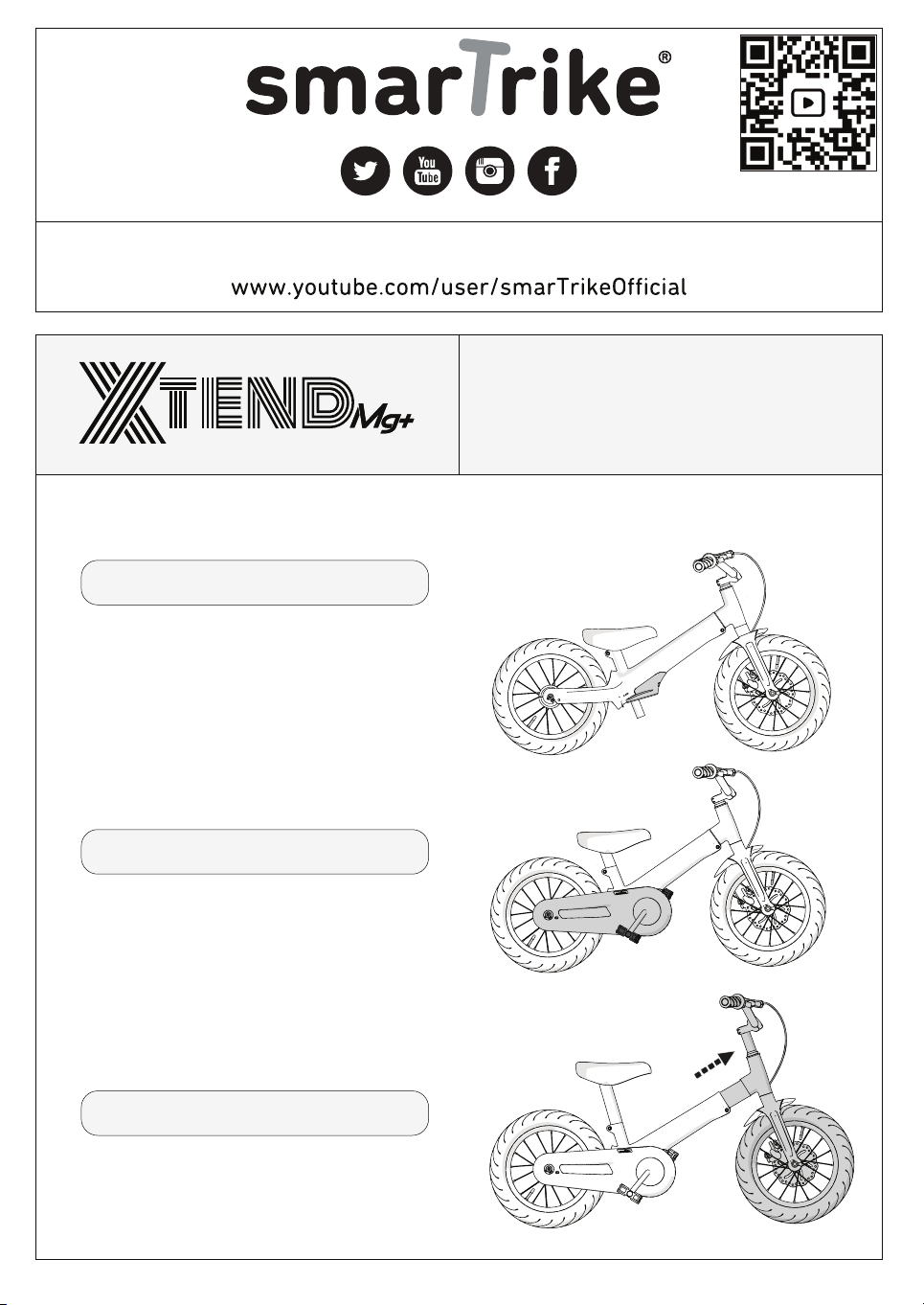
Balance
Pedal
Teach them to ride
watch them go...
Bike
See them fly!
20601A
Max load 50kg/110lbs
Ages 3-6yrs
Designed to fit riders with measurements
Inseam: 40-59cm/15.6-23inch
Height: 95-125cm/37-49inch.
™

-2-
Assembly parts
1
L
R
6mm / 0.23’’
5mm / 0.2’’
2
Australia BEB1501
17mm / 0.7''
15mm / 0.6''
USA/Canada BEB1502 BEB1001
BEB1002
BEB1011201 BEB1509101 / BEB1020201
BEB1008104
BEB1508101
BEB1512201
BEB1025201 BEB1026201 BEB1027201
BEB1013201 BEB1004102
BEB1024201
NOTE: This information is only available on the bicycle itself.
Each bicycle has a Recovery Code stamped into the frame. The Recovery Code
.can be found on the bottom of the crank housing as shown
X
X
X
X
X
X
X
X
X
X
X
XX
-3-
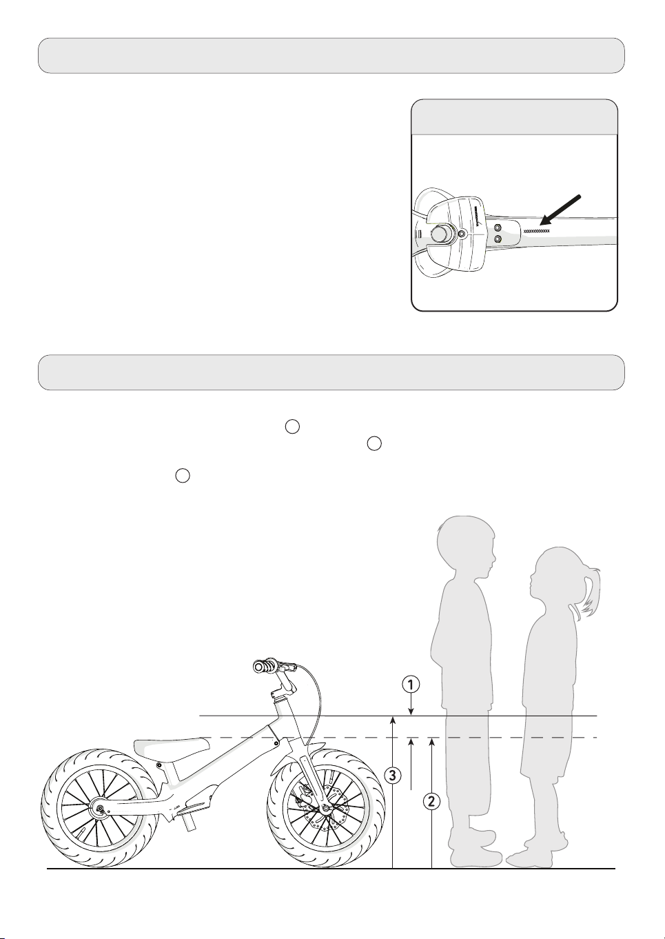
Under the body tube
NOTE: This information is available only on the bicycle.
As shown in the image, our bicycle has the production date
code stamped into its body (model / STB / month / year)
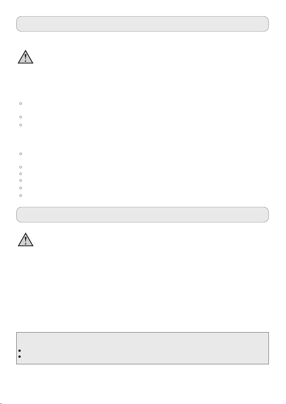
3 Steps to Adjust the Bike to the Rider
Owner’s Bicycle Identification Record
1.
2.
3.
Assemble the bike. Make sure the tyres are well inflated.
Riders must have at least 1inch/2.5cm 1 between their crotch and the seat when standing
with feet shoulder-width apart and flat on the ground
Make necessary adjustments to the bike so the rider’s leg-length is at least 2.5cm/1” higher
than the bike's seat 3 .
2 .
-4-
The Owner’s Responsibility
Warning and Safety Information
Meanings of Warnings:
As small parts exist, a CHOKING HAZARD exists. Not recommended for small children.
under 3 years.
Adults need to assemble the bicycle.
The replacement of the handlebar hand grip or tube end plugs must be done if it is
damaged. This is necessary as bare tubes could cause injury. All the products with
capped handlebar ends need to be regularly checked to ensure that there is ample
protection for the ends of the handlebars.
The replacement forks should have the same rake and tube inner diameter just like the
original product.
No motor should be added to the product.
The product should not be towed or pushed.
No modification should be made to the product.
Any worn or broken parts must be replaced immediately.
Discontinue use if any part does not function properly.
WARNING: Only one rider must ride this bicycle at a time for general transportation and
recreational purpose. It has not been designed to withstand the abuse of jumping or stunting.
NOTE: Frequently check that all the components and fasteners are properly tightened.
In case the bicycle was purchased in an assembled state, it is the owner’s responsibility, before
riding it for the first time, to ensure it has been assembled and adjusted exactly as written in this
manual, and any “Special Instructions” provided and to ensure all components and fasteners are
properly tightened.
The bicycle was unassembled while purchasing, it is the responsibility of the owner to follow all the
assembly and adjustment instructions carefully just as they are written in this manual. Take care of
any “Special Instructions” that have been supplied and ensure that all the components and fasten-
ers are properly tightened.
NOTE:
If the product is assembled, please proceed to these sections:
Testing Stem and Handlebar Tightness.
Testing the seat- Post Clamp Tightness.
This symbol is highly crucial. Carefully see the word “CAUTION” or “WARNING” which follows
it. The word “CAUTION” is provided before mechanical instructions. In case you do not obey these
instructions carefully, mechanical damage or failure of a part of the bicycle can take place.
The word “WARNING” is given before personal safety instructions. If you do not obey these
sensitive instructions, injury to the person riding or to others can take place.
NOTE: This information is only available on the bicycle itself.
Each bicycle has a Recovery Code stamped into the frame. The Recovery Code
.can be found on the bottom of the crank housing as shown
-5-
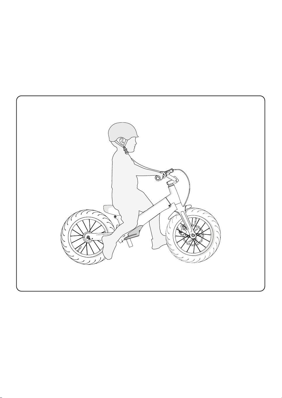
Rules of the Road
WARNING:
from injury or others could be hurt.
You must wear a bicycle helmet that meets the local standard and the local safety
standards.
Make sure to wear shoes while riding.
Ride on the correct side of the road, in a straight line and in a single file.
Bikes not intended for use on the public roads.
Avoid riding the bike at night, dusk, dawn and any other time when the visibility is
poor.
Reflectors: Do not ride the bicycle in case the reflectors are not installed correctly,
damaged, or missing, for your own safety. Ensure the front and rear reflectors are
vertical. Make sure that the visibility of the reflectors is not blocked by clothing or
other articles. Clean the reflectors as necessary with soap and a damp cloth
because dirty reflectors do not work well.
Use extra caution in wet weather:
Ride the bike slowly on damp surfaces as the tyres could slide easily.
Allow increased braking distance while riding in wet weather.
Avoid these hazards to prevent loss of control or damage to your wheels:
Be careful of drain grates, soft road edges, sand or gravel, potholes or ruts, wet
leaves, or uneven paving.
Make sure to cross railroad tracks at a proper angle to prevent losing control of
the bike.
Unsafe actions must not be conducted while riding.
Passengers must not be carried while riding the bicycle.
Do not carry any items or attach other things to your bicycle that could obstruct
your vision, hearing or control.
Do not fit a luggage carrier and (or) a child seat to the bicycle.

-6-
Assembly parts
NOTE: All features, components
and accessories are not included
on all models.
NOTE: This information is only available on the bicycle itself.
Each bicycle has a Recovery Code stamped into the frame. The Recovery Code
.can be found on the bottom of the crank housing as shown
1
2
4
6
7
8
8
10 11
20
21
14
15
16
16
15
17
18
13
12
19
23
24
25
22
26
26
26
26
3
27
5
9

-7-
Fitting the
Assembly
No.No.
1
Description
Frame
2Fork
3Handlebar
4Grips (x2)
5Handlebar Stem
6Seat
7Seat Post
8Clamp
9Head Set Bearings
10 Right Pedal
20 Chain
21 Chain Cover
Balance Bike System
22
23
25
26
24
Bell
Reflectors
27 Coaster Brake
11 Left Pedal
12
Description
Wheel Retainer (x2)
Balance Bike System Bolts (x3)
13 Front Wheel Nut (x2)
15 Tyre (x2)
16 Tube (x2)
14 Front Wheel Assembly
17 Rear Wheel Assembly
18 Front brake disc
19 Hand Brake
Follow all the instructions completely and carefully.
Please read the entire manual through before starting
assembly or maintenance.
In case you are not confident with assembling this unit,
please refer to a local bike shop.
Parts Assembly List
Back Wheel Nut (x2)
WARNING: Keep small components away from children during the assembly
process.
NOTE: All of the directions (right, left, front, rear, etc.) provided in this
manual are as seen by the rider riding the bicycle.
Do not dispose of the carton or other packaging parts until the assembly of
the bicycle is complete. It can prevent accidentally discarding components
of the bicycle.

Installing the Front Part
1. Release the screw and
nut.
2. Insert the front complex
into the body.
3. Tighten the screw
and the nut.
1
3
-8-
2
3
1

5mm / 0.2‘’
5mm / 0.2‘’
4
-9-
5a
5b
A
B
4. Unfasten the 4 stem screws.
5a. Place the handlebar on the head tube.
5b. Reattach the stem and fasten the screws.
Handlebar and Stem Installation

2
fig B
1
F
3
F
If necessary, make the the handlebar clamp nut/screw F loose and rotate the handlebar into
a comfortable riding position (fig A, B).
-10-
Handlebar and Stem Installation
Adjusting the handlebar
WARNING: In order to prevent any steering system
damage and possible loss of control,, the “MIN-IN”
(minimum insertion) mark , on the stem must be
below the top of the locknut B .
NOTE:
Separate the plastic cap C from the end of the stem
D .
A
STEPS:
1. Insert the stem D into the fork (fig A).
2. Point the stem towards the the front section of
the bike.
3. Streamline the stem with the front tyre and
tighten the stem bolt securely.
4. Tighten the stem bolt E just enough to hold it
in place.
WARNING: If the handlebar clamp in not tight enough, the handlebar can slip in the stem. This
can cause damage to the handlebar or stem, and can cause loss of control.
NOTE: Do not over tighten. See torque
table for recommended torque.
D
E
A
B
C
fig A
6mm / 0.23‘’
5mm / 0.2‘’ 5mm / 0.2‘’
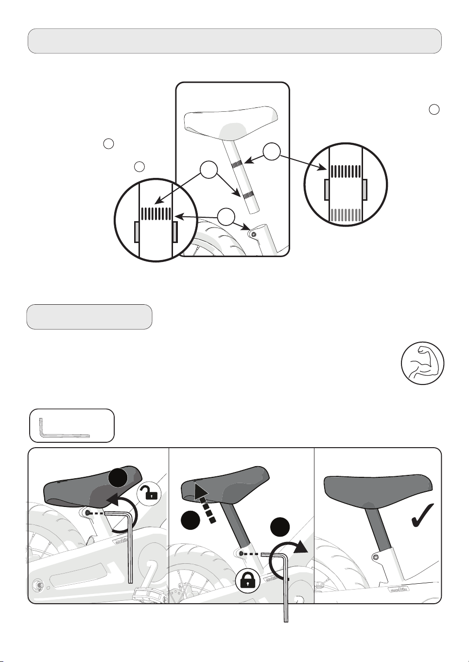
-11-
Use a 5mm/0.2'' Allen key for adjusting the height of the
seat as per the drawing on page number 3.
Pull the seat out as per the required height.
Use the 5mm/0.2” Allen key for locking the mechanism back.
A
BC
After assembling the seat,
press down on the seat to
make sure it is well
reinforced.
C.
B.
A.
Seat Bolt Mount
Seat Installation
WARNING: In order to
prevent the seat from
becoming loose and a
possible loss of control, the
“MIN-IN” (minimum
insertion) mark A on the
seat post is placed below
the top of the seat tube B .
A
B
C
According to European standards,
do not insert the seat further than
the top mark (Illustration mark C ).
5mm / 0.2‘’

-12-
Testing Stem and Handlebar Tightness
To test the tightness of the stem:
Straddle the front wheel of the bike between your legs.
Turn the handlebar in order to try and turn the front wheel.
If the stem and handlebar turn without turning the front wheel, readjust the stem with the
wheel and secure the stem bolt(s) tighter than before (about 1/2 revolution only at a time).
Carry out this test again, until the stem and handlebar do not turn without turning the
front wheel.
To test the tightness of the handlebar clamp:
Hold the bicycle in a stable way and try to move the ends
of the handlebar forward and backword or up and down.
WARNING: Make sure not to exceed 100 lbs (45 kg)
force.
If the handlebar moves, loose the
bolt(s) of the handlebar clamp loosen.
Place the handlebar in the proper
position and tighten the bolt(s) of the
handlebar clamp tighter than before.
Carry out this test again, until the
handlebar does not move in the
handlebar clamp.

1
2 3
5mm/0.2’’
To adjust the front brake – please follow these illustrations:
-13-

-14-
Assembly
Step 1:
Turn the bicycle in an upside down manner so the rear wheel is upwards.
C
B
A
2
Step 2:
5mm / 0.2‘’
Attach the footrest to the bottom of the frame
using 5mm /5” Allen key and 3 bolts.
+
1
-15-
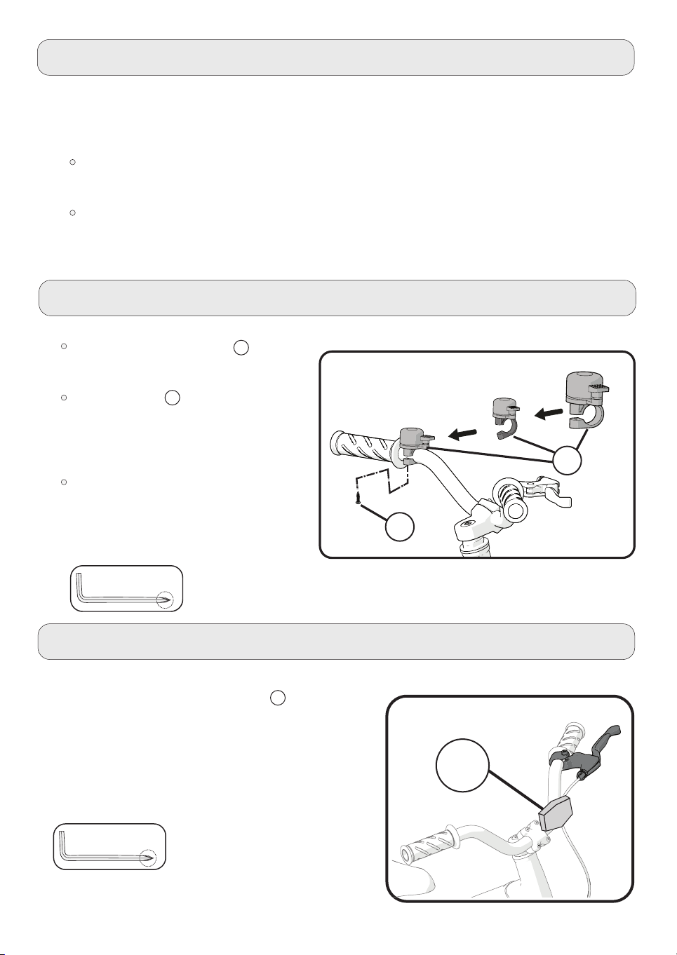
Bell Feature
In case the mounting screw A is
factory installed remove it and set it
aside.
Open the clamp B just enough so that
the handlebar can be fit on.
Position the bell / accessory so that it
can be in proper level and position as
shown.
Tighten the screw securely. Be careful
not to over tighten it as this could
damage the clamp.
B
A
Reflector Installation
Reflector Installation:
1. Position the FRONT white reflector A so that it points
in a straight forward manner.
2. Tighten the clamp screw carefully.
NOTE: Do not over-tighten as this would damage the
clamp.
Testing The Seat - Post Clamp Tightness
To test the tightness of the seat-post clamp:
Try turning the seat side-to-side.
If the Seat Post moves in the seat tube:
Tighten the Allen screw which is on the seat-post clamp.
Repeat this test again, until the seat post does not move in the seat tube.
6mm / 0.23‘’
6mm / 0.23‘’
A
-16-
-17-
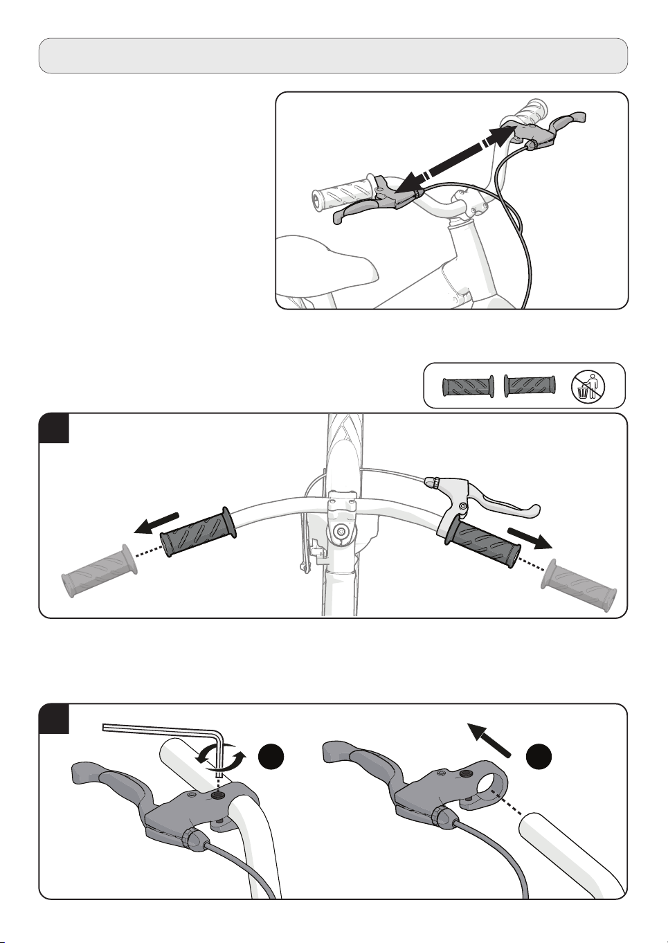
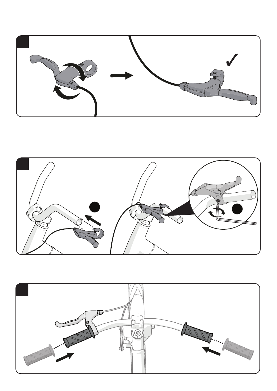
Change brake leaver side
To switch the brake from the right to the
left side, according to the US standard,
follow the instructions below:
Remove the handle grips from both sides, and keep it aside.
A. Use the 5 mm / 0.2” Allen key to loosen the screw slightly.
B. Remove the brake leaver from the handlebar handle.
Step 1:
Step 2:
1
2
BA
-18-
Turn the brake leaver over.
Step 3:
A. Insert the brake leaver on the left handlebar.
B. Lock and tighten the screw with the 5 mm / 0.2” Allen key.
Step 4:
Reattach the handlebar grips.
Step 5:
3
4
B
A
5

-19-
-20-
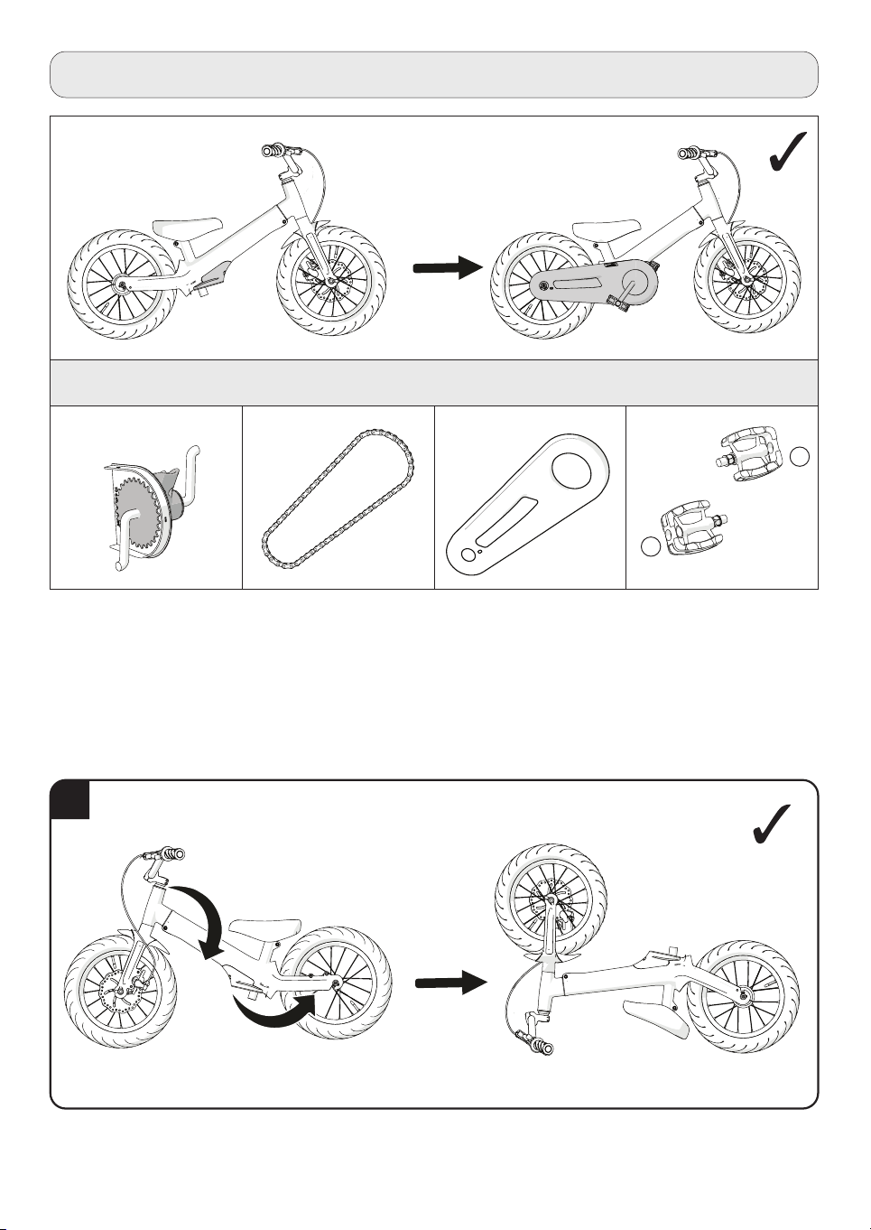
Turn the bicycle in an upside down manner so the front wheel is upwards.
Step 1:
Balance bike mode to pedal mode
Assembly parts
L
R
- No need to remove the wheels -
1
Table of contents
Other SmarTrike Bicycle manuals

SmarTrike
SmarTrike 820 User manual

SmarTrike
SmarTrike 607 User manual

SmarTrike
SmarTrike Vanilla Plus 665 User manual

SmarTrike
SmarTrike 502 User manual

SmarTrike
SmarTrike Breeze 605 User manual

SmarTrike
SmarTrike Delight User manual

SmarTrike
SmarTrike 680 User manual

SmarTrike
SmarTrike Xtend Bike Guide

SmarTrike
SmarTrike 650 User manual

SmarTrike
SmarTrike Cruise 620 User manual


