SmartSafe CAT-601S User manual


CAT-601S Auto Transmission Cleaner and Fluid Exchanger User’s Manual
ii
Trademark Information
is a registered trademark of
SHENZHEN SMARTSAFE TECH. CO., LTD.
(SMARTSAFE for short) in China and other countries.
All other SMARTSAFE trademarks, service marks,
domain names, logos, and company names referred to
in this manual are either trademarks, registered
trademarks, service marks, domain names, logos,
company names of or are otherwise the property of
SMARTSAFE or its affiliates. In countries where any of
the SMARTSAFE trademarks, service marks, domain
names, logos and company names are not registered,
SMARTSAFE claims other rights associated with
unregistered trademarks, service marks, domain names,
logos, and company names. Other products or company
names referred to in this manual may be trademarks of
their respective owners. You may not use any trademark,
service mark, domain name, logo, or company name of
SMARTSAFE or any third party without permission from
the owner of the applicable trademark, service mark,
domain name, logo, or company name. You may contact
SMARTSAFE by visiting SmartSafe at http://
www.newsmartsafe.com, or writing to 3F, Building B,
Qiao'an Technology Industrial Park, Guanlan, Longhua
New District, Shenzhen, Guangdong, P. R. China, to
request written permission to use Materials on this
manual for purposes or for all other questions relating to
this manual.
Copyright Information
Copyright © 2021 by SHENZHEN SMARTSAFE TECH.
CO., LTD. All rights reserved. No part of this publication
may be reproduced, stored in a retrieval system, or
transmitted in any form or by any means, electronic,
mechanical, photocopying, recording or otherwise,
without the prior written permission of SMARTSAFE.
The information contained herein is designed only for
the use of this unit. SMARTSAFE is not responsible for
any use of this information as applied to other units.
Neither SMARTSAFE nor its affiliates shall be liable to
the purchaser of this unit or third parties for damages,
losses, costs, or expenses incurred by purchaser or
third parties as a result of: accident, misuse, or abuse of
this unit, or unauthorized modifications, repairs, or
alterations to this unit, or failure to strictly comply with
SMARTSAFE operating and maintenance instructions.
SMARTSAFE shall not be liable for any damages or
problems arising from the use of any options or any
consumable products other than those designated as
Original SMARTSAFE Products or SMARTSAFE
Approved Products by SMARTSAFE.
General Notice
Other product names used herein are for identification
purposes only and may be trademarks of their
respective owners. SMARTSAFE disclaims any and all
rights in those marks.

CAT-601S Auto Transmission Cleaner and Fluid Exchanger User’s Manual
iii
The equipment is for specialist or qualified
technician use only.
Disclaimer
All information, illustrations, and specifications
contained in this manual are based on the latest
information available at the time of publication.
SmartSafe reserves all the rights to make changes at
any time without notice.
Safety Precautions
Read all service procedures and precautions, installation
instructions and equipment operating manuals thoroughly.
Failure to observe these precautions, or the improper use of
equipment, could result in property damage, serious injury
or death. Never allow improperly trained personnel to
perform these procedures or operate equipment.
Read and understand the User’s Manual before
attempting to operate the CAT-601S.
Do not smoke in proximity to the machine while it is in
operation.
Do not use the machine in proximity to sources of heat
and fire.
Do not expose to direct sunlight or rain, use in
well-ventilated work area only.
Turn off the power after the operation is completed.
When it is in operation, keep the hoses away from
rotating elements and hot parts such as cooling fans,
radiators, etc.
Vehicle exhaust includes various poisonous and
harmful gases (such as carbon monoxide,
hydrocarbon, nitrogen oxygen complex, etc.). Keep the
unit in a well ventilated work area when performing
operation and wear safety goggles, respirator and
clothes.
The operator should keep away from the heat parts
such as exhaust hoses and radiator to avoid the
personal injury.
When disconnecting any connector of the pressurized
fluid pipe, wrap the connector with towel to prevent the
fluid from spurting out.
The children and mental retardation personnel should
keep away from the unit during operation.
The operator should be quite familiar with the shift of
automatic transmission to avoid transmission damage
caused by improper operation.
Always make the drive wheels hanging when cleaning
the transmission or exchanging fluid.
The unit should be placed vertically and should not be
placed upside down.
When changing fluid, the operation should be
performed by properly trained personnel. The quality of
the selected ATF must conform to the direction as
specified in the manual of the auto to be operated.
Otherwise, SMARTSAFE shall not be liable for any
direct or consequential damages.
Note: specifying operations that require
attention when operating the equipment.
Warning: Specifying a possible hazard that
could result in damage to the machine or personal
injury.
FCC Warning
Any Changes or modifications not expressly approved
by the party responsible for compliance could void the
user's authority to operate the equipment.
This device complies with part 15 of the FCC Rules.
Operation is subject to the following two conditions: (1)
This device may not cause harmful interference, and
(2) this device must accept any interference received,
including interference that may cause undesired
operation.
This equipment has been tested and found to comply
with the limits for a Class B digital device, pursuant to
part 15 of the FCC Rules. These limits are designed to
provide reasonable protection against harmful
interference in a residential installation. This
equipment generates, uses and can radiate radio
frequency energy and, if not installed and used in
accordance with the instructions, may cause harmful
interference to radio communications. However, there
is no guarantee that interference will not occur in a
particular installation. If this equipment does cause
harmful interference to radio or television reception,
which can be determined by turning the equipment off
and on, the user is encouraged to try to correct the
interference by one or more of the following measures:
—Reorient or relocate the receiving antenna.
—Increase the separation between the equipment and
receiver.
—Connect the equipment into an outlet on a circuit
different from that to which the receiver is connected.
—Consult the dealer or an experienced radio/TV
technician for help.
This equipment complies with FCC radiation exposure
limits set forth for an uncontrolled environment .This
equipment should be installed and operated with
minimum distance 20cm between the radiator& your
body.

CAT-601S Auto Transmission Cleaner and Fluid Exchanger User’s Manual
1
Table of Contents
Introduction......................................................................................................................................................................2
Features..........................................................................................................................................................................2
Working Conditions.......................................................................................................................................................... 2
Specifications.................................................................................................................................................................. 2
Structure......................................................................................................................................................................... 2
1. Outline.....................................................................................................................................................................2
2. Overall structure.......................................................................................................................................................3
3. Pipeline diagram...................................................................................................................................................... 4
4. Circuit connection diagram........................................................................................................................................4
5. Control panel........................................................................................................................................................... 5
Operations.......................................................................................................................................................................6
1. Preparation.............................................................................................................................................................. 6
1.1 Jack vehicle....................................................................................................................................................... 6
1.2 Connecting hose................................................................................................................................................ 6
1.3 Power cables connection.................................................................................................................................... 7
1.4 Check-up........................................................................................................................................................... 7
2. Old oil sampling........................................................................................................................................................7
3. Filling liquid..............................................................................................................................................................8
3.1 Filling detergent..................................................................................................................................................8
3.2 Adding new oil.................................................................................................................................................... 8
4. Circulating cleaning.................................................................................................................................................. 8
3.1 Fill detergent to auto transmission........................................................................................................................8
3.2 Circulating cleaning............................................................................................................................................ 8
3.3 Finish circulating cleaning................................................................................................................................... 8
5. ATF exchange..........................................................................................................................................................8
5.1 Direct Input........................................................................................................................................................ 9
5.2 Vehicle Selection OK.......................................................................................................................................... 9
6. Adjusting fluid level................................................................................................................................................. 10
6.1 Increase fluid amount........................................................................................................................................10
6.2 Decrease fluid amount.......................................................................................................................................11
7. Empty new fluid tank...............................................................................................................................................11
8. Empty used fluid tank..............................................................................................................................................11
9. System setting........................................................................................................................................................11
9.1 Sensor calibration.............................................................................................................................................12
9.2 Select transmission fluid....................................................................................................................................13
9.3 Window Light Switch Setting..............................................................................................................................13
9.4 LCD Screen Brightness Adjustment....................................................................................................................14
9.5 Date & Time..................................................................................................................................................... 14
9.6 Language setting.............................................................................................................................................. 14
9.7 Vehicle Adding..................................................................................................................................................15
9.8 Print Setting..................................................................................................................................................... 15
9.9 History Records................................................................................................................................................16
9.10 Device information.......................................................................................................................................... 16
Warning.........................................................................................................................................................................16
Maintenance..................................................................................................................................................................16
Main adapters............................................................................................................................................................17

CAT-601S Auto Transmission Cleaner and Fluid Exchanger User’s Manual
2
Introduction
The transmission fluid inside transmission will go bad
after a period of usage of automatic transmission. If the
transmission fluid cannot be changed completely in time,
it may cause the abnormality to the transmission.
Generally speaking, Auto Transmission Cleaner and
Fluid Exchanger cannot control the filling quantity of the
ATF as required, the excessive or shortage filling will
cause the damage to auto transmission. CAT-601S auto
transmission cleaner and fluid exchanger can complete
the flush and fluid exchange in 20 minutes for
transmission, torque converter and radiator. The fluid
exchange rate is nearly 100%.
Features
LCD display and personalized design making easy
operation.
Multi-language print.
Filling and recycling of automatic transmission fluid.
Automatic identification for the fluid flow inlet/outlet
direction.
Circulating cleaning for automatic transmission.
Easy for detergent filling.
Automatic exchange of new/used fluid.
Visual display of the fluid pressures.
Accurate display of the automatic transmission fluid
temperature.
Intelligent electronic control for the full automatic
equivalent exchange of new and used fluid.
Manually adding and upgrading database function.
Various special adapters are applicable to vehicle
types made in Europe, America and Asia.
Effectively resolve the incomplete fluid exchange of
manual operation.
It improves the working performance of auto
transmission.
It prolongs the work life of transmission.
Working Conditions
Ambient temperature: -10~+50°C
Relative humidity: <90%
Specifications
Power supply: 110V-127V~,50Hz/60Hz
Maximum power: 150W
Pressure gauge: 0~150psi
Fluid outlet hose: 2.5 m
Fluid return hose: 2.5 m
Fluid draining hose: 1.2 m
Filter precision: 5µm
Filter life span: about one year if using one time a
day
Fluid tank: 20L×2
Equivalent exchange error: ±100ml
Mean exchange speed: 2L/MIN
Noise: <70db
Size: 588x672x1024mm
Structure
1. Outline
As shown in Fig.1, CAT-601S is designed with a fine
cabinet. There is a handle at the top of cabinet and two
pairs of casters at the bottom of the cabinet, which
makes it easy to move the unit. Fluid hoses are
equipped with proper connectors for fast connection.
The intelligible control panel helps you operate the
machine easily.
Fig.1
1- Sight indicator of used fluid; 2- Sight indicator of new fluid; 3- Power plug hole; 4- Power switch; 5- Operation screen;
6- Fluid filling port; 7- Fluid draining hose; 8,9- Hoses; 10-Printer; 11-Detergent container; 12-filter.;13-tablet stora box.
CAT-601S Auto Transmission Cleaner and Fluid Exchanger User’s Manual
3
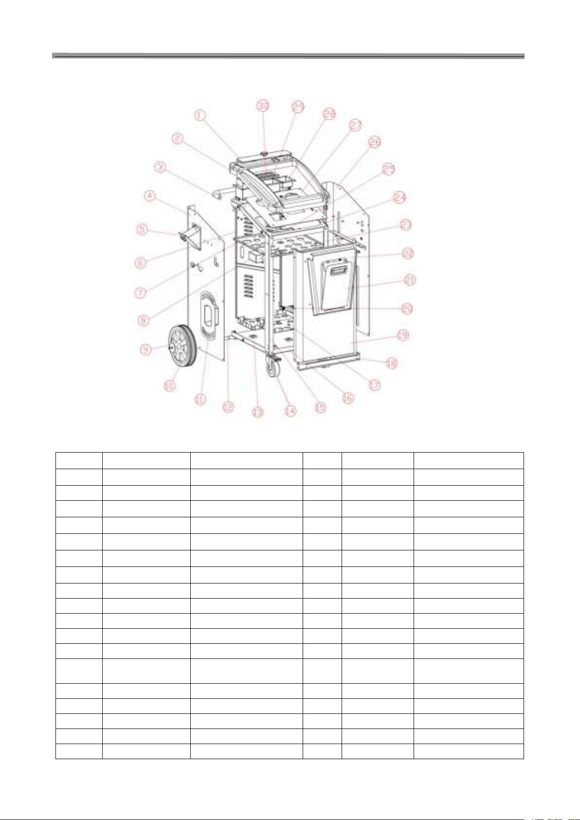
2. Overall structure
Fig.2
SN ERP Code Name SN ERP Code Name
1 501020022 Oil sump cover 19 501020005 Front board
2 504010074 Blister top cover 20 501020026 Door hinge
3 501020017 Handle 21 501020007 Tablet storage box
4 501020003 Right side board 22 501020006 Front decorative panel
5 501020027 Fuel hopper 23 501020008 Left column
6 501020014 Back door 24 501020010 Roof
7 501020012 Partition plate 25 501020013 Bottle clip
8 501020028 Socket guard 26 501020004 Left side board
9 501020023 Rear wheel cover 27 501020015 Operation Panel
10 Rear wheel 28 501020021 Cleaning liquid tank
11 501020020 Around the tube rack 29 501020011 Sump
12 501020019 Rear axle 30 501020016 Oil filter plate
13 503200007 Electronic weighing pan
plate
14 Front wheel
15 501020009 Right upright
16 501020001 Bottom plate
17 501020025 Oil drum tray
18 501020018 Front and bottom rails

CAT-601S Auto Transmission Cleaner and Fluid Exchanger User’s Manual
4
3. Pipeline diagram
The pipeline diagram is as shown in Fig.3.
Fig.3
1-Pump; 2,3,15,23-Three-way solenoid valves; 4-Fluid filling port; 5-New fluid tank; 6,8-Electronic scales; 7-Detergent
container; 9- Used fluid tank; 10,17-Filters; 11- Fluid path identifier; 12,18- Pressure gauges 13,14- Sight indicators;
16-Two-way solenoid valve; 19- Check valve; 20- Ball valve for fluid draining; 21- Temperature sensor; 22- Old oil sampling
valve.
4. Circuit connection diagram
The circuit connection diagram is as shown in Fig.4.
Fig.4
J8 To solenoid V2 J25 To unit serial port cable
J12 To solenoid V1 J14 To temperature sensor
J17 To solenoid V3 J15 To used fluid tank sensor
J22 To solenoid V4 J16 To new fluid tank sensor
J78 To solenoid V5 ATN1 To Bluetooth antenna
J21 To oil pump J13
To key-press film
J24
To switch power supply
J33
To VGA display and drive module
J26
To printer power supply
J3
Test port, used by SMARTSAFE only
J23 To printer data cable J4 To sight indicators for used & new fluid

CAT-601S Auto Transmission Cleaner and Fluid Exchanger User’s Manual
5
5. Control panel
The control panel is as shown in Fig.5.
Fig.5
Description:
Element Description
NEW Observe the flow rate and compare the color of new and used fluid. Display the
fluid outlet pressure. Display the fluid pressure of AT radiator.
USED
Press it to select function option in main menu.
Press it to select function option in main menu.
OK Confirmation.
1. Menu to return.
2. Press one time to stop current operation, and press once more to return to
previous interface.
DEL Press to delete the previous character in focused window, and in database
interface, press it you can delete some menu item.
1. In main-menu, you can switch on/off the lights of sight indicators.
2. In focused window, press it you can OK the character of “.”.
3. When OKing some menu option on database interface, press it you can
switch between uppercase and lowercase letters.
0(A、B、C)
1(D、E、F)
2(G、H、I)
3(J、K、L)
4(*)
5(M、N、O、P)
6(Q、R、S)
7(T、U、V)
8(W、X、Y、Z)
9(#)
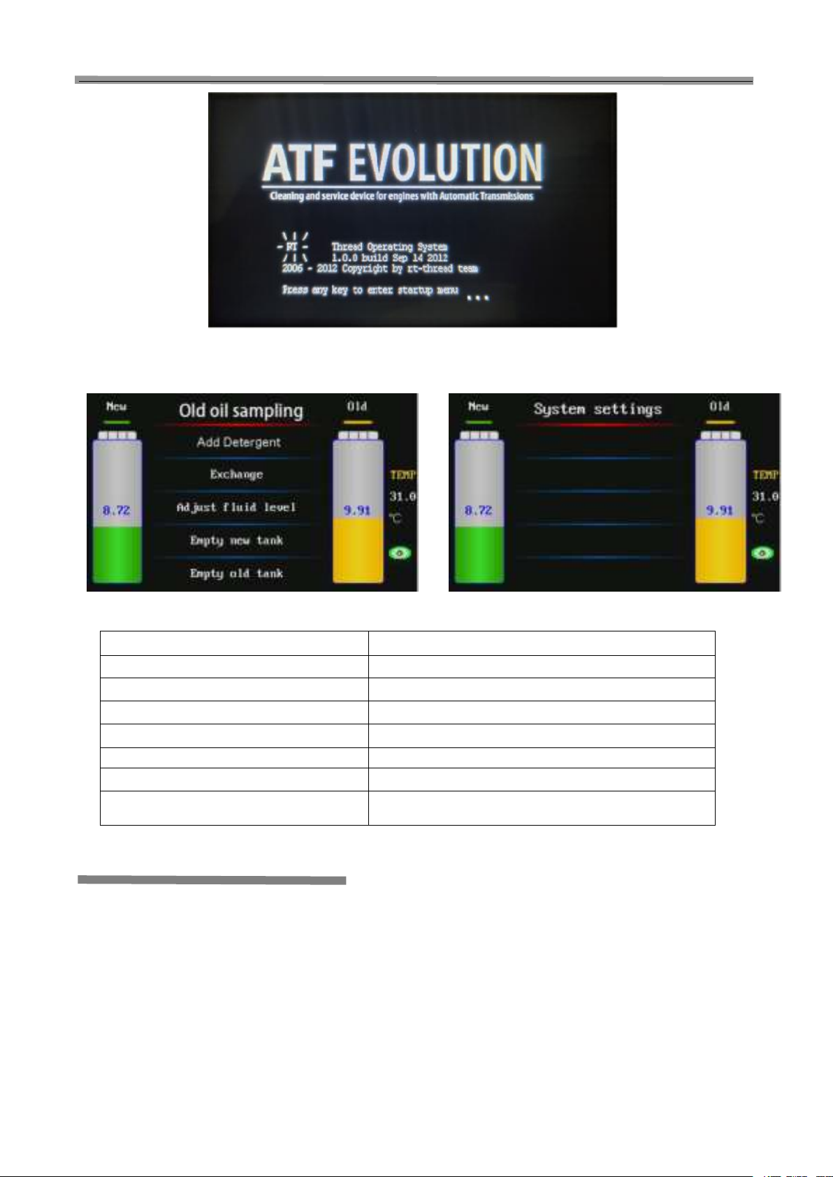
1. Startup interface: (As shown in Fig.6)
In the startup interface press any key to OK the upgrade multilingual document interface.
CAT-601S Auto Transmission Cleaner and Fluid Exchanger User’s Manual
6
Fig.6
2. The main menu of display screen is as shown in Fig.7.
Fig.7
Item Description
Old oil sampling Sampling the oil from AT
Add detergent Add ATF detergent to AT
Exchange Exchanging ATF
Adjust fluid level Adjusting the quantity of fluid inside AT
Empty new tank Draining left fluid inside new fluid tank
Empty used tank Draining used fluid inside used fluid tank
System setting Modifying the system parameter, e.g.: Calibration of electronic
scale, adjusting contrast, language selection, database entry.
Operations
Note:
During the unit is in operation, it will produce the
vibration with a certain frequency and noise. This is
the normal performance. Do not take it as the
malfunction. 1. Preparation
1.1 Jack vehicle
Jack the vehicle to keep the drive wheel off the ground
at least 200mm, apply the parking brake and block the
driven wheels in front and behind.
1.2 Connecting hose
1) Locate the fluid hose that is connected between the
radiator and transmission at the most convenient
location and then disconnect the adaptor. Locate the
matched connector inside the connector box and
connect it to the disconnected adapter.
2) Connect the two hoses marked “TO
TRANSMISSION” of CAT-601S to the disconnected
two ends of the hoses of automatic transmission (no
necessary to consider the direction of the fluid flow).
Refer to Fig.7.

CAT-601S Auto Transmission Cleaner and Fluid Exchanger User’s Manual
7
1.3 Power cables connection
Connect the power cables of the main unit to the
designed power supply.
1.4 Check-up
1) Start the engine, and ensure that there is no
leakage in pipeline.
2) Confirm that the power supply of the CAT-601S is
normal, and then switch on the unit.
Fig.8
2. Old oil sampling
Preparation: please connect the inlet-outlet oil pipe of
device with vehicle transmission, and prepare the bottle
for sampling, open the valve of old oil samplingor
manually open the valve on the 10-second countdown
interface;
1) Click 'Old oil sampling', and enter old oil sampling,
currently the default countdown is 10 seconds;
2) It prompts whether to perform old oil sampling or not.
Press OK to continue, or press RETURN to cancel;
3) Press OK to enter the 10-second countdown interface
of old oil sampling. Press OK to pause, or press
RETURN to exit sampling;
Fig.9
CAT-601S Auto Transmission Cleaner and Fluid Exchanger User’s Manual
8
3. Filling liquid
3.1 Filling detergent
When you are ready to perform the circulating cleaning
for auto transmission, please fill proper amount of
detergent into the detergent container (please refer to
Fig.3).
3.2 Adding new oil
When you are ready to perform the ATF exchange
operation, please fill new fluid into the new fluid tank
from the fluid filling port (please refer to Fig.3).
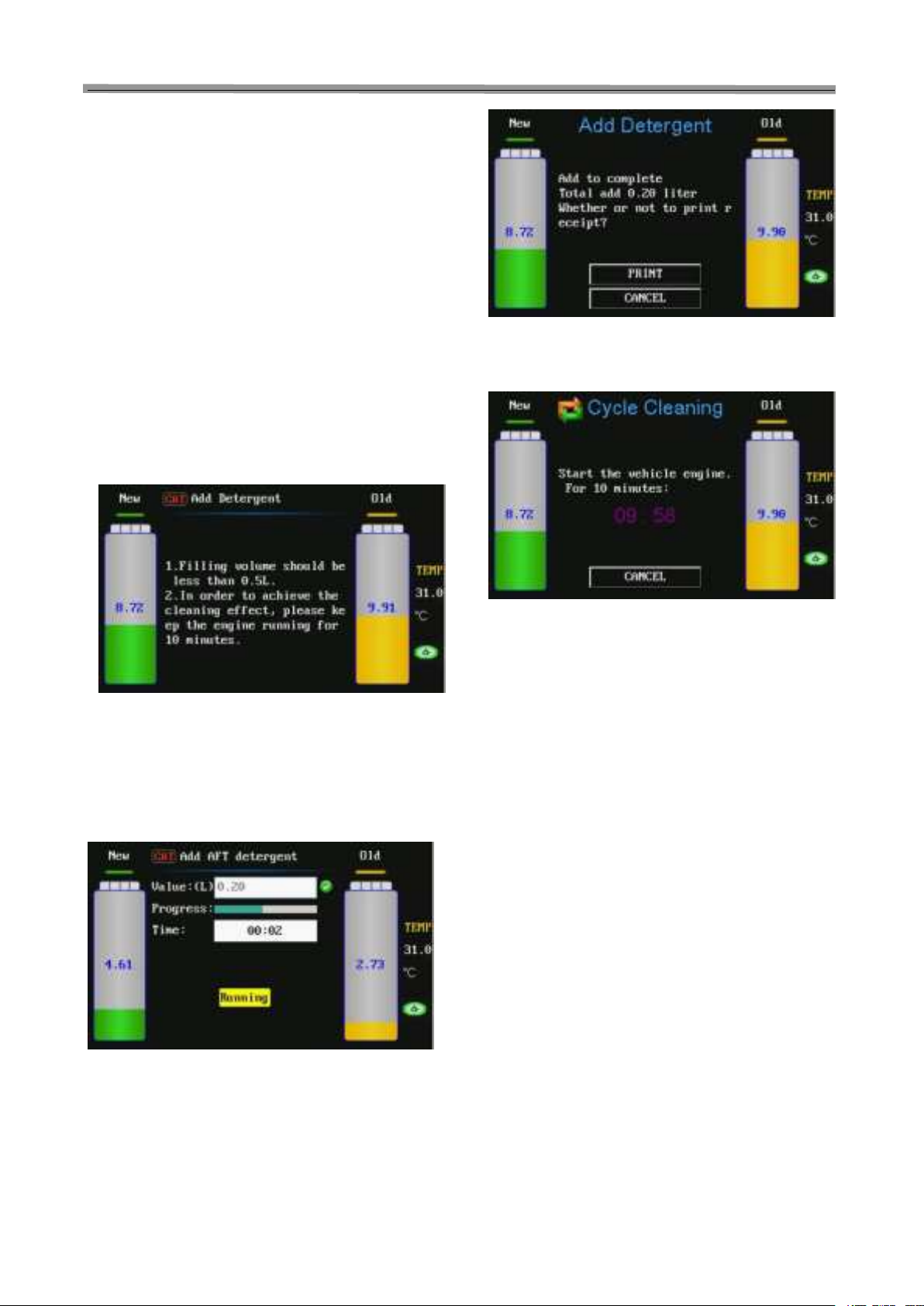
4. Circulating cleaning
4.1Fill detergent to auto transmission
1) Select the function of “Add ATF detergent” in main
menu, and set the amount of the detergent to be filled
(the setting range: 0.00-0.50 L). Refer to Fig.10.
Fig.10
Note: Fill detergent before need to calibrate cleaning
speed (see "cleaning speed" sensor calibration content).
2) Input the amount to be filled. The default value of the
unit is 0.20L and the maximum value is 0.50L. Press
OK key after the amount to be filled is confirmed, the
detergent filled inside the detergent container will be
pumped into the hose.
Fig.11
3) After the filling operation is finished, the system will
automatically pop up print menu. Press OK key select
print, press RETURN key to cancel printing. Refer to
Fig.12
Fig.12
4) Print is completed or cancelled, will pop up 10
minutes cycle cleaning countdown. Refer to Fig.13.
Fig.13
4.2 Circulating cleaning
After the detergent is filled into the hose, start the
engine and the fluid will circulate from the CAT-601S
pipelines to the Automatic Transmission. In order to
speed up the circulating process, it is advisable to
perform the gear-shift operation (The running time for
each gear-shift should be kept for about 1 minute,
which depends on actual situation. When the vehicle
engine is running with high-speed, the speed should be
more than 60 km/h to ensure the effect of cleaning).
The circulating cleaning option is not set in CAT-601S
main menu. When the hoses are well connected, start
the vehicle engine and the unit will OK the circulating
process automatically. If the cleaning circulation
operation is needed for a long period of time, please
turn off the power supply of CAT-601S.
4.3 Finish circulating cleaning
After the circulating cleaning operation has been lasted
for more than 10 minutes, please turn off the engine to
end the circulating cleaning process.
5. ATF exchange
When different kind of fluid is used or the unit is stored
for a long time, about 0.5L new fluid should be filled into
new fluid tank. With the way of emptying the new fluid
tank, clean the fluid hoses and drain the air bubbles out
from the unit.

CAT-601S Auto Transmission Cleaner and Fluid Exchanger User’s Manual
9
1)Start the vehicle to warm up the fluid inside the
transmission to normal temperature and fill the new
transmission fluid with desired amount into it.
2)Check if the pipelines are well connected.
3)ATF exchange: as shown in Fig.14, you can
directly input the fluid amount to be changed, as
well as you can obtain the amount by selecting
Vehicle Selection option.
Fig.14
5.1 Direct Input
Select Direct Input, and press OK key to OK into the next
interface, and then input the fluid amount to be changed
(the default value is 10L), as shown in Fig.15.
Fig.15
Be sure that there is no leak in the pipelines and press
OK key to exchange, as shown in Fig.16.
Fig.16
After the exchange operation is finished, the system will
automatically pop up print menu. Press OK key select
print, press RETURN key to cancel printing. Refer to
Fig.17
Fig.17
Print is completed, the system will return to the interface
as shown in Fig.14.
5.2 Vehicle Selection OK
Select Vehicle Selection option, and press OK key you
can see the vehicle model menu as shown in Fig.18.
Fig.18
Select the menu path of the specific vehicle model to OK
the testing interface which displays the fluid amount to be
changed, as shown in Fig.19. If the testing is not passed,
the screen will display the operations which need to be
performed, as shown in Fig.20, Fig.21, Fig.22 and Fig.23
Fig.19
Fig.20

CAT-601S Auto Transmission Cleaner and Fluid Exchanger User’s Manual
10
Fig.21
Fig.22
Fig.23
The system starts to drain the used fluid. You can wait for
finish, as well as you can press RETURN key to stop the
operation and return to the previous menu. As shown in
Fig.24
Fig.24
The interface prompts: Emptying OK! After the testing is
passed, please press OK key to perform ATF Change while
displaying progress bar and the waveforms for the change
of new/used fluid. As shown in Fig.25.
Fig.25
After ATF Change finished, the screen will display the
amount of the new fluid changed, the amount of the used
fluid changed, and the error between them, while printing
out the amount of the new fluid which has been changed.
Press RETURN key to return to the previous menu.
1) Check the fluid level inside transmission. If the level
is not enough, supplying fluid is required. Refer to
the section of Adjust fluid level for the detailed
operation.
2) Disconnect the unit and resume the hoses of the
transmission.
3) Start the engine and check if there is oil leakage in
the on-vehicle pipelines.
Note:
Switch each gear when exchanging. The time of
each shift should stay about half minute, which
depends on actual situation, the ATF inside fluid
control pipeline can be exchanged.
To ensure the exchange quality, the quantity of
new fluid inside the unit should be 2L~3L more
than that of the fluid required by automatic
transmission.
Do not add new fluid from the new tank during
the running period of exchange. Otherwise, the
operation will result in inequality amount. If
there must be added the new fluid, fill after this
exchange process is completed!
6. Adjusting fluid level
6.1 Increase fluid amount
When the fluid in transmission is not enough, supply it
with the desired amount of fluid. Select this operation.
1) OK the menu of Adjust fluid level, select “Filling”, it
indicates that the fluid is being filled into the
transmission. The maximum of the adjustment is the
fluid amount inside new tank. The interface is as
shown in Fig.26.

CAT-601S Auto Transmission Cleaner and Fluid Exchanger User’s Manual
11
Fig.26
2) Input the amount to be filled, press OK key. As
shown in Fig.27
Fig.27
3) When the recharging is completed, the system will
automatically pop up print menu. Press OK key
select print, press RETURN key to cancel printing.
Refer to Fig.28
Fig.28
6.2 Decrease fluid amount
If the quantity of the ATF is more than the standard
amount, it is necessary to decrease the fluid amount
inside transmission (Lower the fluid level).
1) OK the menu of Adjust fluid level, select ‘Draining’, it
indicates that the fluid inside transmission is being
drained, as shown in Fig.26.
2) Input the amount to be drained, press OK key, and
then start the engine, the unit will drain the set
quantity of ATF to used fluid tank.
3) After the adjustment is completed and the unit will
prompt to finish. The system will automatically return
to the main menu.
7. Empty new fluid tank
1) Be sure that the two hoses marked with “TO
TRANSMISSION” are not connected with the vehicle
to be maintained.
2) Open the handle valve on the fluid hose marked with
“EMPTY”, and then place the hose into container.
3) The system will OK into the interface for Empty new
tank, and automatically start fluid draining operation,
as shown in Fig.29.
Fig.29
4) The unit will drain fluid until the hose marked with
“Empty” has no oil draining or press RETURN key to
stop draining operation.
8. Empty used fluid tank
1) Be sure that the two hoses marked with “TO
TRANSMISSION” are not connected with the vehicle
to be maintained.
2) Open the handle valve on the fluid hose marked with
“EMPTY”, and then place the hose into container.
3) The system will OK into the interface for Empty used
tank, and automatically start fluid draining operation.
4) The unit will drain fluid until the hose marked with
“Empty” has no oil draining or press RETURN key to
stop draining operation.
9. System setting
1) Select system setting item in main menu, press OK
key.
2) In the sub-item of system setting, select the desired
setting item. The interface is as shown in Fig.30(a)
and Fig.30(b).
Fig.30(a)

CAT-601S Auto Transmission Cleaner and Fluid Exchanger User’s Manual
12
Fig.30(b)
9.1 Sensor calibration
1) Select the item for sensor calibration, press OK key
to OK the sensor calibration menu as shown in
Fig.31.
Fig.31
2) Press OK key to select the item for new fluid tank
calibration, the interface is as shown in Fig. 32.
Fig. 32
3) According to the prompts on the interface, OK the
weight value of the weight, and then press OK key.
The interface is as shown in Fig.33.
Fig.33
4) Remove the new fluid tank. When the value
displayed on the interface is stable, please press OK
key to save the data. The interface is as shown in
Fig.34.
Fig.34
5) Put the weight on the plate. When the value
displayed on the interface is stable, please press OK
key to continue. The interface is as shown in Fig.35.
Fig.35
6) When the value displayed on the interface is stable,
please press OK key again to save the data. The
interface is as shown in Fig.36.
Fig.36
7) Remove the weight, and then place the empty new
fluid tank on the plate. When the value displayed on
the interface is stable, please press OK key to save
the data. The sensor calibration for new fluid tank is
completed. When filling the new fluid into new tank,
the display screen will display the quantity of the fluid.
The calibration way for used fluid tank is the same as that
of the new fluid tank.
8) Select “Temperature Sensor” calibration item in Main
CAT-601S Auto Transmission Cleaner and Fluid Exchanger User’s Manual
13
Menu of [Sensor Calibration], and then press OK key
to OK, the interface is as shown in Fig.37.
Fig.37
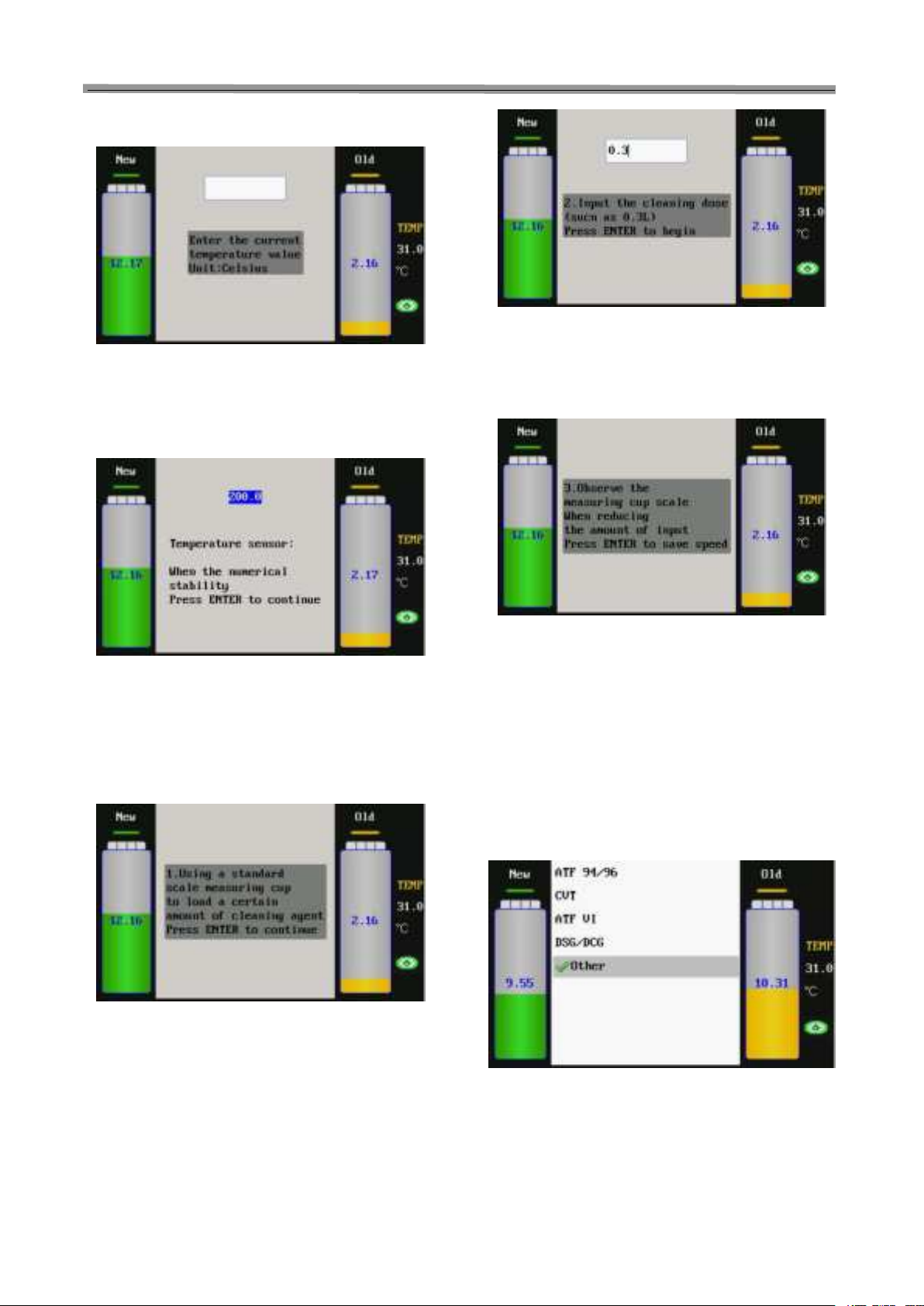
9) According to the prompts on the interface, OK the
current temperature value (Unit: ℃), and then press
OK key to save the data. The interface is as shown in
Fig.38.
Fig.38
10) When the value is stable, press OK key again to
finish the temperature sensor calibration.
11) Select “Cleaning Speed” option in the Main Menu of
[Sensor Calibration], and then press OK key to OK
the interface as shown in Fig.39.
Fig.39
12) According to the prompts on the interface, load a
certain amount of detergent to a standard measuring
cup, and then press OK key to continue. The
interface is as shown in Fig.40.
Fig.40
13) According to the prompts on the interface, OK the
amount (such as 0.3L) of detergent to be added into
the system, and then press OK key to start adding.
The interface is as shown in Fig.41.
Fig.41
14) Observe the measuring cup’s scale change status,
press OK key to save the speed value when the
detergent amount in the standard measuring cup is
decreased by 0.3L. The Cleaning Speed calibration is
finished.
9.2 Select transmission fluid
This function can choose the type of transmission fluid.
There are four types and a kind of other types, if you don't
clear transmission fluid species, can choose other. As
shown in Fig.42.
Fig.42
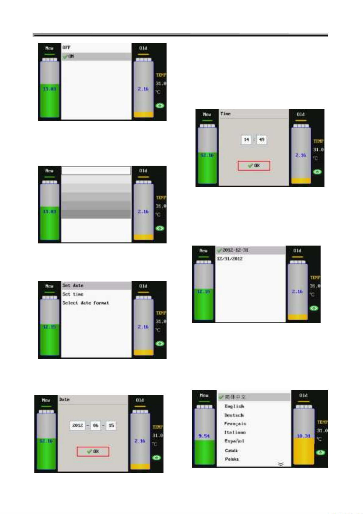
9.3 Window Light Switch Setting
Select Window Backlight Switch and press OK key to
OK the setting interface as shown in Fig.43. Press OK
key to select on or off.
CAT-601S Auto Transmission Cleaner and Fluid Exchanger User’s Manual
14
Fig.43
9.4 LCD Screen Brightness Adjustment
Select LCD Screen Brightness and press OK key to OK
the setting interface as shown in Fig.44. Press
[UP]/[DOWN] key to select the desired brightness, and
press RETURN key to confirm and return.
Fig.44
9.5 Date & Time
Select [Date & Time] option on the Main Menu of [System
Setting] and then press OK key to OK the interface as
shown in Fig.45.
Fig.45
a) Set Date
On the menu of [Date & Time], please select [Set
Date] option, and then press OK to confirm, the
interface is as shown in Fig.46.
Fig.46
According to the prompts on the interface, OK the date (4
bits for year, 2 bits for month and other 2 bits for date),
and then press OK key to confirm. The interface prompts
“OK”.
b) Set Time
On the menu of [Date & Time], please select [Set
Time] option, and then press OK to confirm, the
interface is as shown in Fig.47.
Fig.47
According to the prompts on the interface, OK the time (2
bits for hour and other 2 bits for minute), and then press
OK key to confirm. The interface prompts “OK”.
c) Select Date Format
On the menu of [Date & Time], please select [Set
Date Format] option, and then press OK to confirm,
the interface is as shown in Fig.48.
Fig.48
Select the desired date format, and then press OK key to
confirm.
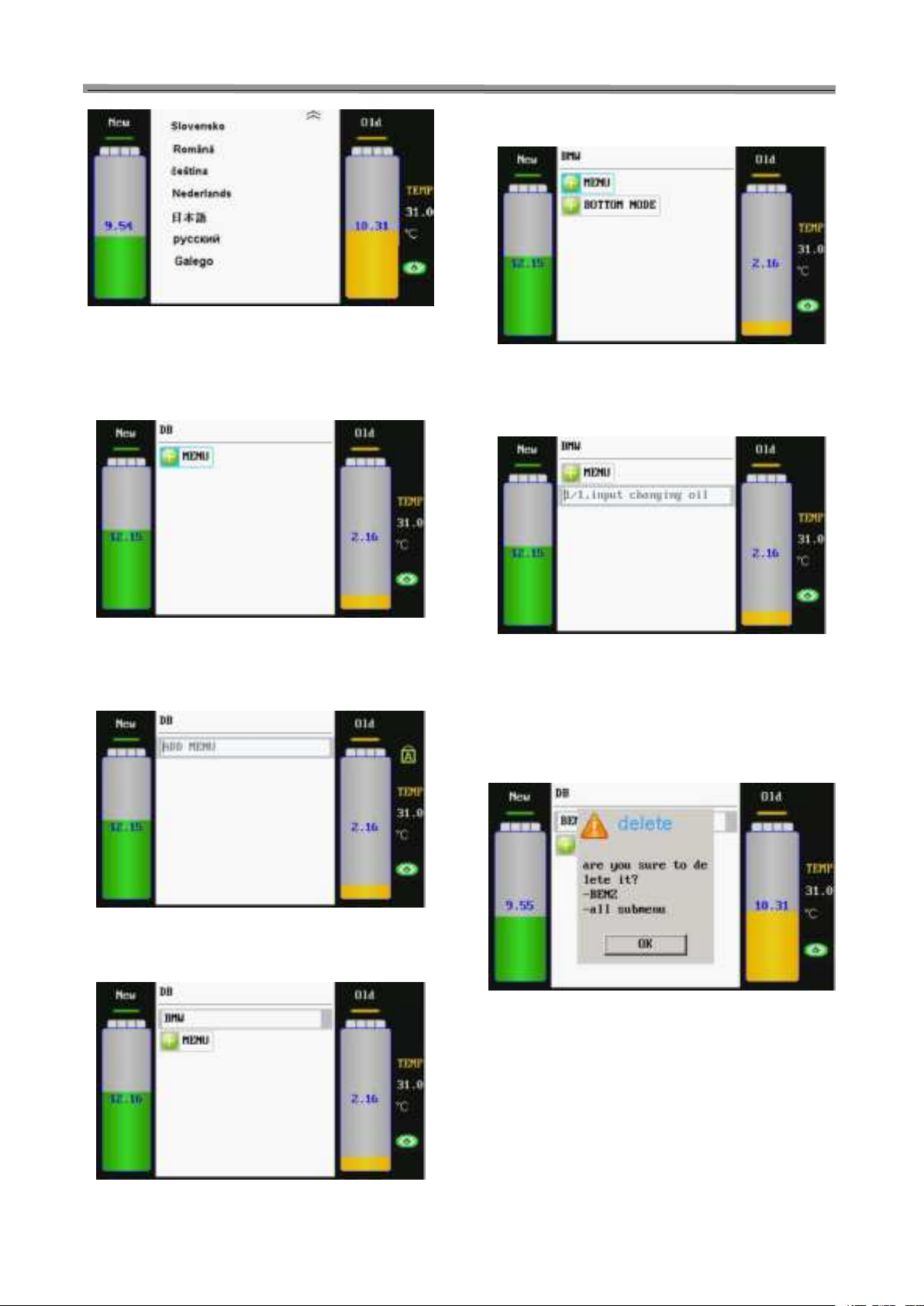
9.6 Language setting
Select the language setting and press OK key to OK
the setting interface as shown in Fig.49(a) and
Fig.49(b). Press [UP]/[DOWN] key to select the desired
language, and then press OK key to confirm and return.
Fig.49(a)
CAT-601S Auto Transmission Cleaner and Fluid Exchanger User’s Manual
15
Fig.49(b)
9.7 Vehicle Adding
Select [Vehicle Adding] setting option on the Main Menu of
[System Setting], and then press OK key to OK the
interface as shown in Fig.50.
Fig.50
Select [MENU] option, and then press OK key to OK the
interface as shown in Fig.51. Press the LIGHT key can
switch between uppercase and lowercase letters.
Fig.51
According to prompts on the interface, add the menu
(such as BMW). The interface is as shown in Fig.51.
Fig.52
Press OK key to OK the menu of BMW. The interface is as
shown in Fig.53.
Fig.53
Select [BOTTOM NODE] option can add the last layer
menu, and then press OK key to confirm. The interface is
as shown in Fig.54.
Fig.54
OK the fluid amount (such as 12.000, unit: L) to be
changed, and then press OK key to confirm performing.
Press RETURN key to return.
Select the menu option to be deleted, and then press DEL
key. The interface is as shown in Fig.55.
Fig.55
Press OK key executive delete function. Press RETURN
key to return to the previous menu directly.
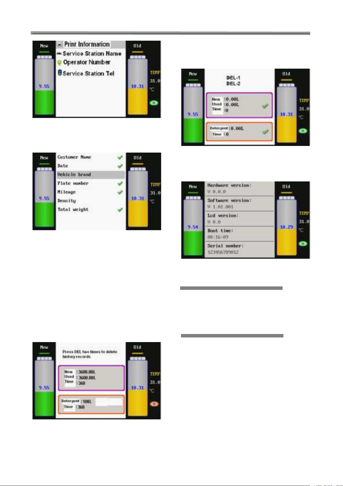
9.8 Print Setting
Select Print Setting option, the system will OK the
interface as shown in Fig.56.
CAT-601S Auto Transmission Cleaner and Fluid Exchanger User’s Manual
16
Fig.56
Print information can choose print output content. The
information contained in the options that are not selected
cannotbe printed out, as shown in Fig.57.
Fig.57
9.9 History Records
The History Records can be used to check the change
amount and time of new fluid, used fluid and detergent.
After the filters are exchanged with the new ones, it is
required to delete the original history records, otherwise
the filter status icon on the interface will not be displayed
correctly. Do not delete the original history records until
the fluid filters are exchanged, otherwise it will influence
your correct judgement to the status of the filters. When
the added fluid change amount is more than 3600L, the
system will prompt that the fluid filters are abnormal(i.e.
the filter status icon on the interface will turn orange from
green), as shown in Fig.58. It is suggested that the fluid
filters should be replaced in this case.
Fig.58
After replacing the fluid filters, press key DEL two times
on the interface of History Records to delete the original
history records, and mean while delete the prompts for
abnormal fluid filters(i.e. the filter status icon on the
interface will automatically turn green from orange), as
shown in Fig.59.
Fig.59
9.10 Device information
Select the device information option and press OK key.
The device information is displayed as shown in Fig.60.
Fig.60
Warning
Warning sound: When there is no fluid in the new tank or
the operation is completed, the unit OKs the standby
state.
Maintenance
Pay attention to each connection to check if there is
any leakage during fluid exchange. When any leak is
found, stop the CAT-601S immediately and check for
the unit. Start to exchange fluid again after
reconnection is made.
Before cleaning up the unit, the used fluid should be
drained out from the used fluid tank and the new
fluid should be drained out from new tank and stored
in container after every usage to protect the
electronic scale is on the no load state at non-work
condition.
Keep the new fluid tank clean.
Please recalibrate the electronic scale after replacing
the main-board and/or the electronic scale itself.
CAT-601S Auto Transmission Cleaner and Fluid Exchanger User’s Manual
17
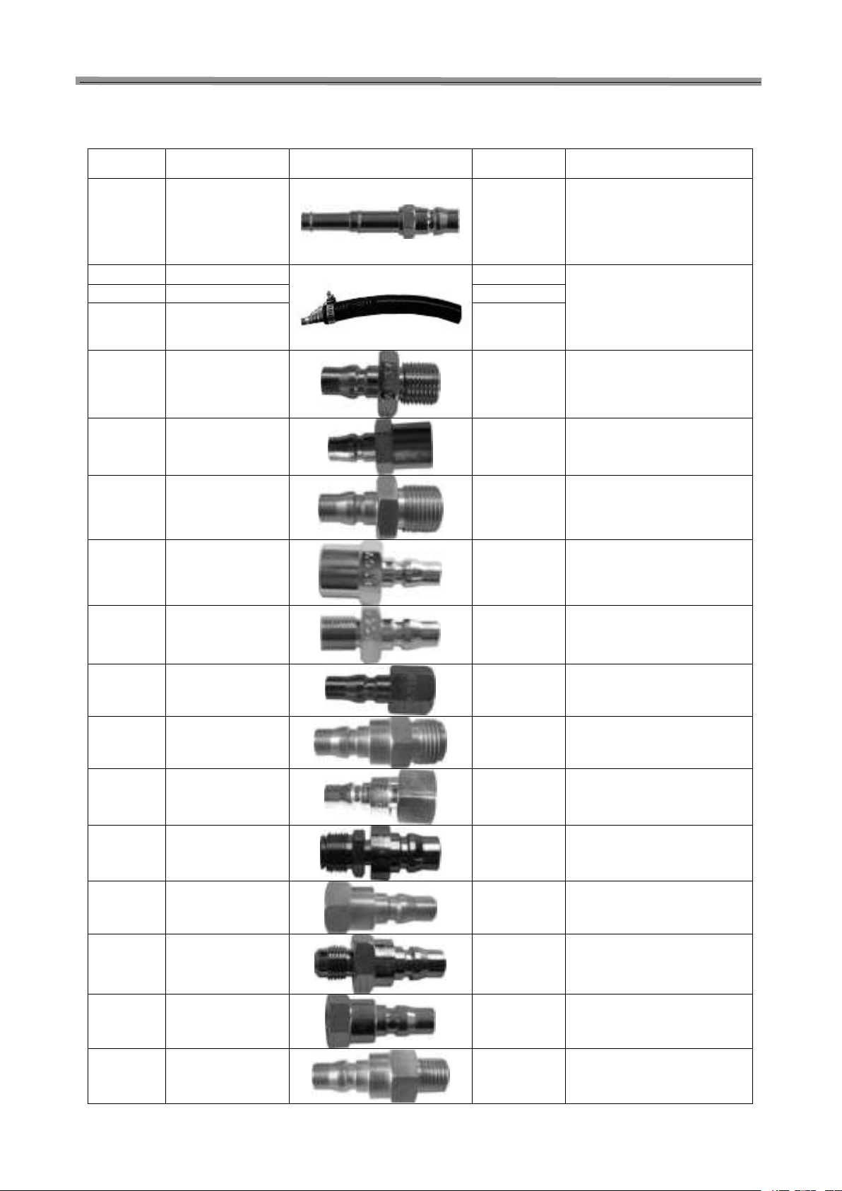
Main adapters
No. ERP Code Picture Size Applicable Car Type
A01 503240060
Φ8, Φ10,
Φ5
General type (TOYOTA,
MITSUBISHI SPACE WAGON
GLXI) LEXUS ES300,
HONDA and NISSAN car type
Φ8 Hose 606010007 Φ8 General type (TOYOTA,
MITSUBISHI SPACE WAGON
HONDA and NISSAN GLXI)
LEXUS ES300
Φ10 Hose 606010008 Φ10
Φ12 Hose 606010009
Φ12
A03A 503240064
M16×1.5
(outside)
One group CADILLAC, BMW
750 AT type 4HP-22 4HP-24
A421,MITSUBISHI V6,3000
A03B 503240028
M16×1.5
(inside)
One group CADILLAC, BMW
750 AT type 4HP-22 4HP-24
A42
A05A 503240029
M18×1.5
(outside)
EUROPEAN
Eg: New VECTRA, PASSAT
A05B 503240030
M18×1.5
(inside)
EUROPEAN
New VECTRA, PASSAT
A06A 503240031
G1/4 (outside) CHRYSLER
GRAND VOYAGER,
CHRYSLER 300
A06B 503240032
G1/4 CHRYSLER 13.157mm
GRAND VOYAGER,
CHRYSLER 300
A07A 503240033
M18×1.5
(outside)
EUROPEAN
New VECTRA
A07B 503240034
M18×1.5
(inside)
EUROPEAN
New VECTRA
A08A 503240035
UNF1/2-20
(outside)
GENERAL MOTORS
LINCOLN, CADILLAC
A08B 503240036
UNF1/2-20
(inside)
GENERAL MOTORS
LINCOLN, CADILLAC
A10A 503240037
UNF1/2-20
(outside)
FORD, eg: VOLVO, FORD
CHRYSLER: DAIMLER-BENZ
A10B 503240038
UNF1/2-20
(inside)
FORD, eg: VOLVO, FORD
CHRYSLER: DAIMLER-BENZ
A11A 503240039
Z1/4 *18
13.616
FORD
LINCOLN, VOLVO
Table of contents
Other SmartSafe Ultrasonic Jewelry Cleaner manuals


