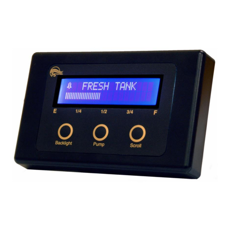
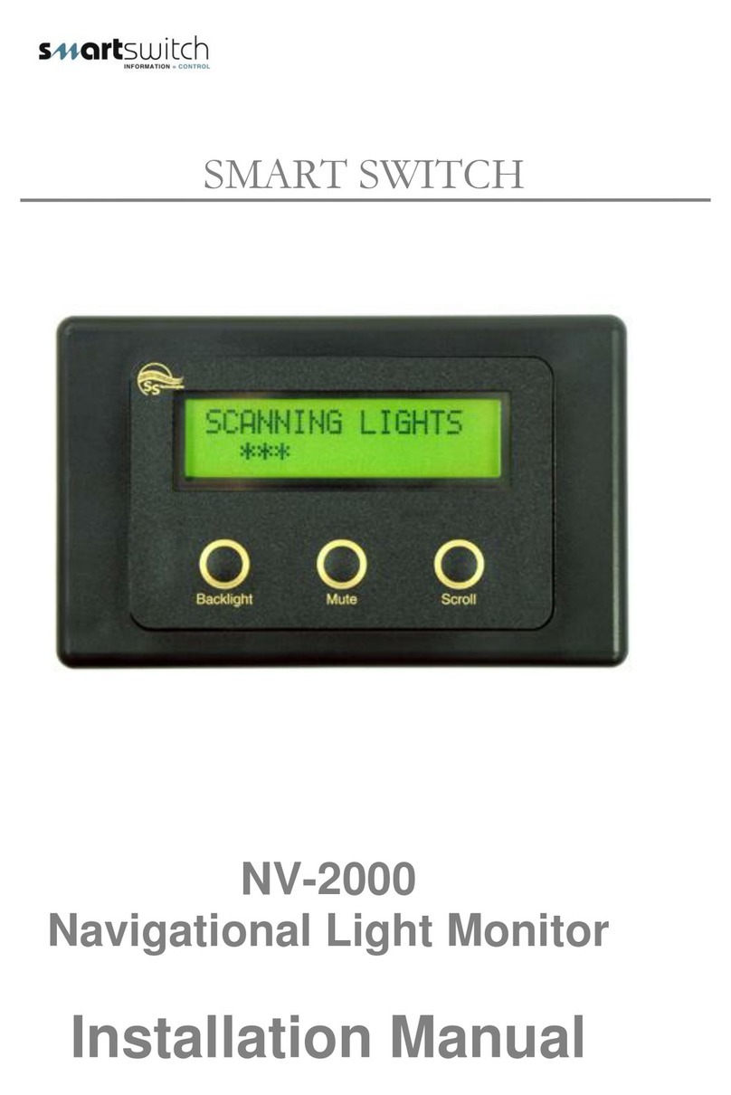
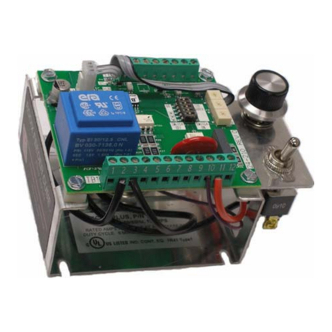
Smartswitch TC-8000 User manual

SMARTSWITCH
TC-8000
Tank Monitor/Controller
Installation Manual

Introduction 1
System Overview 2
Wiring Block Diagram 3
System Layout 4
Wiring Diagram (HT-100 & HB-200) 5
Wiring Diagram (HT-100/P & HB-200/P) 6
Product Photos 7
Installation Steps 8
Mounting Instructions 9
Sensor Installation 10
Sensor Programming Instructions 11
Sensor Programming Instructions (cont.) 12
Setting Rotary Switch (network address) 13
Seacock Interlock Switch Installation 14
Pump Current Sensing 15
Programming Instructions 16
Programming Instructions (cont.) 17
Programming Instructions (cont.) 18
Programming Instructions (cont.) 19
Programming Instructions (cont.) 20
Operating Instructions 21
Operating Instructions (cont.) 22
Operating Instructions (cont.) 23
Electrical Specifications 26
Table of Contents

1
Thank you for purchasing the TC-8000 Holding Tank Controller.
Smartswitch is very proud to be able to provide this product to you.
The Smartswitch Research and Development Team has spent considerable time and
effort in developing, designing and producing this system specifically for the marine
environment. We see this as a first in the marine environment and consider
Smartswitch to be leading the world in the design and development of distributable
intelligence controller systems.
The Holding Tank Controller has been developed with intelligent intervention for
monitoring fluid levels and controlling pumps on up to 8 tanks.
The Smartswitch Holding Tank Controller is a versatile, compact, modern, stylish, user-
friendly intelligent network system.
The TC-8000 allows builders and retrofitters to offer a system with maximum
functionality thereby providing boat owners with easy and accurate management.
Installation
Smartswitch recommends a Qualified Marine or Auto-Electrician installs this product.
Introduction

2
System Overview
TC-8000 Master Display Unit (MDU)
Provides the following functions:
•full control from one central location on your boat
•visual indication of tank level (bar graph or lts / gals & percentage)
•visual indication of seacock position & pump status
•ability to turn holding tank macerator pump on & off manually or automatically
•ability to turn holding tank macerator pump on manually & off automatically
•all tanks are name programmable e.g. (Aft-Grey) (Port Fuel) (Aft-Fuel)
•audible alarm
•backlight
HT-100 or HB-200 or HT-100/P or HB-200/P Input/Output
Unit:
Is a controller which provides an input for the fluid level sensor. Each tank on the network
requires an IOU. The HT-100 or HB-200 allow for monitoring only while the
HT-100/P or HB-200/P provide monitoring and management of pumps connected to them.
The HT-100 or HT-100/P is to be used if using the pressure sensor.
The HB-200 is used with the ultra-sonic sensor for monitoring only.
The HB-200/P is duel purpose and used for the ultra-sonic sensor or the pressure sensor for
both monitoring and pump control.
Features include:
•teach-in level sensor with 5 point interpolation for irregular shaped tanks
•controls the pump and provides the input for the level sensor
•reversed output for tanks programmed as either fuel, enabling for fuel transfer pumps
to turn on when the tank is empty and off when full
•tank high level output which can be connected to the Aus/Sea toilet controller and will
disable the toilet when the holding tank is full
•an internal pump on/off override switch for tank servicing and cleaning
•supplied in two different models:
HT-100 or HB-200 features level sensor and tank high output
HT-100/P or HB-200/P features level sensor, tank high output, pump & electric
seacock control
RD-800 Remote Display Unit (RDU)
The RD-800 Repeater Display is an optional extra.
Any number of these may be connected throughout the vessel for convenient tank
monitoring. Note: The RDU is for monitoring only and will not allow control.

3
WARNING: As the HT-100/P & HB-200/P supply power for the pump, the supply
cables & fuse need be rated as per the pump manufacturer’s specifications.
Black
Battery
negative
Red
Battery
positive
Display Unit
TC-8000
Display Unit
RD-800
Batt +
Batt -
White=Net -
Blue=Net +
High Relay
Sensor
Pump
White=Net -
Blue=Net +
White = Net –
Blue = Net +
Wiring Block Diagram
Sensor
- +
Battery
To next device
HT-100/P or
HB-200/P (IOU)
HT-100 or
HB-200 (IOU)

4
Tank full
Disable output
Pump
Tank full
Disable output
Tank full
Disable output
Model RD-800
Eight Channel Holding Tank Controller System Layout for Model TC-8000
Any Device can sit Anywhere on this Two Core Bus cable.
Any combination of HT-100/P, HB-200/P and or HT-100, HB-200 (up to eight) can be connected, plus any number of repeater display units - Model RD-800.
NOTE: The HT-100/P & HB-200/P have the pump and valve option, while the HT-100 & HB-200 do not.
HT-100/P or HB-200/P
Tank
Sensor
Input/Output
Controller
Pump
Tank
Sensor
Input/Output
Controller
Pump
HT-100/P or HB-200/P
Tank full
Disable output
Tank
Sensor
Input/Output
Controller
HT-100/P or HB-200/P
Tank
Sensor
Input Controller
HT-100 or HB-200
Tank full
Disable output
Tank
Sensor
Input Controller
HT-100 or HB-200
Tank full
Disable output
Tank
Sensor
Input/Output
Controller
Pump
HT-100/P or HB-200/P
Fuel transfer
pump
Input/Output
Controller
Model TC- 8000
Model RD-800
Water Pump
Tank
Sensor
Input/Output
Controller
HT-100/P or HB-200/P
HT-100/P or HB-200/P
Tank Sensor in
the Day Tank.
See page 18
2 core Network cable

5
Wiring For Pressure Sender SEN-B300
Gnd = Black on Pressure Sensor
Sensor In = Green on Pressure Sensor
+ 5 vdc = Red on Pressure Sensor
Wiring For Ultra-Sonic Sender
Gnd = Black on Ultra-Sonic Sensor
Sensor In = Green on Ultra-Sonic Sensor
Battery + = Red on Ultra-Sonic Sensor
Wiring Diagram for Model HT-100
LED
Program Button
Rotary Switch
Network Cable
Net -
Net +
Com
N/C
N/O
Relay
Tank
sensor
Wiring Diagram for Model HB-200
LED
Program Button
Rotary Switch
Sensor In
Gnd
+ 5 vdc
Network
Net -
Net +
Com
N/C
N/O
Relay
Battery -
Battery +

6
If no Seacock Interlock Switch is used then place a jumper between Link and V/In1 (see page 14)
Pump positive
Pump negative
Battry negative
Battery positive
Tank
sensor
LED
Program Button
Rotary Switch
GND
V/ln2
V/ln1
V/Out
Link
Com
N/C
N/O
Relay Two
Wiring Diagram for Model HT-100/P
Network Cable
Net -
Net +
Com
N/C
N/O
Relay One
Pump positive
Pump negative
Battery negative
Battery positive
Tank
sensor
LED
Program Button
Rotary Switch
V / INPUT
+ 12 VDC
GND
Sensor Input
+ 5 VDC
Com
N/C
N/O
Relay Two
Pressure sender
Com
N/C
N/O
Relay One
Network Cable
Net -
Net +
Wiring Diagram for Model HB-200/P
Pressure
Sensor Wires
Black
Green
Red

7
HB-200 Input/Output Unit
Rotary Switch
Program Button
LED
HT-
SEN-100/250 Plug Connection
Rotary Switch
Program Button
Notch for Sensor wire in case
LED
HT-100/P or HB-200/P Input/Output Unit

8
Step 1:
Install and connect the Master Display Unit.
Step 2:
Install, connect and calibrate the tank sensors.
Step 3:
Install and connect the I/O units (HT-100, HB-200 or HT-100/P, HB-200/P).
Step 4:
Set-up Rotary Switches.
Step 5:
Seacock Interlock Switch or Jumper.
Step 6:
Set-up Pump Sensing.
Step 7:
Program the Master Display Unit.
Step 8:
Test system.
Installation Steps

9
Position the mounting template tool provided and mark all three pilot holes. Drill a 3mm hole on the two outside
holes and fit the mounting screws provided. Place the template tool back over the screws and tighten the screws
until the template tool can just slip on and off the screws (ensure the tool in not too loose).
Drill the bottom hole to 12 mm (cable hole).
Place the Display Unit keyholes over the two screws and gently pull down. If the screws have been tightened to the
correct depth the Display will clip down and self tighten.
If the Smartswitch pressure sensor is being fitted see pages 10, 11 and 12.
PLEASE NOTE: If a charcoal filter is fitted to the Black tank see Special Pump (page 19)
If the Ultra-Sonic sensor is being fitted see page 12.
Mounting the TC-8000 Master Display Unit
Sensor Installation
Pilot Holes
Pilot Hole
Sensor Installation

10
PLEASE NOTE: If a charcoal filter is fitted to the Black tank see Special Pump (page 19)
PLEASE NOTE: For sensor Model SEN-100 The Maximum Tank Height is 1 Meter
PLEASE NOTE: For sensor Model SEN-250 The Maximum Tank Height is 2.5 Meter
The maximum surge and safe pressure is 28psi.
For more information see “Calibration Tips & Tricks” on our web site
www.smartswitch.co.nz
Mounting Adaptors Available:
A range of mounting adaptors are available which include flat sidewall, top mount, 1.5” pipe, 2” pipe, 3” pipe and drain
valve. Ask your dealer for details.
Interface Adaptors:
Should a 4 to 20 milliamp loop sensor supplied by another manufacturer be used, then the adaptor (part number SM-
420) will need to be installed.
Should a 0 to 180 or 33 to 230 ohm sensor supplied by another manufacturer be used, then the adaptor (part number
SM-180) will need to be installed.
Sensor Installation:
The sensor should be mounted as low in the sidewall as possible using a ¾” spin-in or the flat sensor adaptor. If the
sensor adaptor is used it will require drilling a 5/8” hole in the sidewall. Apply silicon glue liberally to the bottom of the
adaptor. Using #10 x ½” stainless steel self-tapping screws attach the adaptor to the sidewall. Once the adaptor is
attached make sure that the hole in the adaptor is clear of any excess glue. Allow drying as per the instructions for the
glue. Wrap the threads of the sensor using Teflon plumbers tape and install the sensor. Tighten by hand. It is not
recommended to install the sensor in the bottom of the tank. Although the sensor will operate correctly it will provide an
area for debris to collect which would be difficult to flush out.
! WARNING !
Tank
Top mount adaptor
(Tube not supplied)
Tank
Sidewall adaptor
Tank
The top-mounting adaptor requires 3/4" ABS or
PVC pipe cut to the proper length so that the
pipe is about 1/2" from the bottom of the tank.
This pipe glues into the adaptor and the sensor
screws into the top of the adaptor. It is held on
with 2 self-tapping screws. Care must be taken
that the sensor threads are sealed with teflon
tape and screwed in tight to ensure no air
leaks, as the tube must remain pressurized.
The sensor will be damaged if subject to over
pressure during installation, caused by
compressing the small air gap between the
sensor and the ball valve.
DO NOT PRESSURE TEST TANK WITH SENSOR FITTED
Pipe adaptor
Valve

11
Two different methods of tank programming are available if using the pressure sensor:
2 Point Calibration: sets tank low and tank high points which can only be used if the tank is a regular size and
shape.
5 Point Calibration: sets tank low, tank quarter, tank half, tank three quarters and tank full points, offering more
accuracy if the tank is an irregular size and shape.
2 Point Calibration:
Turn Rotary Switch on the I/O Box to position 0
When calibration mode is entered (holding down the program button for 3 seconds) the LED will flash very fast,
while the I/O Box is calculating the Empty point. Once this has finished you will see Three slow flashes and the
LED will stay on indicating it has programmed the Empty point. It is now ready to set the Full point.
When the button is pressed again, to set the Full point, the LED will flash very fast, while the I/O Box is calculating
the Full point. Once this has finished you will see Three slow flashes indicating it has programmed the Full point.
The LED will then turn off.
NOTE: While the fast flashing continues it is indicating the tank contents have not settled enough for the unit to
take a good reading (wait for the contents to settle).
NOTE: If you see 12 slow flashes this indicates the unit could not see any difference between the Empty point
setting and the Full point setting. The Empty and Full points need to be different.
Turn Rotary Switch to correct position (see Setting Rotary Switch page 13)
Note: The Bottom Only, Top Only and Setting The Calibration From One IOU To Another, only applies to HT-100 or HT-
100P units with manufacture dates after March 2007.
After calibrating the bottom and top settings of a tank you may wish to go back and change either of these
settings individually:
The Bottom Only setting can be changed by turning the Rotary Switch to position A
Fill the tank to the required TANK LOW LEVEL, minimum suggested is liquid just covering the sensor. Wait approx. 30
seconds for the fluid to settle. Press and hold down the Program Button (on the IOU) until the LED starts to fast flash
(approx. 3 seconds) release the button, the LED will fast flash until the contents are stable, then the LED will give 3 slow
flashes and turn off. The tank low point has now been saved and the unit will automatically leave program mode. The
device is now ready for use.
Turn Rotary Switch to correct position (see Setting Rotary Switch page 13)
The Top Only setting can be changed by turning the Rotary Switch to position B
Fill the tank to the required TANK FULL LEVEL and wait approx. 30 seconds for the fluid to settle. Press and hold down
the Program Button (on the IOU) until the LED starts to fast flash (approx. 3 seconds) release the button, the LED will
fast flash until the contents are stable, then the LED will give 3 slow flashes and turn off. The tank high point has now
been saved and the unit will automatically leave program mode.
The device is now ready for use.
Turn Rotary Switch to correct position (see Setting Rotary Switch page 13)
Tank
High Point
Low Point
Sensor Programming Instructions

12
5 Point Calibration:
Turn Rotary Switch (IOU) to position F
When calibration mode is entered (holding down the program button for 3 seconds) the LED will flash very fast,
while the I/O Box is calculating the Empty point. Once this has finished you will see Six slow flashes and the LED
will stay on indicating it has programmed the Empty point. It is now ready to set the 1/4 point.
When the button is pressed again, to set the 1/4 point, the LED will flash very fast, while the I/O Box is calculating
the 1/4 point. Once this has finished you will see Two slow flashes indicating it has programmed the 1/4 point. The
LED will stay on indicating it has programmed the 1/4 point. It is now ready to set the 1/2 point.
When the button is pressed again, to set the 1/2 point, the LED will flash very fast, while the I/O Box is calculating
the 1/2 point. Once this has finished you will see Three slow flashes indicating it has programmed the 1/2 point.
The LED will stay on indicating it has programmed the 1/2 point. It is now ready to set the 3/4 point.
When the button is pressed again, to set the 3/4 point, the LED will flash very fast, while the I/O Box is calculating
the 3/4 point. Once this has finished you will see Four slow flashes indicating it has programmed the 3/4 point. The
LED will stay on indicating it has programmed the 3/4 point. It is now ready to set the Full point.
When the button is pressed again, to set the Full point, the LED will flash very fast, while the I/O Box is calculating
the Full point. Once this has finished you will see Five flashes indicating it has programmed the Full point. The LED
will then turn off.
NOTE: While the fast flashing continues it is indicating the tank contents have not settled enough for the unit to
take a good reading (wait for the contents to settle).
Turn Rotary Switch to correct position (see Setting Rotary Switch page 13)
Setting The Calibration From One Input/Output Unit To Another:
Once the IO/Box has been calibrated you can transmit the calibration settings from that unit to as many more as
required (tanks would need to be the same shape, size and content).
The I/O Box can transmit to, or receive from, any I/O Box and vice versa.
Note: This must be done independently from the complete system setup (only the 2 IOU’s connected).
Step 1: Connect the power and network cable to both units.
Step 2: Turn the Rotary Switch to position C for the master transmitter (the unit that is calibrated).
Step 3: Turn the Rotary Switch to position D for the slave receiver (the unit that needs calibrating).
You will see both LED’S flashing, please wait (approx 20 seconds) for the LED’S to stop flashing, the slave receiver
now has the same calibration setting as the master transmitter.
For more information see “Calibration Tips & Tricks” on our web site www.smartswitch.co.nz
Ultra-Sonic Sensor :
If using the Ultra-Sonic sensor turn the Rotary Switch to position 1
Press and hold down the Program Button for 3 seconds, the LED will flash 4 times and turn off.
Turn Rotary Switch to correct position (See Setting Rotary Switch page 13
Tank
High Point
Low Point
3/4 Point
Half Point
1/4 Point

13
Setting Rotary Switch (Network Address)
Each Input/Output Unit (HT-100, HB-200 or HT-100/P, HB-200/P) on the network must
have the Rotary Switch set to a unique number (from 2 to 9). NO two devices may share the same
Rotary Switch number.
The Rotary Switch is situated inside the Box of the HT-100/P and HB/200P Input/Output Unit and on the outside of the
case on the HT-100 and HB-200 (see diagrams below and page 7 for position).
For ease of reference fill in Table 1 below prior to programming as this will enable quick reference when programming the
Display Unit. See example below.
Swit Switch #
Tank Position
Tank Type
Tank Vol
2
AFTPORT
GREY
400L
Table 1
Example
HT-100/P & HB-200/P (Inside Case)
HT-100 & HB-200 (Side of Case)
Tank
sensor
LED
Program Button
Rotary Switch
LED
Program Button
Rotary Switch

14
Seacock Interlock Switch Installation
Important: The HT-100/P and the HB-200/P provide for an interlock with a seacock valve to prevent the pump
from starting in the event the seacock valve is closed. In the event there is no interlock contact on the
seacock, the following procedure MUST be followed to allow the pump to operate in either manual or
automatic mode.
If an Interlock Switch is fitted then wire as follows. When the Seacock Valve is closed and the pump is activated, the
pump will not turn on and the system will alarm you (see Alarms page 22).
HB-200/P
HT-100/P
Note: For the HT-100/P ONLY, in the event there is no interlock contact on the seacock, the following
procedure MUST be followed to allow the pump to operate in either manual or automatic mode: Place a link
wire between the Link & V/In 1 terminals (see page 6 for diagram)
Tank
sensor
LED
Program Button
Rotary Switch
Switch Input
+ vdc
Seacock Switch
Tank
sensor
LED
Program Switch
Rotary Switch
GND
V/In 2
V/In 1
V/Out
Link
Seacock switch
If NO Interlock
switch is fitted
then no action
is required
If NO If If NO Interlock Switch is fitted:
Place a Place a link wire between the Link &
V/In 1 terminals (see page 6 for
diagram)

15
The HT-100/P & HB-200/P are equipped with special current sensing circuitry to detect if after a pump is turned
on, it is in fact running.
If a pump is turned on, either Manually or Automatically, and the pump fails to start due to short or open circuit, the
pump icon for that tank will flash and the alarm will sound indicating a fault. Pressing the Mute key will mute the alarm.
If the attached load/pump is below the current sensing range, or the output is connected to a relay, then this feature will
need to be disabled.
This option can be enabled or disabled by the position of the Current Sensing Control Jumper.
To Enable this feature Remove the Jumpers.
To Disable this feature Insert the Jumpers.
Pump Current Sensing
Pump positive
Pump negative
Battery negative
Battery positive
Tank
sensor
LED
Program Button
Current Sensing
Control Jumper
.
.

16
Programming Instructions
Step 1: Placing the unit in Program Mode
Press and hold down the Mute & Select Up keys together for 3 seconds. This will bring you to the Set-Up Menu and
place the unit in program mode.
Scroll to PROGRAM TANK and press the Mute key.
Note: After a tank has been programmed any of the settings may be changed by scrolling to the option
requiring changing and pressing the Mute key.
Step 2: Programming a Tank
Once in program mode each tank can be individually programmed and the screen will display: “Select Switch # ”. Use
the Select Up or Down key to change the Switch number which corresponds to the I/O unit you wish to program (refer to
Table 1 on page 13) for Switch number.
Once the Switch number has been selected press the Mute key.
Step 3: Selecting Tank Name
The display will now show:
NOTE: There is a list of pre-programmed names for you to choose from, if you want to change a name see step 3a
below. Once a name has been used DO NOT use the same name again when programming another tank choose
another name from the list to either use or change.
Use the Select Up or Down key to scroll through the pre-programmed tank names. Press the Mute key once the
required name has been found. Otherwise if you would like to change the name, press the Pump key and see next
step 3a.
Step 3a: Changing Tank Name Text
The tank name text may be changed. After selecting the Tank (name), as above, use the Dim Up or Down key to
move the cursor to each individual letter and the Select Up or Down key to scroll through the alphabet. Press the
Mute key to enter, once you have finished.
SET-UP MENU
PROGRAM TANK
SUB MENU
DAY TANK MENU
ERASE TANK
EXIT MENU
Push Mute To ENTER
GREY TANK
Select TankText #
Push PUMP To Change
Push MUTE To Enter

17
Step 4: Selecting Tank Type
The display will now show:
Use the Select Up or Down key to scroll through the tank various types (note this is not the tank name, it is the tank
type). Press the Mute key once the appropriate tank type has been found.
Step 5: Setting the Alarm Point
The display will now show:
Use the Select Up or Down key to scroll through the tank levels 0 to 16 bars. (0 = Empty 16 = Full). Once you have
selected the required level, of the alarm trigger point, press the Mute key.
Step 6: Audible Alarm
The screen will now display: “DO YOU WANT AN AUDIBLE ALARM”.
Press the Select Up key to select “Yes” or the Select Down key to select “No”.
If Yes is selected the audible alarm will sound based on the Alarm Point as set above.
If No is selected there will be no audible alarm associated with that tank, only a visual bell.
Step 7: Tank Volume (see Note 1 page 24)
The screen will now display: “DO YOU WANT TO SET TANK VOLUME”.
This allows for displaying the tank volume in either Liters or Gallons. If this feature is required press the Select Up key to
select “Yes”. Next select “Ltrs” for Liters or “Gal” for Gallons.
The screen will now display: “Set Vol 00000”. Use the Select Up and Down key to change the value of each digit and
the Mute key to enter and move to the next digit. . When the last digit is reached and the Mute key is pressed, the system
will save all associated data programmed for that particular tank and return to the Set-Up Menu.
Otherwise press the Select Down key to select “No”. The system will save all associated data programmed for that
particular tank and return to the Set-Up Menu.
You have now completed the programming of a particular tank. This must be repeated for all additional tanks.
Grey=1 Black=2
Fuel=4 Water=3
Select TankType #
Use Select Keys
Push MUTE To Enter
Set Alarm On Point
Use Select Keys
Push MUTE To Enter
E ############# F

18
Erasing Tanks:
A tanks data may be completely erased. From the Set-Up Menu scroll to ERASE TANK and press the Mute key.
The display will now show:
Use the Select Up or Down key to scroll through the Switch numbers to the tank that requires erasing. Once the tank is
displayed press the Mute key. Or to exit this screen and return to the Set-Up Menu press the Pump key.
The display will now show:
Use the Select Up key for YES or the Select Down key for NO. If Yes is selected the Tank Position and Type will be
erased for that Switch position and the unit will return back to the Set-Up Menu. If No is selected the unit will return
back to the Set-Up Menu.
Day Tank Menu:
This menu allows you to set where the fuel is coming from and where it is going to. This allows for automatic cut off if the
supply tank is empty.
The display will now show:
Use the Select Up or Down key to scroll through to the tank fuel is TRANSFERING TO. Once the tank is displayed press
the Mute key.
GREY TANK
Select Switch #
Push MUTE To Enter
Push PUMP To EXIT
GREY TANK
Are You Sure
Yes No
PORT DAY FUEL
SELECT THE TANK
FUEL IS GOING TO
Use Select Keys
Push MUTE To Enter
NOTE: The transfer pump needs to be connected to the Tank Controller (HT-100/P or HB-200/P)
that is monitoring the Day Tank .
This is the DAY TANK
Table of contents
Other Smartswitch Controllers manuals
Popular Controllers manuals by other brands
Siemens
Siemens Simatic S7-1500 manual
Honeywell
Honeywell 10260S series Replacement instructions
Avonic
Avonic CM-CON100 user manual

Ametek
Ametek 88740.01210 Translation of the original function and connection guide
Chamberlain
Chamberlain Garos CS 300 operating instructions
Befaco
Befaco VCMC Assembly guide
