manuals.online logo
Brands
  1. Home
  2. •
  3. Brands
  4. •
  5. SMC Networks
  6. •
  7. Chiller
  8. •
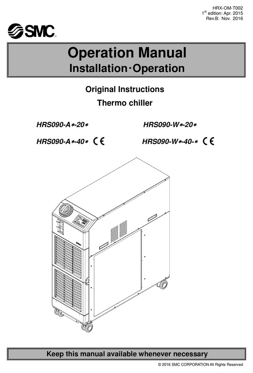
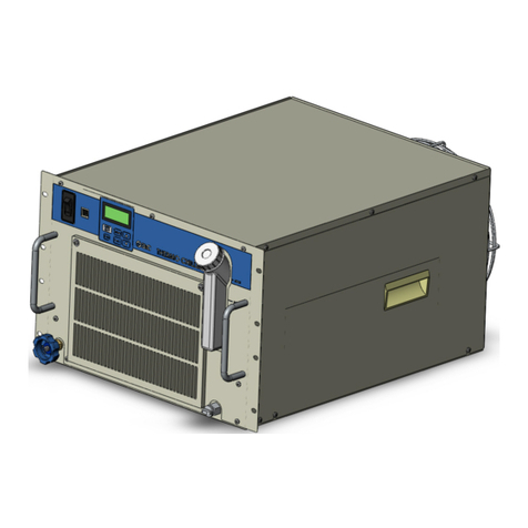
  9. SMC Networks HRSH Series Series User manual

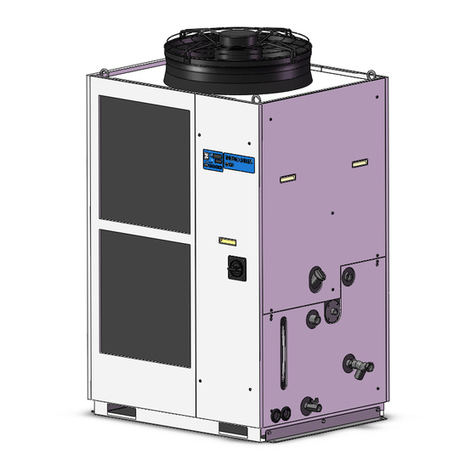
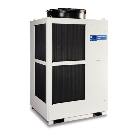
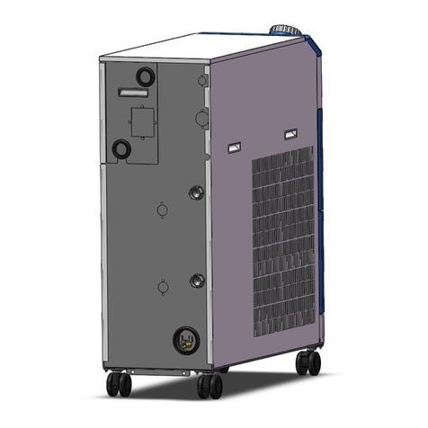
SMC Networks HRSH Series Series User manual

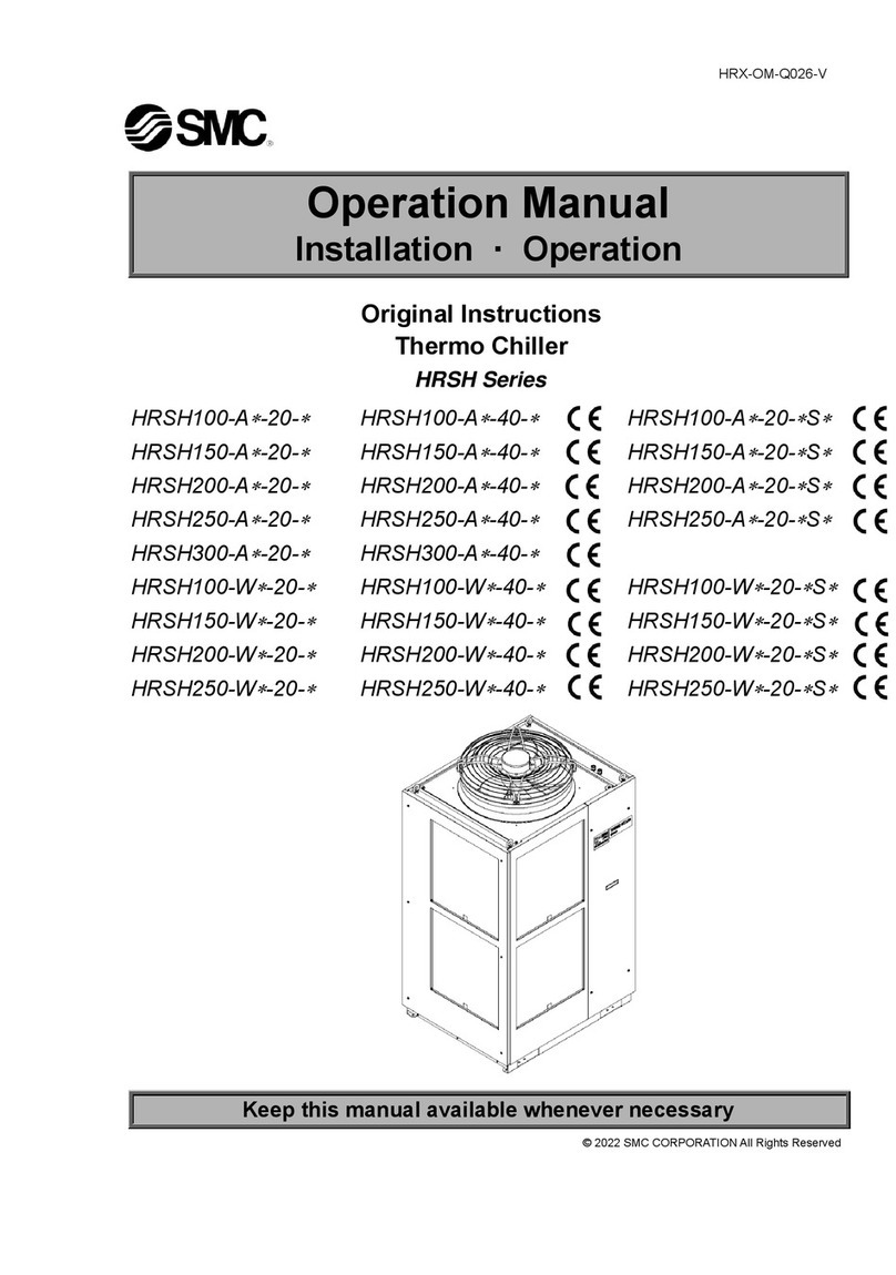
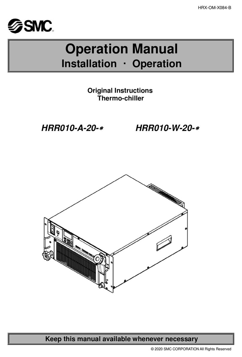
HRX-OM-Q026-T
Operation Manual
Installation ・ Operation
Original Instructions
Thermo Chiller
HRSH Series
HRSH100-A

-20-

HRSH150-A

-20-

HRSH200-A

-20-

HRSH250-A

-20-

HRSH300-A

-20-

HRSH100-W

-20-

HRSH150-W

-20-

HRSH200-W

-20-

HRSH250-W

-20-

HRSH100-A

-40-

HRSH150-A

-40-

HRSH200-A

-40-

HRSH250-A

-40-

HRSH300-A

-40-

HRSH100-W

-40-

HRSH150-W

-40-

HRSH200-W

-40-

HRSH250-W

-40-

HRSH100-A

-20-

S

HRSH150-A

-20-

S

HRSH200-A

-20-

S

HRSH250-A

-20-

S

HRSH100-W

-20-

S

HRSH150-W

-20-

S

HRSH200-W

-20-

S

HRSH250-W

-20-

S

Keep this manual available whenever necessary
© 2021 SMC CORPORATION All Rights Reserved
To the users
Thank you for purchasing SMC’s Thermo chiller (hereinafter referred to as the “product”).
For safety and long life of the product, be sure to read this operation manual (hereinafter referred to
as the “manual”) and clearly understand the contents.
Be sure to read and follow all instructions noted with “Warning” or “Caution” in this manual.
This manual is intended to explain the installation and operation of the product. Only people who
understand the basic operation of the product through this manual or who perform installation and
operation of or have basic knowledge about industrial machines are allowed to work on the product.
This manual and other documents attached to the product do not constitute a contract, and will not
affect any existing agreements or commitments.
It is strictly prohibited to copy this manual entirely or partially for the use by a third party without prior
permission from SMC.
Note: This manual is subject to possible change without prior notice.
HRX-OM-Q026
Contents
HRSH Series
Contents
Chapter 1 Safety Instructions .........................................................1-1
1.1 Before Using the Product ....................................................................................... 1-1
1.2 Reading the Manual ................................................................................................ 1-1
1.3 Hazards .................................................................................................................... 1-2
Level of hazards .................................................................................................................. 1-2
Definition of “Serious injury” and “Minor injury”................................................................... 1-2
1.4 Product Label .......................................................................................................... 1-3
1.5 Safety Measures ...................................................................................................... 1-4
Safety instructions for use ................................................................................................. 1-4
Personal protective equipment............................................................................................ 1-4
1.6 Emergency Measures.............................................................................................. 1-5
1.7 Waste Disposal........................................................................................................ 1-5
Disposal of refrigerant and compressor oil.......................................................................... 1-5
Disposal of product.............................................................................................................. 1-5
1.8 Material Safety Data Sheet (MSDS) ........................................................................ 1-6
Chapter 2 Name and Function of Parts............................................2-1
2.1 Model Number of Product....................................................................................... 2-1
2.2 Name and Function of Parts................................................................................... 2-2
HRSH-A-(Air cooled type)......................................................................................... 2-2
HRSH-W-(Water cooled type)................................................................................... 2-3
2.3 Function of Parts..................................................................................................... 2-4
2.4 Operation Display Panel ......................................................................................... 2-5
Chapter 3 Transport and Setting Up.................................................3-1
3.1 Transport.................................................................................................................. 3-1
Transportation using forklift and hanging ............................................................................ 3-2
Transportation using casters ............................................................................................... 3-3
3.2 Installation ............................................................................................................... 3-4
Environment ........................................................................................................................ 3-4
Operation at low ambient temperature or low circulating fluid temperature........................ 3-6
Operation at high ambient temperature .............................................................................. 3-7
Location............................................................................................................................... 3-7
Installation and maintenance space.................................................................................... 3-9
3.3 Installation ............................................................................................................. 3-10
Installation ......................................................................................................................... 3-10
Electrical wiring ................................................................................................................. 3-12
Preparation and wiring of power supply cable .................................................................. 3-14
Contact input/output communicatin wiring ........................................................................ 3-19
HRX-OM-Q026
Contents
HRSH Series
Wiring of run/stop signal input and remote signal input.....................................................3-19
Wiring of external switch signal input ................................................................................3-22
Wiring of contact output signal ..........................................................................................3-25
RS-485 communication wiring...........................................................................................3-26
RS-232C communication wiring ........................................................................................3-27
3.4 Piping......................................................................................................................3-28
3.5 Circulating Fluid Supply........................................................................................3-31
Automatic water fill function...............................................................................................3-31
Fluid supply without using the automatic water fill function...............................................3-33
Option K “Water fill port” ....................................................................................................3-35
Chapter 4 Starting the Product......................................................... 4-1
4.1 Before Starting.........................................................................................................4-1
4.2 Preparation for Start ................................................................................................4-2
Power supply .......................................................................................................................4-2
Option B “Earth leakage breaker”........................................................................................4-2
HRSH--20-B1 HRSH--20-S and HRSH--40-..........................................4-3
Setting of circulating fluid temperature ................................................................................4-3
Setting of pump operation mode .........................................................................................4-3
4.3 Preparation of Circulating Fluid Supply to User’s Equipment..............................4-4
4.4 Operation Start and Stop.........................................................................................4-7
Starting the product .............................................................................................................4-7
Stopping the product............................................................................................................4-8
4.5 Check Items during Startup ....................................................................................4-9
4.6 Adjustment of Circulating Fluid Flow Rate ............................................................4-9
Chapter 5 Display and Setting of Various Functions...................... 5-1
5.1 List of Functions......................................................................................................5-1
5.2 Function....................................................................................................................5-2
Key operations.....................................................................................................................5-2
List of parameters ................................................................................................................5-4
5.3 Main Display.............................................................................................................5-7
Main display.........................................................................................................................5-7
Items on the main display....................................................................................................5-7
5.4 Alarm Menu ..............................................................................................................5-8
Alarm menu .........................................................................................................................5-8
Items shown on the alarm menu display .............................................................................5-8
5.5 Check Monitor Menu................................................................................................5-9
Check monitor menu............................................................................................................5-9
Checking with the check monitor menu...............................................................................5-9
5.6 Key-lock..................................................................................................................5-13
HRX-OM-Q026
Contents
HRSH Series
Key-lock............................................................................................................................. 5-13
Key-lock setting / checking................................................................................................ 5-14
5.7 Run Timer and Stop Timer Function .................................................................... 5-15
Run timer and stop timer function ..................................................................................... 5-15
Setting and checking of run timer and stop timer function ................................................ 5-17
5.8 Ready Completion (TEMP READY) Signal........................................................... 5-19
Ready completion (TEMP READY) signal ........................................................................ 5-19
Ready completion (TEMP READY) signal setting / checking ........................................... 5-20
5.9 Offset Function...................................................................................................... 5-22
Offset function ................................................................................................................... 5-22
Usage example of offset function...................................................................................... 5-23
Setting/checking of offset function..................................................................................... 5-25
5.10 Operation Restoration after Power Failure.......................................................... 5-27
Operation restoration function after power failure............................................................. 5-27
Setting/checking of the operation restoration function ...................................................... 5-28
5.11 Anti-freezing Function .......................................................................................... 5-29
Anti-freezing function......................................................................................................... 5-29
Setting/checking of anti-freezing function ......................................................................... 5-30
5.12 Key Operation Sound Setting............................................................................... 5-31
Key operation sound setting.............................................................................................. 5-31
Setting/checking of the key operation sound .................................................................... 5-31
5.13 Temperature Unit Change ..................................................................................... 5-32
Temperature unit change................................................................................................... 5-32
Setting/checking of temperature unit change.................................................................... 5-32
5.14 Pressure Unit Change ........................................................................................... 5-33
Pressure unit change ........................................................................................................ 5-33
Setting/checking of pressure unit change ......................................................................... 5-33
5.15 Data Reset Function.............................................................................................. 5-34
Data reset function ............................................................................................................ 5-34
How to operate reset function ........................................................................................... 5-34
5.16 Accumulated Operating Time Reset Function .................................................... 5-35
Accumulated operating time reset function ....................................................................... 5-35
How to operate accumulated operating time reset function.............................................. 5-35
5.17 Pump Operation Mode Setting ............................................................................. 5-39
Pump operation mode....................................................................................................... 5-39
How to set/check the pump operation mode and value .................................................... 5-39
5.18 Warming Up Function ........................................................................................... 5-42
Warming up function.......................................................................................................... 5-42
Setting/checking of warming up function........................................................................... 5-43
5.19 Anti-Snow Coverage Function ............................................................................. 5-45
HRX-OM-Q026
Contents
HRSH Series
Anti-snow coverage function .............................................................................................5-45
Setting/checking of anti-snow coverage function ..............................................................5-46
5.20 Fan motor output upper limit setting....................................................................5-47
Fan motor output upper limit setting ..................................................................................5-47
Setting/checking of the fan motor output upper limit .........................................................5-48
5.21 Alarm Buzzer Sound Setting .................................................................................5-49
Alarm buzzer sound setting ...............................................................................................5-49
Setting/checking of alarm buzzer sound............................................................................5-49
5.22 Alarm Customizing Function ................................................................................5-50
Alarm customizing function................................................................................................5-50
Setting and checking of the alarm customizing function ...................................................5-54
Setting of temperature alarm monitoring method and alarm generation timing ................5-66
5.23 Communication Function......................................................................................5-73
Communication function ....................................................................................................5-73
Setting/checking of communication function .....................................................................5-73
Chapter 6 OPTION ............................................................................. 6-1
6.1 Option M [DI water (Pure water) piping] .................................................................6-1
Option M [DI water (Pure water) piping] ..............................................................................6-1
Chapter 7 Alarm Notification and Troubleshooting ........................ 7-1
7.1 Alarm Notification ....................................................................................................7-1
7.2 Alarm Buzzer Stop ...................................................................................................7-3
7.3 Troubleshooting.......................................................................................................7-4
Alarm contents, causes, and troubleshooting......................................................................7-4
How to release Fan Breaker Trip alarm...............................................................................7-8
7.4 Other Errors ...........................................................................................................7-10
Chapter 8 Control, Inspection and Cleaning ................................... 8-1
8.1 Quality Control of Circulating Fluid and Facility Water.........................................8-1
8.2 Inspection and Cleaning..........................................................................................8-2
Daily check ..........................................................................................................................8-2
Monthly check......................................................................................................................8-4
Inspection every 3 months...................................................................................................8-5
Inspection during winter season ..........................................................................................8-7
8.3 Consumables ...........................................................................................................8-7
8.4 Operation Stop for an Extended Period of Time....................................................8-8
Discharge of the circulating fluid..........................................................................................8-8
Discharge of the facility water (Water-cooled type) .............................................................8-9
Chapter 9 Documents ....................................................................... 9-1
9.1 Specifications ..........................................................................................................9-1
HRX-OM-Q026
Contents
HRSH Series
HRSH100/150/200/250/300-A-20-.................................................................................. 9-1
HRSH100/150/200/250/300-A-40-.................................................................................. 9-2
HRSH100/150/200/250-W-20-........................................................................................ 9-3
HRSH100/150/200/250-W-20/40-T................................................................................... 9-4
HRSH100/150/200/250-W-40-........................................................................................ 9-5
Refrigerant with GWP reference ......................................................................................... 9-6
Communication specifications............................................................................................. 9-6
9.2 Dimensions.............................................................................................................. 9-7
HRSH100-A-20/40-.......................................................................................................... 9-7
HRSH150-A-20/40-, HRSH200-A-20/40-.................................................................... 9-8
HRSH250/300-A-20-, HRSH250/300-A-40-................................................................ 9-9
HRSH100/150/200/250-W-20/40-................................................................................. 9-10
9.3 Flow Diagram..........................................................................................................9-11
HRSH-A-20/40-.........................................................................................................9-11
HRSH-W-20/40-....................................................................................................... 9-12
9.4 Cooling Capacity ................................................................................................... 9-13
HRSH100-A-20/40-........................................................................................................ 9-13
HRSH150-A-20/40-........................................................................................................ 9-13
HRSH200-A-20/40-........................................................................................................ 9-14
HRSH250-A-20/40-........................................................................................................ 9-14
HRSH300-A-20/40-........................................................................................................ 9-15
HRSH100-W-20/40-....................................................................................................... 9-16
HRSH150-W-20/40-....................................................................................................... 9-16
HRSH200-W-20/40-....................................................................................................... 9-17
HRSH250-W-20/40-....................................................................................................... 9-17
9.5 Pump Capacity ...................................................................................................... 9-18
HRSH100-A-20/40-, HRSH100-W-20/40-................................................................. 9-18
HRSH150/200-A-20/40-HRSH150/200/250-W-20/40-............................................. 9-18
HRSH250/300-A-20/40-................................................................................................. 9-19
HRSH100/150/200/250-W-20/40-T................................................................................. 9-19
9.6 Types of Hazard Labels (HRSH***-**-40-**,HRSH***-**-20-S)............................... 9-20
Positions of danger warning label ..................................................................................... 9-21
9.7 Standards............................................................................................................... 9-22
9.8 Sample DoC. .......................................................................................................... 9-23
9.9 Daily Check Sheet ................................................................................................. 9-24
Chapter 10 Product Warranty ...........................................................10-1
HRX-OM-Q026
Contents
HRSH Series
HRX-OM-Q026
Chapter 1 Safety Instructions
HRSH Series 1.1 Before Using the Product
1-1
Chapter 1 Safety Instructions
1.1 Before Using the Product
●This chapter is intended to specifically describe the safety related
issues for handling the product. Read this before handling the product.
●The product is a cooling device using circulating fluid. SMC does not
take any responsibility for any problems that may arise from using the
product for other purposes.
●This product is not designed for a clean room. It generates dust from
the internal components such as pump and fan motor.
●The product is operated at high voltage and contains components which
become hot and rotate. If a component needs to be replaced or
repaired, contact a specialized vendor for parts and service.
●All personnel who work with or around the product should read and
understand the safety related information in this manual carefully before
starting work.
●The safety manager is responsible for strictly observing safety
standards, but responsibility in respect to safety standards during daily
work resides with each individual operator and maintenance personnel.
●Do not use the materials that rust or corrode for the circulating fluid and
facility water circuits. Using the materials that tend to rust or corrode
may cause clogs or/and leakages of the circulating fluid and facility
water circuits. In case of using these kind of materials, consider and
carry out some prevention against the rusting or corrosion on the
customer side.
●This manual must be kept available to operators whenever necessary.
1.2 Reading the Manual
This manual contains symbols to help identify important actions when
installing, operating or maintaining the product.
Before using the product, be sure to read and understand all the
important actions highlighted in this manual.
This sign indicates actions that must be followed.
This sign indicates prohibited actions.
HRX-OM-Q026
Chapter 1 Safety Instructions
1.3 Hazards HRSH Series
1-2
1.3 Hazards
Level of hazards
The instructions given in this manual aim to assure the safe and correct
operation of the product, and to prevent injury of operators or damage to the
product. These instructions are grouped into three categories, Danger,
Warning and Caution, which indicate the level of hazard, damage and also
the degree of emergency. All safety critical information should be carefully
observed at all times.
“DANGER”, “WARNING” and “CAUTION” signs are in order according to
severity (DANGER> WARNING> CAUTION).
Definition of “Serious injury” and “Minor injury”
“Serious injury”
This term describes injuries that result in after effects including loss of
eyesight, burns, electric shock, fracture, poisoning, etc. and requires long-
term treatment or hospitalization.
“Minor injury”
This term describes injuries that do not need long-term treatment or
hospitalization. (Others excluded from “Serious injury”.)
“WARNING”: Hazard that MAY cause serious personal injury or death during
operation.
“DANGER”: Hazard that WILL cause serious personal injury or death during
operation.
“CAUTION”: Hazard that MAY cause minor personal injury.
“CAUTION without exclamation symbol”: Hazard that MAY cause damage or failure
of the product, facility, devices, etc.
HRX-OM-Q026
Chapter 1 Safety Instructions
HRSH Series 1.4 Product Label
1-3
1.4 Product Label
Information about the product, such as Serial No. and Model No. can be
found on the product label. This information is needed when contacting an
SMC sales distributor.
How to see the serial number Q Z 001 (December 2012)
Q
Z
001
Year
Symbol
Remarks
Month
Symbol
Remarks
Serial no.
2012
Q
Repeated
from
A to Z in
alphabetic
al
order
1
O
Repeated from
O to Z in
alphabetical
order, with O for
January and Z
for
December
-
2013
R
2
P
2014
S
3
Q
↓
↓
↓
↓
Fig. 1-1 Position of the product label
Kind and amount
of refrigerant
Model number
Serial number
* (An example of "HRSH150-A-20-S" model.)
"3~" stands for "3 inter phase".
(IEC 60417-5032-1)

HRX-OM-Q026
Chapter 1 Safety Instructions
1.5 Safety Measures HRSH Series
1-4
1.5 Safety Measures
Safety instructions for use
●Read and understand this manual carefully before using the product.
●Before starting maintenance of the product, be sure to lock out and tag
out the breaker of the user's power supply.
●If operating the product during maintenance, be sure to inform all
workers nearby.
●Use only the correct tools and procedure when installing or maintaining
the product.
●Use personal protective equipment where specified (“1.5.2 Personal
protective equipment”).
●Check all parts and screws are fitted correctly and securely after
maintenance.
●Avoid working in a drunken or sick condition, which might cause an
accident.
●Do not remove the panels except for the cases permitted in this manual.
●Do not remove the panels during operation.
●Do not handle this product by any means other than specified in this
Operation Manual; this can result in damage to the product or fire.
Personal protective equipment
This manual specifies personal protective equipment for each work.
Transport, Installing and Uninstalling
Handling of circulating fluid
Operation
Follow the instructions below when using the product. Failure to
follow the instructions may cause an accident and injury.
Always use safety shoes and gloves when operating the product.
Always use safety shoes, gloves, mask, apron and eye protection
when handling the circulating fluid.
Always use safety shoes, gloves and head protection when
transporting, installing or uninstalling the product.
HRX-OM-Q026
Chapter 1 Safety Instructions
HRSH Series 1.6 Emergency Measures
1-5
1.6 Emergency Measures
When emergency conditions such as natural disaster, fire, earthquake and
injury occur, shut off the breaker of the user’s power supply that supplies
power to the product.
1.7 Waste Disposal
Disposal of refrigerant and compressor oil
The product uses hydro fluorocarbon type refrigerant (HFC) and compressor
oil. Comply with the laws and regulations in each country for the disposal of
refrigerant and compressor oil. The type and quantity of refrigerant is
described on the “1.4 Product Label”.
If these fluids need to be recovered, read and understand the instructions
below carefully. If there is any unclear point, contact an SMC's sales
distributor.
Disposal of product
The disposal of the product must be handled by a specialized industrial
waste disposal agency in accordance with local laws and regulations.
Only maintenance personnel or qualified people are allowed to
open the cover panels of the product.
Do not mix the compressor oil with domestic waste for disposal.
Also, the disposal of the waste must only be conducted by
specific facilities that are permitted for that purpose.
Even when the power supply swtich is turned off, some of the internal
circuits are still energized, unless the user’s power supply is shut off.
Be sure to shut off the breaker of the user’s power supply.
Comply with the laws and regulations in each country for the
disposal of refrigerant and compressor oil.
The release of refrigerant in to the atmosphere is banned by law.
Recover it with specific equipment and dispose of it correctly.
Only people who have sufficient knowledge and experience about
the product and its accessories are allowed to recover the
refrigerant and compressor oil.
HRX-OM-Q026
Chapter 1 Safety Instructions
1.8 Material Safety Data Sheet (MSDS) HRSH Series
1-6
1.8 Material Safety Data Sheet (MSDS)
If the material safety data sheets of chemicals used in this product are
needed, contact an SMC's sales distributor.
Any chemicals used by the user must be accompanied by an MSDS.
HRX-OM-Q026
Chapter 2 Name and Function of Parts
HRSH Series 2.1 Model Number of Product
2-1
Chapter 2 Name and Function of Parts
2.1 Model Number of Product
The product can be ordered with the model number configured as shown
below.
The product needs to be handled in different ways depending on the part
number. Refer to “1.4 Product Label" and check the part number of the
product.
HRSH
①Cooling capacity
②Cooling method
③Piping thread type
④Power supply
- - -
⑤Option
A Air-cooled refrigeration
None
Nill Caster-adjuster foot
installed
A
*2:Manual fluid fill port that is different from
the automatic fluid-fill function.
This enables that circulating fluid can be
filled manually without removing the side panel.
(In case of without K option, circulating
fluid can be filled manually removing
the side panel.)
Nil Rc
F G (Rc-G thread adapter set is included)
NNPT (Rc-NPT thread adapter set is included)
A20
100 10kW
250
200 20kW
25kW
*1:In case of power supply '40' and option S,
this is standard. (with a handle)
W Water-cooled refrigeration
150 15kW Earth leakage breakerB*1
Fluid fill port
K*2
Earth leakage breaker
with a handle
B1*1
CE / ULS*3
*3:Power supply '-20' only.
300*6 30kW
*6:Air cooled only High head pump
T*4
*5:Unit : MPa/ ゜C (degree Celsius)
AC200V/200-230V(50/60Hz)
3phase
3-phase 380 to 415 VAC (50/60 Hz),
3-phase 460 to 480 VAC (60 Hz)
20
40
Fixed SI unitW*5
*4:W: Water-cooled only.
*6:HRSH300-A-20/40 Air cooled only.
Fig. 2-1 Product model number
HRX-OM-Q026
Chapter 2 Name and Function of Parts
2.2 Name and Function of Parts HRSH Series
2-2
2.2 Name and Function of Parts
HRSH-A-(Air cooled type)
Fig. 2-2 Names of the parts (This drawing shows “HRSH250-A-20”.)
Table 2-1: Accessory list
①
Alarm code list label
2 pcs.
(English 1 pc. /Japanese 1 pc.)
②
Operation manual
2 copies
(English 1 copy/Japanese 1
copy)
③
Y strainer (40 mesh) 25A
1 pc.
④
Barrel nipple 25A
1 pc.
⑤
For HRSH-AF-
G thread adapter set (HRS-EP014)
1 set
For HRSH-AN-
NPT thread adapter set (HRS-EP013)
1 set
-
Anchor brackets
2 pcs.
---
(M8 bolts)
6 pcs.
Note) The anchor brackets (including M8 bolts) are used for fixation with the skid when this product is packed. The anchor bolts are
not attached.
Circulating fluid
outlet port Rc1
Circulating fluid
return port Rc1
Automatic fluid
fill port Rc1/2
Overflow port
Rc1
Signal cable entry
(Grommet with
membrane)
Tank drain port
Rc3/4 (closed by a
ball valve)
Power cable entry
(Grommet with membrane)
Product
label
Fluid level
gauge
Option K
[Fluid fill port]
Option B
[Earth leakage breaker]
Inside the panel
Dust-proof
filter
Power terminal
(Inside the panel)
Signal connectors
(Inside the panel)
Operation
display panel
Ventilation air inlet
Accessories
(③, ④, ⑤)
Accessories
(①, ②)
HRSH-A-20-B1
HRSH***-A*-20-S,
HRSH-A-40-
Breaker handle
Ventilation
air outlet
HRX-OM-Q026
Chapter 2 Name and Function of Parts
HRSH Series 2.2 Name and Function of Parts
2-3
HRSH-W-(Water cooled type)
Fig. 2-3 Names of the parts (This drawing shows “HRSH150-W-20”.)
Table 2-2: Accessory list
Note) The anchor brackets (including M8 bolts) are used for fixation with the skid when this product is packed.
The anchor bolts are not attached.
①
Alarm code list label
2 pcs.
(English 1 pc. /Japanese 1 pc.)
②
Operation manual
2 copies
(English 1 copy/Japanese 1
copy)
③
Y strainer (40 mesh) 25A
1 pc.
④
Barrel nipple 25A
1 pc.
⑤
For HRSH-WF-
G thread adapter set (HRS-EP016)
1 set
For HRSH-WN-
NPT thread adapter set (HRS-EP015)
1 set
-
Anchor brackets
2 pcs.
---
(M8 bolts)
6 pcs.
Breaker handle
HRSH-W-20-B1
HRSH-W-20-S
HRSH-W-40-
HRX-OM-Q026
Chapter 2 Name and Function of Parts
2.3 Function of Parts HRSH Series
2-4
2.3 Function of Parts
The function of parts is as follows.
Table 2-3: Function of parts
Name
Function
Operation display panel
Runs and stops the product and performs settings such as the circulating
fluid temperature.
For details, refer to ’’2.4 Operation Display Panel’’.
Fluid level gauge
Indicates the circulating fluid level of the tank. Confirm the level is between
HIGH and LOW. For details, refer to “3.5 Circulating Fluid Supply”.
Product label
Shows the product information such as model number and serial number.
For details, refer to ‘’1.4 Product Label’.
Circulating fluid outlet port
The circulating fluid flows out from the outlet port.
Circulating fluid return port
The circulating fluid returns to the return port.
Tank drain port
This drain port to drain the circulating fluid out of the tank.
Automatic water fill port
Piping to the automatic water filling port enables easy supply of the
circulating fluid through the ball tap in the reservoir. The supply pressure
should be within the range of 0.2 to 0.5 MPa.
Overflow port
Be sure to connect piping from this port to sump pit to discharge the excess
circulating fluid that is caused by fluid level rising.
Dust-proof filter
Inserted to prevent that the dust and contamination are clung on the air
cooled condensers directly. Clean the filter periodically. For details, refer to
“7.2.2 Monthly check”.
Power cable entry
Insert the power cable to the power cable entry and connect it to the power
terminal. For details, refer to “3.3.2 Electrical wiring” and “3.3.3 Preparation
and wiring of power supply cable”.
Power terminal
Signal cable entry
Insert the signal cable to the signal cable entry and connect it to the signal
connectors. For details, refer to “3.3.4 Contact input/output communicatin
wiring”, “3.3.6 Wiring of run/stop signal input and remote signal input ”,
“3.3.8 Wiring of external switch signal input”, “3.3.9 Wiring of contact output
signal” , “3.3.8 RS-485 communication wiring” , “3.3.9 RS-232C
communication wiring” or the Operation Manual Communication Function.
Signal connecors
Earth leakage breaker
(When option B [Earth
leakage breaker] is selected.)
Shuts off the power supply to the internal equipment of the product.
(Parts energized remained in the product.)
Refer to “3.3.2 Electrical wiring” for the earth leakage breaker.
Breaker handle
(For HRSH***-A/W*-20-B1,
HRSH-A/W-20-S,
HRSH-A/W-40-)
Shuts off the power supply to the internal equipment of the product.
(Parts energized remained in the product.)
Refer to “3.3.2 Electrical wiring” for the earth leakage breaker.
Water fill port
(When option K “Water fill
port” is selected.)
Users who will not use the automatic water fill function can fill the
circulating fluid without removing the panel.
Facility water inlet port
(For water cooled type)
Supply facility water to the inlet port.
Facility water outlet port
(For water cooled type)
Facility water is discharged from the outlet port and returns to the user’s
facility water system.
HRX-OM-Q026
Chapter 2 Name and Function of Parts
HRSH Series 2.4 Operation Display Panel
2-5
2.4 Operation Display Panel
The operation panel on the front of the product controls the basic operation
of the product.
Fig. 2-4 Operation display panel
Table 2-4:Operation display panel
No
Description
Function
Reference
page
①
Digital display
(7 segment,
4 digits)
PV
Displays the temperature and pressure of the circulating
fluid and alarm codes.
5.3
SV
Displays the set temperature of the circulating fluid and the
set values of other menus.
②
[oC oF] light
Displays the unit of display temperature (oC or oF).
5.13
③
[MPa PSI] light
Displays the unit of display pressure (MPa or PSI).
5.14
④
[REMOTE] light
Turns ON during remote operation by communication.
5.22
⑤
[RUN] light
・Turns ON when the product is started and in operation. Turns OFF
when the product stops.
・Blinks during stand-by for stop (Interval 0.5 seconds).
・Blinks during independent operation of the pump (Interval 0.3
seconds).
・Blinks while the anti-freezing function is being set (During standby:
Interval 2 seconds, During operation: Interval 0.3 seconds).
・Blinks during warming up function (During standby: Turns ON for 0.5
seconds and OFF for 3 seconds, During operation: Interval 0.3
seconds.)
4.4
⑥
[ALARM] light
Blinks with buzzer when alarm occurs (Interval 0.3 seconds).
5.4
Blinks while AL25 is OFF (Turns ON for 0.5 seconds and OFF for 3
seconds.)
5.21
⑦
[ ] light
Turns ON when the fluid level lowers below “L” (low) level.
4.3
⑧
[ ] light
Turns ON while the run timer or stop timer function is working.
5.7
⑨
[ ] light
Turns ON when the product is in automatic operation.
5.10
⑩
[RUN/STOP] key
Makes the product start or stop.
4.4
⑪
[MENU] key
Moves from the main menu (display which shows circulating fluid
temperature, pressure and etc.) to the other menus (entry of set
values and monitor screen).
5.2
⑫
[SEL] key
Changes the item in menu and enters the set value.
⑬
[▼] key
Decreases the set value.
-
⑭
[▲] key
Increases the set value.
⑮
[PUMP] key
When the [MENU] and [RUN/STOP] keys are held down
simultaneously, the pump starts running independently.
4.3
⑯
[RESET] key
Press the [▼] and [▲] keys simultaneously. This will stop the alarm
buzzer and turns OFF the [ALARM] light.
6.3
Keep the [▼] and [▲] keys pressed down simultaneously for 3
seconds to reset AL46 and AL48. (After resetting AL48, WAIT”
” will be displayed and the product cannot start running for 40
seconds. Restart 40 seconds later after resetting.
HRX-OM-Q026
Chapter 2 Name and Function of Parts
2.4 Operation Display Panel HRSH Series
2-6

This manual suits for next models

26

Other SMC Networks Chiller manuals

SMC Networks HRS012-A*-10-* User manual

SMC Networks

SMC Networks HRS012-A*-10-* User manual

SMC Networks HECR Series Manual

SMC Networks

SMC Networks HECR Series Manual

SMC Networks HRS Series User manual

SMC Networks

SMC Networks HRS Series User manual

SMC Networks HRS100 Series User manual

SMC Networks

SMC Networks HRS100 Series User manual

SMC Networks Thermo-con INR-244-831 User manual

SMC Networks

SMC Networks Thermo-con INR-244-831 User manual

SMC Networks HRS100-A 46 Series User manual

SMC Networks

SMC Networks HRS100-A 46 Series User manual

SMC Networks HRR018-A-10 Series User manual

SMC Networks

SMC Networks HRR018-A-10 Series User manual

SMC Networks HEF Series User manual

SMC Networks

SMC Networks HEF Series User manual

SMC Networks HRSH Series User manual

SMC Networks

SMC Networks HRSH Series User manual

SMC Networks HRS050-A*-20 Series User manual

SMC Networks

SMC Networks HRS050-A*-20 Series User manual

SMC Networks Thermo-con HEF002-A6 User manual

SMC Networks

SMC Networks Thermo-con HEF002-A6 User manual

SMC Networks HRR Series User manual

SMC Networks

SMC Networks HRR Series User manual

SMC Networks Series HRS012-A User manual

SMC Networks

SMC Networks Series HRS012-A User manual

SMC Networks HRS090 Series User manual

SMC Networks

SMC Networks HRS090 Series User manual

SMC Networks HRS090 Series User manual

SMC Networks

SMC Networks HRS090 Series User manual

SMC Networks HRSH200-A*-20 Series User manual

SMC Networks

SMC Networks HRSH200-A*-20 Series User manual

SMC Networks HRLE Series User manual

SMC Networks

SMC Networks HRLE Series User manual

SMC Networks HRS018-A*-20-* User manual

SMC Networks

SMC Networks HRS018-A*-20-* User manual

SMC Networks HRW015-H User manual

SMC Networks

SMC Networks HRW015-H User manual

SMC Networks HRS090-A...-20 Series User manual

SMC Networks

SMC Networks HRS090-A...-20 Series User manual

SMC Networks HRR010-A-20 Series User manual

SMC Networks

SMC Networks HRR010-A-20 Series User manual

SMC Networks AMS20 User manual

SMC Networks

SMC Networks AMS20 User manual

SMC Networks HRS018-A User manual

SMC Networks

SMC Networks HRS018-A User manual

SMC Networks EX510-GDN1 User manual

SMC Networks

SMC Networks EX510-GDN1 User manual

Popular Chiller manuals by other brands

Carrier CRECOMZR085A00 installation instructions

Carrier

Carrier CRECOMZR085A00 installation instructions

Unical HP_OWER ONE 70R User's and installer's manual

Unical

Unical HP_OWER ONE 70R User's and installer's manual

Acson international A5CM2020ER installation manual

Acson international

Acson international A5CM2020ER installation manual

Carrier AQUASNAP 30RBP Series Installation, operation and maintenance instructions

Carrier

Carrier AQUASNAP 30RBP Series Installation, operation and maintenance instructions

Baltimore Aircoil Company ICE CHILLER TSC-C-D Operating and maintenance instructions

Baltimore Aircoil Company

Baltimore Aircoil Company ICE CHILLER TSC-C-D Operating and maintenance instructions

Midea MC-SU30-RN1L Owners & installation manual

Midea

Midea MC-SU30-RN1L Owners & installation manual

Carrier 30GT 015 installation instructions

Carrier

Carrier 30GT 015 installation instructions

Carrier 30AJ Installation, operation and maintenance guide

Carrier

Carrier 30AJ Installation, operation and maintenance guide

Carrier MINIMUM LOAD CONTROL ACCESSORY 30RB060-390 installation instructions

Carrier

Carrier MINIMUM LOAD CONTROL ACCESSORY 30RB060-390 installation instructions

Carrier 19 user manual

Carrier

Carrier 19 user manual

Trane RTAA installation instructions

Trane

Trane RTAA installation instructions

Arctica DBA-150 owner's manual

Arctica

Arctica DBA-150 owner's manual

Trane GVAF Series Installation operation & maintenance

Trane

Trane GVAF Series Installation operation & maintenance

aquatherm AT-5000 Installation, use & care manual

aquatherm

aquatherm AT-5000 Installation, use & care manual

Oasis R1P Installation instructions and use and care guide

Oasis

Oasis R1P Installation instructions and use and care guide

Trane 4PXCBU36BS3HAC Installer's guide

Trane

Trane 4PXCBU36BS3HAC Installer's guide

Zanussi ZANUSSI easyChill 110022 Specifications

Zanussi

Zanussi ZANUSSI easyChill 110022 Specifications

Electrolux Air-O-Chill 727154 Specification sheet

Electrolux

Electrolux Air-O-Chill 727154 Specification sheet

manuals.online logo
manuals.online logoBrands
  • About & Mission
  • Contact us
  • Privacy Policy
  • Terms and Conditions

Copyright 2025 Manuals.Online. All Rights Reserved.