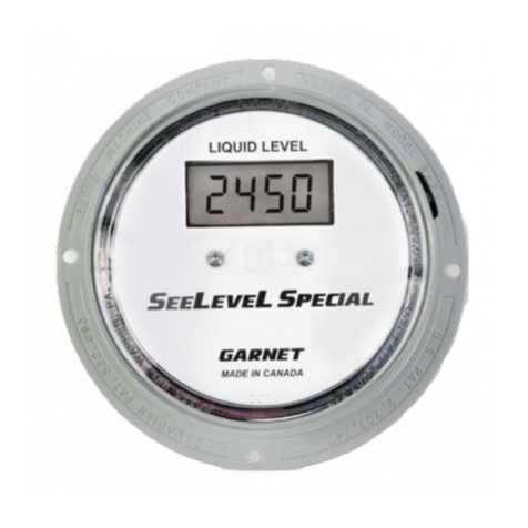
Garnet SeeLeveL Special 809-DM User manual

Printed in Canada
www.garnetinstruments.com
MODEL 809-DM MANUAL
Truck Multi-Tank Dispensing System
IMPORTANT OPERATOR INFORMATION
DATE INSTALLED: _______________________________________________________________________________
UNIT NUMBER:_________________________________________________________________________________
COMPARTMENTS: ______________________________________________________________________________
DISPLAY CALIBRATION UNITS (e.g. pints, gallons):_____________________________________________
MINIMUM TANK READOUT: ___________________________________________________________________
MAXIMUM TANK READOUT: ___________________________________________________________________
BYPASS RESET ALARM POINT (A3): ____________________________________________________________
OVERFILL HORN WARNING POINT (A2):_______________________________________________________
OVERFILL SHUTDOWN POINT (A1):____________________________________________________________
TM

Page 2 809-DM Manual
Table of Contents
CHAPTER 1 - OVERVIEW.............................................................................................3
CHAPTER 2 - GAUGE DESCRIPTION.......................................................................4
CHAPTER 3 - UNIQUE FEATURES ............................................................................6
CHAPTER 4 - DISPLAY OPERATION ........................................................................8
CHAPTER 5 - ALARM OPERATION ........................................................................ 12
CHAPTER 6 - CALIBRATION PROGRAMMING INSTRUCTIONS ................. 17
CHAPTER 7 - SERIAL INTERFACE COMMANDS................................................ 20
CHAPTER 8 - SENDER BAR OPTIONS .................................................................. 25
CHAPTER 9 - SENDER BAR LIMITS OF RESISTIVITY........................................ 26
CHAPTER 10 - INSTALLATION GUIDE .................................................................. 29
CHAPTER 11 - TROUBLESHOOTING GUIDE ...................................................... 33
CHAPTER 12 - SERVICE & WARRANTY INFORMATION................................ 35
MAIL IN WARRANTY ................................................................................................. 37
GARNET
SEELEVEL SPECIAL TM
Truck Multi Tank Dispensing System
MODEL 809-DM
809-DM Manual_v5.3 - 04-Sep-2018

Page 3
809-DM Manual
CHAPTER 1 - OVERVIEW
Congratulations on purchasing the Garnet Instruments Model
809-DM SEELEVEL SPECIAL™ Gauge for Trucks. The SEELEVEL
represents the state of the art in liquid level measurement
equipment for transport applications. The SEELEVEL is designed
for reliable, accurate level measurement of sour or sweet crude oil,
chemicals, acids, water, condensate, gasoline, or diesel fuel. The
liquid level is determined by sensing the position of a magnetic
oat using a series of reed switches arranged in a vertical sensing
bar. This technology has no moving parts except for the oat, and
can operate over a range of product temperatures from -40°C to
+90°C (-40°F to +194°F).
The 809-DM SEELEVEL has been designed to withstand the vibration
and shock encountered in mobile applications.
The 809-DM SEELEVEL can display in any units, such as inches of
level, pints, quarts, gallons, barrels, or cubic metres of volume. It
has multiple alarm relay and transistor outputs which can be used
to operate horns, lights, pumps, valves, or engines.
The 817 Truck Gauge Programmer is used to program the SEELEVEL
to read the desired calibration units. It is designed to be easily
operated by people unfamiliar with electronics or computers.
The 809-DM is designed specically for trucks with multiple
tanks (up to 6, plus up to 3 water tanks using additional 808P2
gauges) which are used to accurately dispense chemicals. Front
panel controls, remote communications, PTO sensing, and a full
complement of alarm outputs make it a complete solution for this
type of truck. Battery operation of the basic level functions allows
checking of tank levels even with the truck turned off.

Page 4 809-DM Manual
CHAPTER 2 - GAUGE DESCRIPTION
The 809-DM SeeLeveL gauge consists of six sender bars, six
donut shaped oats, ber optic interconnect cables, and a
display. Each sender bar is mounted vertically in the tank with the
oat sliding up and down around it in accordance with the uid
level. The sender bar sends the uid level information via ber
optic cable to the display, which displays the level in appropriate
units and operates the alarms and remote data transmitter. Up to
three more tanks can also be monitored using the Remote Inputs
on the 809-DM.
The oat contains magnets which activate reed switches inside the
stainless steel sender bar to indicate the level of the uid. The
activated switches are detected by the microprocessor at the top
of the bar. The microprocessor operates from a long life lithium
battery giving about 10 years of life. The level information is
relayed through the ber optic cable to the display, the ber being
used to maintain electrical isolation between the sender bar and
the display, allowing operation in ammable liquids.
The display converts the level information to volume according
to the calibration programmed into it with the 817 Truck Gauge
Programmer. The calibration can be in inches or volumetric units
such as cubic metres or barrels, and each tank can have its own
calibration. The tank level is shown on an illuminated LCD (Liquid
Crystal Display) which gives excellent visibility. The display operates
from a 10 year lithium battery, with 12 volt truck power operating
the LCD illumination, alarms, and remote communications. The
entire display is enclosed in a 6” by 6” by 4” weatherproof enclosure
which can be mounted inside or outside of the truck cab.
The 809DM system is designed for body trucks with up to 6
product tanks. It also has remote inputs to connect up to 3 other
Garnet gauge systems, which may be used for water tanks on the
same truck. The system provides remote communications via a
serial port which can be used to remotely program the amount of
product to be dispensed, as well as to be able to remotely monitor
the tank levels, alarms, and truck PTO status.
Only one tank is viewed at a time, selected by the buttons on the
front panel. However, when not dispensing, all of the tanks are
scanned to keep the alarm and remote communication information
up to date. During dispensing, only the viewed tank is monitored
to make sure that it is kept up to date as quickly as possible.

Page 5
809-DM Manual
Each tank has its own set of alarms, with each set of 6 having a
common output to operate lights, horns, engine shutdowns, or
valves. The dispense alarm can be programmed from the front
panel using the push buttons; it is used to accurately dispense
the correct amount of product by sounding a horn or shutting a
valve when the amount to be dispensed has been reached. The
rising level alarm activates if a tank level not being viewed rises
more than a few inches to alert the operator that the wrong tank
is being lled. The overll warning alarm is programmed into the
gauge with the 817 programmer, and is used to warn the operator
that the tank being lled has reached its maximum level. The
overll shutdown alarm is also programmed into the gauge with
the 817 programmer, and functions as an emergency shutdown to
prevent the tank from being overlled and causing a spill.
See Chapter 5 for details of alarm operation.
WARNING: The use of alarm points is entirely at the owner’s
risk due to the nature of connecting external horns or lights,
the reliability of external horns or lights, and the requirement
for truck power to operate them.
Installation of the gauge is straight forward, consisting of mounting
one sender bar in each of the tanks, mounting the display at a
convenient location, connecting the sender bars to the display
with the provided bre optic cable, and wiring the display to truck
power and the various alarm lights, horns, shutdowns, or valves.
Programming the calibrations and alarm points into the display
completes the installation. Any of the components can be easily
replaced for servicing. Chapter 10 describes the installation in
detail.

Page 6 809-DM Manual
CHAPTER 3 - UNIQUE FEATURES
The SeeLeveL gauge has been designed for maximum ease of
installation and servicing, and for best operational features.
The anchor at the bottom of the tank provides a shock mount for
the oat. If the sender bar needs replacement, the new sender bar
can be cut to the same length as the old so that no re-calibration
is required.
The polyethylene oat has good chemical resistance, good
esthetic appearance, and high durability due to the “give” in the
plastic. The light weight of the polyethylene allows the oat size
to be minimized while allowing it to oat on the lowest density
products.
The sender bar has no moving parts and is completely lled with
potting material to enhance reliability. The use of a digital rather
than analog sensing technique lowers power consumption to
permit battery operation, and ensures high accuracy with no drift
or degradation. To accommodate different tank sizes, the bar is
simply cut to length with a hacksaw, and the cut end sealed with a
cap to prevent moisture or product contamination. This way only
one size needs to be stocked, and a perfect t is ensured. The
sender head is very low in prole to satisfy rollover requirements;
the maximum height is less than 5 inches above the top of the
tank so that it will not protrude above the spillway. The sender bar
provides a high resolution of either 1/6” or 1/10”.
The single ber optic cable connecting the sender head to the
display can be disconnected at both ends. There is approximately
10 times as much light as is required for operation available for
the ber, so no special ber end preparation is required. The ber
ensures that even with faulty wiring into the display, no explosion
hazard can exist.
The small size of the display box also makes it easy to nd an
appropriate mounting location. The illuminated LCD ensures that
the gauge display is always visible, regardless of ambient lighting
conditions.
The use of an on-site programmer eliminates downtime waiting
for factory calibration parts, and allows easy reprogramming
should the need arise. The entire display, including decimal point,
is completely programmable to whatever units are desired. In
addition to numbers, the letters F, U, L, and E can be programmed
to provide displays such as FULL, E, etc. The alarm can be
programmed to turn either on or off to save terminals and wiring,

Page 7
809-DM Manual
and uses a relay to increase current capability, and minimize
gauge battery power drain. The user can set the dispense alarm
with front panel buttons, so that no programmer is required when
dispensing at a site.
SEESEVELSPECIAL
TANK 1HORNUP
SET
VOLUME
SHUT
TOTAL
ESCAPE
DOWNDOWN
TANK 2 TANK 3
TANK 4 TANK 5 TANK 6
CURRENT TANK VOLUME VOLUME DISPENSED
SHUT DOWN VOLUME TANK SELECTED
GENERAL MECHANICAL ASSEMBLY
ANCHOR SUPPORT
1/4” AIR LINE CONTAINING FIBER
OPTIC INTERCONNECT CABLE
TAPER ALLOWS
DEBRIS TO SLIDE
OFF FLOAT
COMPRESSION FITTING 1” COUPLER
TANK CUTAWAY
STAINLESS STEEL
SENSOR BAR
HEAD (INSTALLED HEIGHT LESS THAN 5 INCHES ABOVE THE TOP OF THE TANK
S
EE
S
EVE
L
S
PECIAL
TANK 1HORNUP
SET
VOLUME
SHUT
TOTAL
ESCAPE
DOWNDOWN
TANK 2 TANK 3
TANK 4 TANK 5 TANK 6
CURRENT TANK VOLUME VOLUME DISPENSED
SHUT DOWN VOLUME TANK SELECTED

Page 8 809-DM Manual
CHAPTER 4 - DISPLAY OPERATION
Display window description:
1. The upper left display shows the volume of product in the
selected tank. The lower right display shows the tank number
selected. When the 12 volt power is active, then the displays
are illuminated for night viewing.
2. Normally, the upper right and lower left displays are blank.
When dispensing, the upper right display shows the amount
that has been dispensed, and the lower left shows the volume
when the dispensing will be complete. During alarm events
these two displays will show the alarm information.
3. During dispense volume programming, the displays are used
for programming functions; see the alarm section for a full
description of that.
4. The lower right display also shows the alarm bypass status,
the leftmost decimal indicates a bypassed overll warning
alarm. The third decimal (xxx.x) indicates a bypassed overll
shutdown alarm. See the alarm section for full details.
Display scanning operation:
1. When not dispensing, the gauge continuously scans all of the
tanks for alarm events and to keep the remote communication
information up to date.
2. The viewed tank is the one that currently is showing its level
on the upper left display. The tank number of the viewed tank
is shown on the lower right display. To select the viewed tank,
see the next section below.
3. A scanned tank is any of the other ve tanks that are not
being viewed. The gauge will select which of the six sender
bars to receive in order to do the scan.
4. The scanning order always gives priority to the viewed tank,
with the receiving of the scanned tanks occurring in between
the receiving of the viewed tank. For example, if tank 2 is the
viewed tank, the scanning will occur as follows: 2-1-2-3-2-4-
2-5-2-6-2-1-2-3-2-4-2-5-2-6-2 and so on.
5. Since each sender bar sends out its data about every 700ms,
it can take up to 10*700ms=7 seconds to complete a scan.
However, since the bars are transmitting randomly, a typical
scan will take less time than this. If the gauge starts to receive a
sender bar when it is already part way through its transmission,

Page 9
809-DM Manual
the gauge will recognize this and wait for another complete
transmission before going to the next sender.
6. During dispensing, it is important for the gauge to focus on
the viewed tank so that it can respond as quickly as possible
when the dispensing amount has been reached. This is why
scanning is not done during dispensing.
Select a tank to view:
1. The lower right display shows the tank number currently
selected. To select another tank, press and hold the
corresponding tank button until the display changes to the
new tank number.
2. The tank buttons are illuminated by amber/orange LEDs for
night visibility. The selected tank will have the LED brightly
illuminated.
3. If the 12 volt power to the gauge is not active, then the LEDs
will not work but the tank buttons and the tank volume
information will still function.
Check the software version of the main processor:
1. Either unplug the bre optic cable from the tank being viewed,
or disconnect the ribbon cable between the display face and
the base circuit board. The display must be showing “no L” in
order to check the version.
2. Press and hold the UP and HORN buttons on the front of the
display. The display will show “rX.XX code”, where X.XX will be
a number like 5.18, which is the software code version of the
main processor.
3. Release the buttons to return to normal operation. Reconnect
the bre or ribbon cable.
4. See the section on Serial Interface Commands to nd the
software version of the remote communications processor.
How to connect and program the PTO input:
1. The PTO input senses the state of the truck PTO in order
to know when loading or dispensing is occurring. Alarm
operation is affected by PTO status, see the alarm section for
full details.

Page 10 809-DM Manual
2. The PTO status is normally detected by an air pressure switch
connected to the PTO pneumatic control line. This switch may
already be present on the truck for other purposes, such as
an indicator light, or it may need to be installed as part of the
gauge installation.
3. Normally the PTO switch will have one side connected to
ground, and the other side connected to the PTO input on the
gauge. If one side of the PTO switch is connected to 12 volts
instead of ground, then an external load such as an indicator
light must be used. See the appropriate wiring diagram for
details.
4. There are two parameters that must be set in order for the
PTO sensing to work properly, the PTO pull-up resistor and
the PTO polarity.
5. The PTO pull-up resistor must be turned on if the air pressure
switch has one side connected to ground and the other side
is not connected to a light bulb or any other load. If there is
a light to indicate PTO status from the switch, then the pull-
up can be turned off. To set the pull-up, connect the 809DM
Serial Port Tester to the connectors in the base of the gauge
display and turn it on. Press the PULLUP PTO I/P button and
then ENTER to check the current status of the pull-up. To
change it, press the same button and then either 0 or 1 (as
shown on the Tester screen) to congure the pull-up.
6. The PTO polarity must be set to match the type of switch
used to detect the air pressure. If the switch has one side
connected to ground and closes when the PTO is engaged,
then the input will be grounded when the PTO is engaged
(e=0). Conversely, if the switch opens during engagement,
then the input will be grounded when the PTO is disengaged
(e=1). If one side of the switch is connected to 12 volts, then
this will reverse the polarity of the switch.
7. To check the polarity, connect the 809DM Serial Port Tester to
the connectors in the base of the gauge display and turn it on.
Verify that the PTO is either engaged or disengaged. Then
press the PTO STATUS button on the Tester and then ENTER,
the Tester screen will then show what the gauge thinks is the
PTO status. If this is incorrect, then press the SHIFT and PTO
I/P POLAR buttons at the same time on the Tester, then ENTER
to show the current polarity setting. To change the setting,
press the SHIFT and PTO I/P POLAR buttons again followed
by either 0 or 1 as required. Then press ENTER to properly
congure the polarity.
8. Verify that the gauge now is properly sensing the PTO polarity
using the PTO STATUS button on the Tester.

Page 11
809-DM Manual
Program the 809-DM gauge for the correct number of tanks:
1. The 809-DM is xed at six tanks for the main processor
software version 5.18 and above.
2. Previous versions were programmable for less than six tanks,
but this feature was removed since all applications had six
tanks. This simplied installation and programming, and
reduced that possibility of errors.

Page 12 809-DM Manual
CHAPTER 5 - ALARM OPERATION
There are are four alarm sources which operate three alarm
outputs:
1. A dispense alarm which operates the dispense alarm output
relay. This relay has normally open contacts that close when
the alarm is active. The contacts can be wired to 12 volts or
ground to activate a sounder, horn, light, or valve control. The
contacts are rated at 20 amps.
2. A rising level alarm and an overll warning alarm which share
a warning alarm transistor output. This transistor output
provides a connection to ground when either alarm is active.
It can also be connected to a horn or light. The transistor is
rated at 1 amp.
3. An overll shutdown alarm which operates the overll
shutdown output relay. This relay has normally open contacts
that break the circuit when the alarm is active. These contacts
can be wired to 12 volts or ground to perform a shut down
function. The contacts are rated at 20 amps.
The application of these outputs is up to the user, any one of them
may be ignored or connected to external controls.
The dispense alarm is used to monitor how much product is being
dispensed by the operator. The desired amount to be dispensed
is entered into the gauge with the front panel buttons, and when
the tank level drops to the point where that amount has been
dispensed from the tank the dispense alarm will be triggered. This
alerts the operator to stop dispensing at that point. The dispense
alarm output relay is usually connected to a sounder and/or a light
to provide audible and/or visual indication of the alarm. Operation
of the dispense alarm is independent of PTO status.
To set the amount to dispense, press the UP and DOWN buttons
at the same time. Within 1 second the displays will show “SEt
ALAr”, release the buttons and the top right display will change
to 0 showing the amount to be dispensed, and the bottom left
display will show the trip point, which will read the current level
right now.
Use the UP button to increase the amount to be dispensed, shown
on the top right display. The bottom left display will show the
changing alarm trip point. If you go too far, use the DOWN button
to reduce the dispense amount. Press and hold the UP or DOWN

Page 13
809-DM Manual
button to go fast. When the desired dispensing amount is shown
in the top right display, press the HORN button to store the value.
The displays will show “ALAr Stor” while the button is pressed to
show that the value has been stored. If no button is pressed for
1 minute the system will time out and exit and no values will be
stored. If you want to quit without saving anything, press the
TOTAL/ESCAPE button. If the amount to be dispensed is set to
zero, the display will show “ALAr CLr” when the HORN button is
pressed and the dispense alarm will be cleared.
To check the settings as the product is dispensing, press the TOTAL
button, the bottom left display will show the remaining amount
still to be dispensed, the top right shows the total amount that
was originally set, and the top left shows the starting volume.
When the amount to be dispensed has been reached, the current
tank volume will match the shut down volume, and the volume
dispensed will show the amount that was originally programmed.
Pressing the TOTAL button at this point will cause the lower
left display to show “done”. The dispense alarm will be tripped
which lights the HORN LED and energizes the dispense output
relay, activating the sounder or light connected to the relay. This
indicates to the operator that the dispensing valve should be
closed immediately. If dispensing is continued past this point, the
alarm will continue to be active and the volume dispensed will
continue to increase. The lower left display will continue to show
“done” when the TOTAL button is pressed.
To deactivate the alarm when dispensing is complete, press the
HORN button. This will turn off the dispense relay output and the
HORN LED. The upper right display will show “done” while the
HORN button is pressed. The displays will still show the volume
dispensed and the shut down volume until a new dispense amount
is programmed. Any dispense settings will be cleared when a
different tank is selected.
The rising level alarm is used to alert the operator to improper
tank loading or lling which causes a rise in level in a tank which is
not being currently viewed. The gauge continually scans the level
of all of the tanks whenever the system is not in dispensing mode.
If the level of any tank not currently displayed rises by more than
30 increments (5 inches in 1/6” mode or 3 inches in 1/10” mode),
then the rising level alarm is triggered. The rising level alarm does
not function for the viewed tank.
When a tank is scanned, the minimum level measured is stored
as the starting point for the rising level calculation. Every time
a scan occurs (typically every few seconds) the measured level is

Page 14 809-DM Manual
compared with the stored level. If the new level is lower than the
stored amount, then the new level is stored as the starting point.
If the new level is the same as the stored level, nothing further
is done. If the new level is higher than the stored level, and if
the scanned tank is one not being viewed, then the difference is
calculated to see if it exceeds 30 increments.
When the level has risen more than 30 increments, the alarm is
triggered. This turns on the HORN LED and activates the warning
alarm output which sounds the warning horn or lights the warning
light. The display will show the tank number in alarm in the upper
right hand display (e.g. “tAn3”) and “rISE” in the lower left display.
If there are multiple alarms occurring, then the display will show
each alarm indication in turn. When the PTO is disengaged, the
display and HORN LED will show the alarm but the alarm output
will be off. This prevents slosh from activating the warning horn
during driving.
To acknowledge (bypass) the alarm, the tank that is alarming
must be rst selected as the viewed tank using the corresponding
tank button. Then the HORN button must be pressed, this will
deactivate the warning alarm output and reset the rising level
alarm. While the HORN button is pressed the upper left display will
show “bYPS”. The level that is shown when bypassed will become
the new starting point for subsequent rising level calculations. If
multiple tanks are in alarm at the same time, they all must be
bypassed before the alarm is deactivated.
The overll warning alarm complements the rising level alarm.
It shares the same output and only operates on the tank being
viewed. The trip point of the alarm is set using the 817 Truck
Gauge Programmer as A2, with the bypass reset point as A3. This
alarm is normally used during tank lling to alert the operator that
the tank is at the full point. It will also serve as a warning that the
tank has been unintentionally lled.
When the tank level is below the trip point the alarm is off and the
warning alarm output is not active. When the tank level rises so
that it is equal to or above the trip point, the alarm is activated,
which turns on the HORN LED and activates the warning alarm
output. There is no additional indication on the display when the
alarm is triggered. When the PTO is disengaged, the HORN LED
will show the alarm but the alarm output will be off. This prevents
slosh from activating the warning horn during driving.
To bypass the alarm, press the HORN button, this will turn off
the HORN LED and the alarm output. While the HORN button is
pressed the upper left display will show “bYPS”. The left decimal

Page 15
809-DM Manual
(t.An1) on the lower right display will turn on to indicate that there
is a bypassed overll warning alarm for that tank. The bypass
is automatically removed when the tank level drops below the
A3 set point, which is normally set near the minimum operating
tank level. This automatic reset of the bypass ensures the alarm
is active the next time the tank is lled. The bypass can also be
manually removed by pressing the TOTAL and HORN buttons at
the same time.
The overll shutdown alarm is used as an emergency shutdown
of the loading process to prevent tank overlling and spills. The
shutdown alarm works on all tanks, whether viewed or scanned.
The trip point of the alarm is set using the 817 Truck Gauge
Programmer as A1, with the bypass reset point as A3. The
shutdown point is always above the warning point. This alarm is a
backup used during tank lling to shut down the loading process
if the operator is unable to shut off loading. In addition, if a fault
occurs which lls any of the tanks to a dangerously high level,
the alarm will provide an emergency shutdown. The shutdown is
normally used to turn off the truck engine or loading pump.
When the tank level is below the trip point the alarm is off and the
shutdown alarm output allows the truck engine or loading pump
to operate. The green LED below SHUT DOWN button will be on.
When the tank level rises so that it is equal to or above the trip
point, the alarm is activated, which turns off the green LED, turns
on the red SHUT DOWN LED and turns off the truck engine or
loading pump. The upper right display shows the tank number
that is in shutdown alarm (whether the viewed tank or a scanned
tank) and the lower left display shows “FULL”. If there are multiple
tanks in either shutdown or rising level alarm, then the display will
show each alarm indication in turn. When the PTO is disengaged,
the display will show the alarm but the green LED will be on and
the alarm output will continue to allow engine or pump operation.
This prevents slosh from shutting down the engine during driving.
Only the viewed tank can be bypassed. Consequently, a scanned
tank in alarm must be selected as the viewed tank using the
corresponding tank button. To bypass, press the SHUT DOWN
button, this will turn off the SHUT DOWN LED, turn on the green
LED, and allow the engine or pump to be restarted. While the
SHUT DOWN button is pressed the upper left display will show
“bYPS”. The right decimal (tAn.1) on the lower right display will
turn on to indicate that there is a bypassed overll shutdown
alarm for that tank. If both the warning and shutdown alarms
are bypassed then both decimals will be on (t.An.1). The bypass
is automatically removed when the tank level drops below the A3
set point, which is normally set near the minimum operating tank

Page 16 809-DM Manual
level. This automatic reset of the bypass ensures the alarm is active
the next time the tank is lled. The bypass can also be manually
removed by pressing the TOTAL and SHUT DOWN buttons at
the same time. If multiple tanks are in alarm, they all must be
bypassed before the alarm is turned off.
To program the overll warning and shutdown alarm points:
1. Using the 817 programmer, set alarm 1 for the overll
shutdown point, alarm 2 for the overll warning point, and
alarm 3 for the bypass removal (minimum tank level) point.
Alarm 1 must be higher than alarm 2, and alarm 2 must be
higher than alarm 3.
2. All three of the alarms must be programmed as shutdown.
3. A3 should be set a few inches above the normal minimum tank
operating level. This way tank sloshing will not inadvertently
remove the bypasses and activate an alarm, and yet ensure
that the bypasses are removed prior to lling during normal
tank operation.

Page 17
809-DM Manual
CHAPTER 6 - CALIBRATION PROGRAMMING INSTRUCTIONS
The 809-DM must have the volume calibration programmed
into it for each of the tanks. The 817 Truck Gauge Programmer
is used to program calibrations and to set offsets. When the
programming plug is connected to the gauge, the gauge display
will show “prog” within a couple of seconds. Do not start
programming the gauge until “prog” is shown. After the plug
has been removed, the gauge display will show “donE” for a
moment. The tank number to be programmed must be selected
before plugging in the programmer, and the programmer must be
unplugged before the next tank can be selected.
Program the 809-DM gauge display into inches:
1. Turn on the programmer.
2. Make sure the inch mode is correct.
3. Select a memory location with MEM LOC.
4. Press the INCH MEM (SHIFT – 1) button to put inches into the
memory. If the inches are already in memory from a previous
calibration, it is not necessary to do it again, but make sure
that they are the correct inches (1/6 or 1/10).
5. Select the tank number to be programmed using the tank
buttons on the front panel. Each tank needs to be programmed
individually.
6. Make sure that the bers from the sender bars are connected
to the opto connectors on the base PCB, and that the ribbon
cable is connected between the display face and the base PCB.
Plug the programmer plug into the display face, the display
should show “prog” and the tank number being programmed.
7. Press the BAR button. The INCHES display on the programmer
should show some inch reading, if it shows “no L” or “bad L’
check the ber connection and the bar mode (1/6 or 1/10
inch). NOTE: The black ber optic cable connector MUST be
shaded from direct sunlight. See the 817 User Manual for
further information.
8. Measure the distance from the bottom of the tank to the
middle of the oat, this is the bottom reading. Use the
OFFSET buttons on the programmer to obtain this reading
on the CALIBRATION display. NOTE: The calibration offset is
carried over when memory locations are changed.
9. Press the PROG button to transfer the calibration to the
gauge.

Page 18 809-DM Manual
10. When the operation is complete, unplug the programmer
from the gauge and verify gauge operation.
11. To program the next tank, repeat steps 5 to 10. Note that
the programmer plug must be disconnected to select a tank,
the tank buttons will not respond when the programmer is
plugged in.
Copy one 809-DM gauge display to another (can also copy
from an 808P2 or 810PS/810PS2):
1. Turn on the programmer.
2. Make sure the inch mode is correct.
3. Select a memory location with MEM LOC.
4. Select the tank to be copied to or from using the tank buttons
on the front panel.
5. Plug the programmer plug into the gauge display to be copied
from. Press the COPY button to copy the gauge calibration
into memory.
6. When the operation is complete, unplug the programmer plug
from the rst gauge and plug it into the gauge display to be
copied to. Press the PROG button to transfer the calibration
to the second gauge.
7. When the operation is complete, unplug the programmer
from the gauge and verify gauge operation.
8. To program the next tank, repeat steps 4 to 7. Note that the
programmer plug must be disconnected to select a tank,
the tank buttons will not respond when the programmer is
plugged in.
Program a 809-DM gauge display from a table of calibration
values:
1. Obtain a table of inches versus volume
2. Turn on the programmer.
3. Make sure the inch mode is correct.
4. Select a memory location with MEM LOC.
5. Press the CLEAR MEM button to erase any previous
calibration.
6. Starting at the 0 inch value of volume calibration, use the 0
to decimal, E, F, L, U, or BL buttons on the keypad to enter
the calibration. Press the ENTER button to store the value
in memory. When ENTER is pressed, the inches will go to

Page 19
809-DM Manual
the next value. If you make a mistake, use the BACK button
to erase the entry, or if ENTER has already been pressed,
use INCHES to go back to that inch value and re-enter
the correct value. If more than 4 numbers are entered the
previous ones will scroll off the left of the display. If ENTER is
pressed before any numbers, nothing will happen.
7. After the table has been entered, use the INCHES buttons
to review the table to make sure it is correct. If a calibration
value is incorrect, simply re-enter it and press ENTER.
8. Continue with the same procedure as in Program the 809-
DM gauge display into inches from step 5. When setting
the bottom reading, use the calibration table to look up the
volume corresponding to the distance to the middle of the
oat. Use the OFFSET buttons to obtain this reading on the
CALIBRATION display.
Program a 809-DM gauge display from a table stored in
memory:
1. Turn on the programmer.
2. Make sure the inch mode is correct.
3. Select the desired memory location with MEM LOC.
4. After the table has been entered, use the INCHES buttons
to review the table to make sure it is correct. If a calibration
value is incorrect, simply re-enter it and press ENTER.
5. Continue with the same procedure as in Program the 809-
DM gauge display into inches from step 5. When setting
the bottom reading, use the calibration table to look up the
volume corresponding to the distance to the middle of the
oat. Use the OFFSET buttons to obtain this reading on the
CALIBRATION display.

Page 20 809-DM Manual
CHAPTER 7 - SERIAL INTERFACE COMMANDS
The following section describes the dened 809-DM serial
commands. The serial data requests are ASCII data strings.
Throughout this section <CR> represents a single carriage return
character (hexadecimal 0x0D). In this section Red text represents
serial data being received by the 809-DM. Blue text represents
serial data being transmitted from the 809-DM. Either uppercase
or lowercase characters can be used, the response will be in the
case that is used to make the request.
To communicate with the gauge for testing purposes, the 809DM
Serial Port Tester can be used. It has all of the serial commands
preprogrammed for easy reference. Press the corresponding
button (or SHIFT and the button at the same time) followed by
ENTER to query the current setting of any of the parameters. Press
the button followed by the number sequence as indicated on the
Tester screen, followed by ENTER to set any of the parameters. The
Tester will interpret the gauge response with English phrases to
make it easy to know what the settings are.
PTO change
During normal operations, a change of PTO status causes the 809-
DM to send out a comma separated list of values corresponding
to the PTO status followed by the number of channels being
monitored. The transmit is done after a programmable delay.
p,E,11.16,79.00, 0.00, 0.00, 0.00, 0.00<CR>
The next example shows the PTO disengaged and only two
channels being monitored.
p,D,11.16,79.00<CR>
The next example shows the PTO engaged and all six compartments
having invalid data.
p,E,NOSIG,NOSIG,NOSIG,NOSIG,NOSIG,NOSIG<CR>
The level reading will always be ve characters including the
decimal place. If no decimal place is present a space character will
pad the least signicant byte. NOSIG shows no valid level data.
ERROR shows level data error.
Set PTO conguration
There are four items to congure:
1. Resistor pullup on or off.
2. PTO engagement polarity high or low.
Table of contents
Other Garnet Measuring Instrument manuals

Garnet
Garnet SeeLevel II User manual

Garnet
Garnet PC-732G User manual

Garnet
Garnet SeeLeveL II 709-RVC User manual

Garnet
Garnet SeeLevel I 705 Series User manual

Garnet
Garnet SeeLevel II 900-D4S Single User manual

Garnet
Garnet SeeLevel II User manual

Garnet
Garnet SeeLeveL II 709-P3 User manual

Garnet
Garnet 900D6 DUAL User manual

Garnet
Garnet Seelevel Special 808P2 Operating manual

Garnet
Garnet SeeLeveL II 709-RVC PM User manual