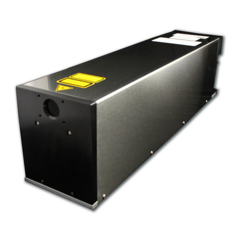
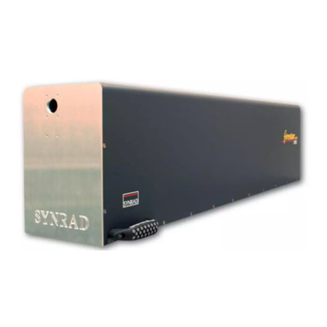
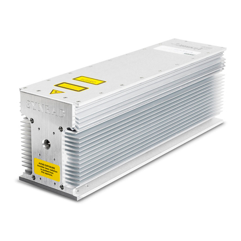
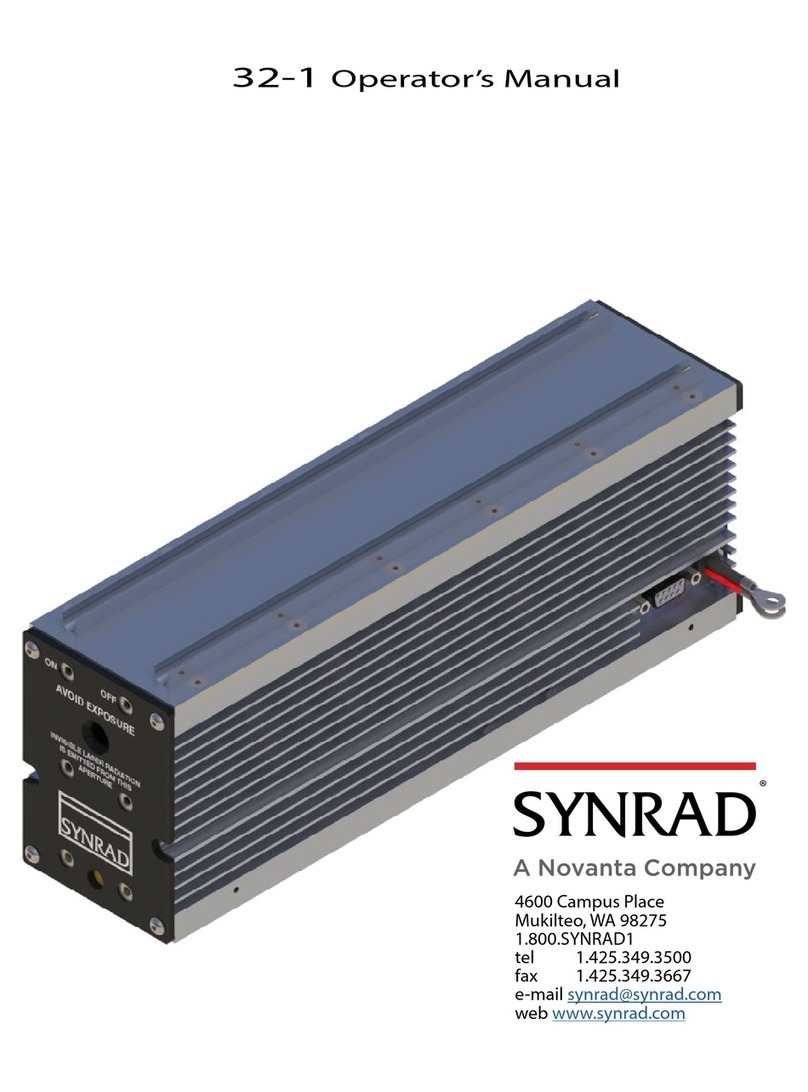
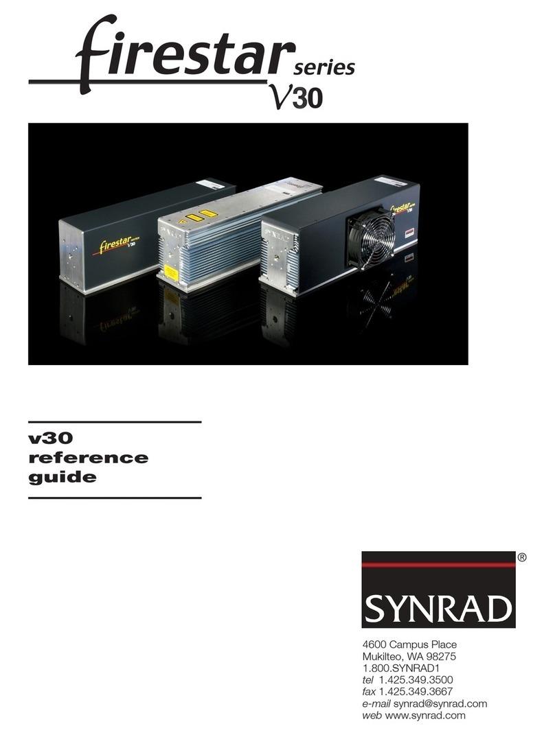
Synrad Firestar Series User manual

4600 Campus Place
Mukilteo, WA 98275
1.800.SYNRAD1
tel 1.425.349.3500
fax 1.425.349.3667
e-mail [email protected]om
web www.synrad.com

OEM v30
Operator’s Manual
Version 2
SYNRAD©is a registered trademark of Novanta Corporation. ©Novanta Corporation
2019. All Rights Reserved. No reproduction without written authorization.
DATE: March 2019

table of contents
i
SYNRAD OEM v30 Operator’s Manual Version 2
Getting Started 1
Laser Safety
Operation 2
Hazard information.....................................................................................................1
Terms...................................................................................................................................................1
General hazards...............................................................................................................................1
Other hazards...................................................................................................................................3
Disposal..............................................................................................................................................3
Additional laser safety information..........................................................................................3
Firestar OEM v30 label locations............................................................................4
Agency compliance....................................................................................................5
Center for Devices and Radiological Health (CDRH) requirements..............................5
Federal Communications Commission (FCC) requirements...........................................5
European Union (EU) requirements.........................................................................................6
Declaration of Conformity .......................................................................................9
Introduction ..................................................................................................................1-2
Firestar nomenclature...................................................................................................................1-2
Model numbers...............................................................................................................................1-2
Unpacking......................................................................................................................1-3
Incoming inspection .....................................................................................................................1-3
Packaging guidelines ....................................................................................................................1-3
Inventory ........................................................................................................................1-4
Contents description.....................................................................................................................1-5
Mounting........................................................................................................................1-6
Connecting....................................................................................................................1-7
Water-cooled connections..........................................................................................................1-7
Air-cooled connections ................................................................................................................1-11
Electrical connections...................................................................................................................1-12
Control connections ......................................................................................................................1-13
Controls and indicators.............................................................................................2-2
OEM v30 front panel......................................................................................................................2-2
OEM v30 rear panel........................................................................................................................2-3
Initial start-up ...............................................................................................................2-4
Status LEDs........................................................................................................................................2-4
With a UC-2000 Controller...........................................................................................................2-5
Without a UC-2000 Controller....................................................................................................2-6

table of contents
ii SYNRAD OEM v30 Operator’s Manual Version 2
Index
Technical overview .....................................................................................................3-2
OEM v30 laser ................................................................................................................................3-2
Optical setup....................................................................................................................................3-3
Controlling laser power.............................................................................................3-5
Control signals.................................................................................................................................3-5
Operating modes............................................................................................................................3-7
Interface connections................................................................................................3-9
Interface A (DB-9) connector......................................................................................................3-9
Interface B (RJ45) connector.......................................................................................................3-15
OEM v30 general specications.............................................................................3-21
OEM v30 package outline drawings.....................................................................3-22
OEM v30 packaging instructions...........................................................................3-25
Maintenance/Troubleshooting 4
Technical Reference 3
Maintenance .................................................................................................................4-2
Disabling the v30 laser .................................................................................................................4-2
Daily inspections.............................................................................................................................4-2
Storage/shipping............................................................................................................................4-3
Cleaning optical components....................................................................................................4-3
Troubleshooting ..........................................................................................................4-6
Introduction......................................................................................................................................4-6
Operational owchart...................................................................................................................4-7
LED/output signal status .............................................................................................................4-8
Laser fault indications...................................................................................................................4-12
Resetting faults................................................................................................................................4-12
Laser troubleshooting...................................................................................................................4-13
Beam delivery optics .....................................................................................................................4-17

table of contents
iii
SYNRAD OEM v30 Operator’s Manual Version 2
List of Figures
Figure 1 Firestar OEM v30 hazard label and CE label locations ...........4
Figure 2 European compliance mark ............................................................8
Figure 1-1 Firestar v30 shipping box contents ..............................................1-4
Figure 1-2 OEM v30 mounting locations (1/4-20 fastener
locations shown) .................................................................................1-6
Figure 1-3 OEM v30 cooling connections........................................................1-10
Figure 1-4 Recommended v30 cooling fan locations - free-space
cooling ....................................................................................................1-11
Figure 1-5 Recommended fan shroud design - rear cooling....................1-12
Figure 1-6 PS-2 (Emerson iMP4) power supply..............................................1-13
Figure 2-1 OEM v30 front panel controls and indicators ...........................2-2
Figure 2-2 OEM v30 rear panel controls and indicators .............................2-3
Figure 3-1 OEM v30 beam characteristics .......................................................3-3
Figure 3-2 Representative OEM v30 waveforms ...........................................3-6
Figure 3-3 PWM Command signal waveform.................................................3-7
Figure 3-4 Interface A (DB-9) connector pinouts..........................................3-9
Figure 3-5 DB-9 input equivalent schematic..................................................3-11
Figure 3-6 OEM v30 powered Laser Enable circuit.......................................3-12
Figure 3-7 Customer powered Laser Enable circuit .....................................3-13
Figure 3-8 PLC switched Laser Enable circuit.................................................3-13
Figure 3-9 DB-9 output equivalent schematic...............................................3-14
Figure 3-10 Lase Indicator output to PLC input...............................................3-15
Figure 3-11 Interface B (RJ45) connector pinouts...........................................3-15
Figure 3-12 RJ45 input equivalent schematic ..................................................3-17
Figure 3-13 Customer powered Laser Enable circuit .....................................3-18
Figure 3-14 PLC switched Laser Enable circuit.................................................3-19
Figure 3-15 RJ45 output equivalent schematic ...............................................3-20
Figure 3-16 Laser OK output to PLC input .........................................................3-20
Figure 3-17 OEM v30 air-cooled package outline and mounting
dimensions............................................................................................3-22
Figure 3-18 OEM v30 fan-cooled package outline and mounting
dimensions............................................................................................3-23
Figure 3-19 OEM v30 water-cooled package outline and mounting
dimensions............................................................................................3-24
Figure 3-20 OEM v30 air-cooled packaging instructions ............................3-25
Figure 3-21 OEM v30 fan-/water-cooled and pre-aligned packaging
instructions............................................................................................3-26

table of contents
iv SYNRAD OEM v30 Operator’s Manual Version 2
List of Figures (cont.)
Figure 4-1 Operational owchart .......................................................................4-7
Figure 4-2 DB-9 Quick Start Plug wiring diagram.........................................4-14

table of contents
v
SYNRAD OEM v30 Operator’s Manual Version 2
List of Tables
Table 1 Class 4 safety features........................................................................7
Table 2 European Union Directives..............................................................8
Table 1-1 Ship kit contents..................................................................................1-4
Table 1-2 Dew point temperatures ..................................................................1-9
Table 3-1 Assist gas purity specications.......................................................3-4
Table 3-2 PWM Command signal levels .........................................................3-7
Table 3-3 Interface A (DB-9) pin descriptions...............................................3-10
Table 3-4 DB-9 input circuit specications....................................................3-12
Table 3-5 DB-9 output circuit specications.................................................3-14
Table 3-6 Interface B (RJ45) pin descriptions ...............................................3-16
Table 3-7 RJ45 input circuit specications ....................................................3-18
Table 3-8 RJ45 output circuit specications .................................................3-19
Table 3-9 OEM v30 general specications.....................................................3-21
Table 4-1 Required cleaning materials ...........................................................4-4
Table 4-2 Status LED and Interface A (DB-9) output signal
overview.................................................................................................4-8
Table 4-3 Normal operating condition ...........................................................4-8
Table 4-4 Laser Enable input not connected................................................4-9
Table 4-5 Over Temperature fault.....................................................................4-9
Table 4-6 DC Voltage fault...................................................................................4-9
Table 4-7 PWM Sense/Control Board fault ....................................................4-10
Table 4-8 Status LED and Interface B (RJ45) output signal
overview.................................................................................................4-10
Table 4-9 Normal operating condition ...........................................................4-10
Table 4-10 Laser Enable input not connected................................................4-11
Table 4-11 Over Temperature fault.....................................................................4-11
Table 4-12 DC Voltage fault...................................................................................4-11
Table 4-13 PWM Sense/Control Board fault ....................................................4-12
Table 4-14 Laser fault codes..................................................................................4-12

vi SYNRAD OEM v30 Operator’s Manual Version 2
Trademark/copyright information
SYNRAD and Firestar are registered trademarks of SYNRAD
All other trademarks or registered trademarks are the property of their respective owners.
© 2019 by SYNRAD
All rights reserved.

vii
SYNRAD OEM v30 Operator’s Manual Version 2
Warranty information
This is to certify that v30 lasers are guaranteed by SYNRAD to be free of all defects in materials and
workmanship for a period of one year from the date of purchase. This warranty does not apply to any
defect caused by negligence, misuse (including environmental factors), accident, alteration, or im-
proper maintenance. We request that you examine each shipment within 10 days of receipt and inform
SYNRAD of any shortage or damage. If no discrepancies are reported, SYNRAD shall assume the ship-
ment was delivered complete and defect-free.
If, within one year from the date of purchase, any part of the v30 laser should fail to operate, contact
the SYNRAD Customer Service department at 1.800.SYNRAD1 (outside the U.S. call 1.425.349.3500)
and report the problem. When calling for support, please be prepared to provide the date of purchase,
model number and serial number of the unit, and a brief description of the problem. When returning a
unit for service, a Return Authorization (RA) number is required; this number must be clearly marked on
the outside of the shipping container in order for the unit to be properly processed. If replacement parts
are sent to you, then you are required to send the failed parts back to SYNRAD for evaluation unless
otherwise instructed.
If your v30 laser fails within the rst 45 days after purchase, SYNRAD will pay all shipping charges to and
from SYNRAD when shipped as specied by SYNRAD Customer Service. After the rst 45 days, SYNRAD
will continue to pay for the costs of shipping the repaired unit or replacement parts back to the cus-
tomer from SYNRAD. The customer, however, will be responsible for shipping charges incurred when
sending the failed unit or parts back to SYNRAD or a SYNRAD Authorized Distributor. In order to main-
tain your product warranty and to ensure the safe and ecient operation of your Firestar v30 laser, only
authorized SYNRAD replacement parts can be used. This warranty is void if any parts other than those
provided by SYNRAD are used.
SYNRAD and SYNRAD Authorized Distributors have the sole authority to make warranty statements
regarding SYNRAD products. SYNRAD and its Authorized Distributors neither assumes nor authorizes
any representative or other person to assume for us any other warranties in connection with the sale,
service, or shipment of our products. SYNRAD reserves the right to make changes and improvements
in the design of our products at any time without incurring any obligation to make equivalent changes
in products previously manufactured or shipped. Buyer agrees to hold SYNRAD harmless from any and
all damages, costs, and expenses relating to any claim arising from the design, manufacture, or use of
the product, or arising from a claim that such product furnished Buyer by SYNRAD, or the use thereof,
infringes upon any Patent, foreign or domestic.

viii SYNRAD OEM v30 Operator’s Manual Version 2
Service & support information
SYNRAD©worldwide headquarters are located north of Seattle in Mukilteo, Washing-
ton. U.S.A. Our mailing address is:
SYNRAD
4600 Campus Place
Mukilteo, WA 98275
U.S.A.
Phone us at: 1.800.SYNRAD1 (1.800.796.7231)
Outside the U.S.: +1.425.349.3500
Fax: +1.425.349.3667
web: www.synrad.com
E-mail: [email protected]
Sales and Applications
SYNRAD Regional Sales Managers work with customers to identify and develop the
best CO2laser solution for a given application. Because they are familiar with you and
your laser application, use them as a rst point of contact when questions arise. Re-
gional Sales Managers also serve as the liaison between you and our Applications Lab
in processing material samples per your specications. To speak to the Regional Sales
Manager in your area, call SYNRAD at 1.800.SYNRAD1.
Customer Service
For assistance with order or delivery status, service status, or to obtain a Return Au-
thorization (RA) number, contact SYNRAD at 1.800.SYNRAD1 and ask to speak to a
Customer Service representative, or you can email us by sending a message to customer-
Technical Support
SYNRAD Regional Sales Managers are able to answer many technical questions regard-
ing the installation, use, troubleshooting, and maintenance of our products. In some
cases, they may transfer your call to a Laser, Marking Head, or Software Support Spe-
cialist. You may also e-mail questions to the Technical Support Group by sending your
Reference materials
Your Regional Sales Manager can provide reference materials including Outline &
Mounting drawings, Operator’s Manuals, Technical Bulletins, and Application Newslet-
ters. Most of these materials are also available directly from SYNRAD web site at http://
www.synrad.com.

ix
SYNRAD OEM v30 Operator’s Manual Version 2
EU headquarters
For assistance in Europe, contact SYNRAD©European subsidiary, Synrad Europe, at:
©Novanta Distribution (USD) GmbH
Parkring 57-59
85748 Garching bei München, Germany
Phone:+49-89-31707-0
web: www.synrad.com
e-mail: EMEA-[email protected]

1
getting started
1
SYNRAD OEM v30 Operator’s Manual Version 2
Use information in this chapter to prepare your OEM v30 laser for operation. The order
of information presented in this chapter is the same as the order of tasks that you will
need to perform. The best way to get your laser ready for operation is to start at Unpack-
ing and work your way through Connecting.
This chapter contains the following information:
■Introduction – introduces the OEM v30 laser, lists important features, and describes
Firestar nomenclature.
■Unpacking – provides important information about shipping your OEM v30 laser.
■Inventory – displays and describes all components shipped with your laser.
■Mounting – describes how to attach the OEM v30 laser to a mounting surface.
■Connecting – explains how to cool the laser and connect both power and control
cables.

getting started
2SSYNRAD OEM v30 Operator’s Manual Version 2
Introduction
The Introduction section includes subsections:
■Firestar nomenclature
■Model numbers
The Firestar®v30 laser is designed to provide OEMs a compact, cost-eective 30 W laser package. Al-
though the OEM v30 is part of the Firestar family of lasers, its user interface diers signicantly from the
standard Firestar interface design. With the exception of the optoisolated PWM input, PWM Positive, all
OEM v30 input and output signals operate at 5V logic levels to ensure compatibility and ease of installa-
tion when retrotting the Firestar v30 into existing 30 W laser systems. The OEM v30 control board also
diers from other Firestar v-Series models in that it does not incorporate a built-in tickle generator—users
should provide a 5 kHz, 1 µs tickle pulse between applied PWM signals.
Important Note: Firestar OEM v30SxG models do not include a ve-second delay function. This
means a tickle signal can be applied immediately after the Laser Enable input is
activated, eectively eliminating the delay on laser power-up or interlock activa-
tion. See Controlling laser power in the Technical Reference chapter for tickle signal
specications and recommended duration prior to lasing.
As with other laser safety requirements, the OEM or system integrator is solely
responsible for designing the system to incorporate a ve-second delay and any other
controls required by relevant laser safety standards for Class 4 laser devices.
Note: Although the OEM v30 is part of the Firestar family of lasers, its user interface diers signicantly
from the standard Firestar interface design. See the Interface connections section in theTechnical
Reference chapter for details.
The OEM v30 laser is available in either air-cooled (SAG) fan-cooled (SFG), or water-cooled (SWG)
congurations
The Firestar OEM v30 laser is an OEM product intended for incorporation as a component in a laser pro-
cessing system and as such does not comply with 21 CFR, Subchapter J or EN 60825-1 without additional
safeguards.
Firestar nomenclature
Firestar lasers are divided into two distinct functional categories: Keyswitch and OEM models. OEM lasers,
like the OEM v30, do not incorporate keyswitch or shutter functions required by CDRH and EN 60825-1
regulations because they are designed as components for integration into larger processing systems by the
Original Equipment Manufacturer (OEM) or System Integrator who bears full responsibility for meeting
the appropriate laser safety requirements for systems incorporating Class 4 lasers.
Model numbers
The last three characters in the Firestar model number serve to designate the functional category, cool-
ing method, and model version. The functional category is indicated by either a“K” for Keyswitch or “S”
(Switch-less) for OEM models. The next letter indicates the cooling method: “W” for water-cooled units,
“F”for fan-cooled units, and“A”for air-cooled lasers (where the customer must provide the proper cooling
via fans or blowers). The last letter in the model number indicates the current model version beginning
with “B”. For example, the model number FSV30SAG designates the Firestar v30 laser as an OEM, air-
cooled,“G”version unit.

getting started
3
SYNRAD OEM v30 Operator’s Manual Version 2
Unpacking
The Unpacking section includes subsections:
■Incoming inspection
■Packaging guidelines
Incoming inspection
Upon arrival, inspect all shipping containers for signs of damage. If you discover shipping damage,
document the damage (photographically if possible), then immediately notify the shipping carrier and
SYNRAD, Inc.
The shipping carrier is responsible for any damage occurring during transportation from SYNRAD, Inc. to
your receiving dock.
Packaging guidelines
■To prevent equipment damage or loss of smaller components, use care when removing packaging
materials.
■After unpacking, review the Inventory section and verify that all components are on hand.
■Save all shipping containers and packaging materials, including covers and plugs. Use these special-
ized packing materials when shipping the laser to another location.
■When packing a laser for shipment, be sure to remove all accessory items not originally attached to
the laser including beam delivery components, connectors, etc.
■Refer to the Firestar v30 packaging instructions drawings in theTechnical Reference chapter for details
on packaging the laser using SYNRAD-supplied shipping materials.
■When shipping water-cooled lasers, remember to drain all cooling water from the laser and then cap
open ttings to prevent debris from entering the coolant path.

getting started
4SSYNRAD OEM v30 Operator’s Manual Version 2
Inventory
Figure 1-1 Firestar v30 shipping box contents
Table 1-1 lists items included in the Firestar v30 ship kit.
Table 1-1 Ship kit contents
Shipping Box Contents Qty Shipping Box Contents Qty
SYNRAD Firestar OEM v30 Laser ....................1 Mounting Bolts ....................................................3
SYNRAD CO2Lasers Manual CD......................1 Spare Fuse..............................................................2
Quick Start Plug (except SA models)............1 Final Test Report (not shown).........................1
Cooling Tubing (water-cooled only).............1

getting started
5
SYNRAD OEM v30 Operator’s Manual Version 2
Inventory
Contents description
Each item listed in Table 1-1 is described below.
SYNRAD Firestar OEM v30 Laser – for cutting, welding, drilling, and marking a wide variety of products
and materials.
SYNRAD CO2Lasers Manual CD – contains a Firestar v30 manual that provides setup, operation, and
maintenance information for your OEM v30 laser.
Quick Start Plug (except SA models) – connects to the v30’s Interface A (DB-9) connector. A built-in
jumper enables the v30 for initial start-up and testing.
Cooling Tubing (water-cooled only) – carries cooling water from the chiller to the laser and back. This
black polyethylene tubing is 1/2-inch O.D. by 30 feet and must be cut to length.
Mounting Bolts – Three each 1/4–20 × 5/8" UNC capscrews are provided for fastening the Firestar v30
laser to your mounting surface.
Spare Fuse – fast-blow 20 A fuse incorporated into the positive DC power cable protects the laser’s internal
circuitry. See Troubleshooting in the Maintenance/Troubleshooting chapter for replacement information.
Final Test Report (not shown) – contains data collected during the laser’s nal pre-shipment test.

getting started
6SSYNRAD OEM v30 Operator’s Manual Version 2
Caution
possible
equipment
damage
SYNRAD does not recommend mounting lasers in a vertical “head-
down” or “tail-down” orientation. If you must mount your laser in
this manner, please contact the factory for limitations as a vertical
orientation increases the risk of damage to the laser’s output optic.
Mounting
The OEM v30 base plate is designed so the laser is easily mounted using three 1/4–20 UNC or M6 × 1 ISO
fasteners.Three ball bearing“feet”pressed into the base plate eliminate any possible distortion of the laser
tube caused by variations in the atness of the mounting surface. Refer to OEM v30 package outline draw-
ings in the Technical Reference chapter for mounting locations and dimensions.
Important Note: To prevent possible distortion of the tube, you must fasten the v30 base plate di-
rectly to your mounting surface.
To fasten the OEM v30 laser to your mounting surface, perform the following steps:
1
Refer to the appropriate v30 outline & mounting drawing and drill three holes into your mounting
surface that correspond to either the UNC or metric hole pattern.
2
Place the v30 laser on the mounting surface so that the threaded holes in the base plate line up with
the holes in your mounting surface as shown in Figure 1-2.
Figure 1-2 OEM v30 mounting locations (1/4–20 fastener locations shown)
Note: Mounting bolts must not extend further than 6.0 mm (0.24") into the v30 base plate.
3
Insert three M6 × 1 ISO or 1/4–20 UNC capscrews through the mounting surface into the threaded
holes of the v30 base plate. Turn the screws by hand until the threads engage.
4
Evenly tighten all three capscrews to a maximum torque of 6.1 N m (54 in lb).

getting started
7
SYNRAD OEM v30 Operator’s Manual Version 2
Connecting
The Connecting section includes subsections:
■Water-cooled connections
■Air-cooled connections
■Electrical connections
■Control connections
Note: If your OEM v30 laser is fan-cooled (an SFG model), then skip ahead to the Electrical connections
section. For air-cooled (SAG) lasers, go to the Air-cooled connections section.
Water-cooled connections
Cooling tting adaptors
If your integrated laser application uses metric cooling tubing, you should install tubing adaptors to
convert the laser’s WATER IN and WATER OUT ttings from 1/2-inch tubing to 12-mm metric tubing.
These tubing adaptors are available from many tubing and tting manufacturers.
Guidelines for cutting and installing tubing
■Cut tubing lengths generously to allow for trimming.
■Cut tubing squarely; diagonal cuts may not seal properly. Carefully trim any burrs if the cut is “ragged”.
■Avoid excessive stress on ttings; create gentle bends when routing tubing close to connectors. Exces-
sive stress from sharp bends will compromise the sealing properties of the tting.
■Never allow the tubing to kink, since kinking severely restricts coolant ow.
■Push tubing completely into the tting, then pull the tubing to verify that it is locked into place.
■If tubing must be disconnected from a tting, rst push and hold the tubing slightly into the tting.
Next push the release collet evenly towards the tting, and then pull the tubing free.
■After disconnecting tubing from a tting, trim 12.7 mm (0.5”) from its end before reconnecting. Trim-
ming the end of the tubing before reconnecting the tting provides an undisturbed sealing surface.
Chiller preparation guidelines
■You must provide ttings to adapt the laser’s 1/2-inch O.D. polyethylene cooling tubing to your
chiller’s Inlet and Outlet ports. These ttings can be“quick disconnect” or compression type ttings.
■Because Firestar’s cooling tubing is specied in inch sizes, do not use metric tubing ttings unless you
have installed the appropriate inch-to-metric tubing adaptors. The use of metric ttings on inch size
tubing will lead to coolant leaks or may allow the pressurized tubing to blow-o the tting.

getting started
8SSYNRAD OEM v30 Operator’s Manual Version 2
Connecting
Coolants
SYNRAD recommends that the laser’s cooling uid contain at least 90% distilled water by volume. In
closed-loop systems, use a corrosion inhibitor/algaecide such as Optishield®Plus or equivalent as required.
Avoid glycol-based additives because they reduce the coolant’s heat capacity and high concentrations
may aect power stability. For SYNRAD lasers, the minimum coolant setpoint is 18 °C (64 °F) so glycol
is not necessary unless the chiller is subjected to freezing temperatures. If tap water is used, chloride levels
should not exceed a concentration of 25 parts per million (PPM). Install a lter on the chiller’s return line
and inspect frequently. Firestar OEM v30 lasers incorporate the following wetted materials in the coolant
path—nickel-plated brass, copper, acetal, PBT, polyethylene, stainless steel, and Viton®.
Note: DO NOT use de-ionized (DI) water as a coolant. DI water is unusually corrosive and is not rec-
ommended for mixed material cooling systems.
Setting coolant temperature
Choosing the correct coolant temperature is important to the proper operation and longevity of your laser.
When coolant temperature is lower than the dew point (the temperature at which moisture condenses out
of the surrounding air), condensation forms inside the laser housing leading to failure of laser electronics as
well as damage to optical surfaces.
The greatest risk of condensation damage occurs when the laser is in a high heat/high humidity environ-
ment and the chiller’s coolant temperature is colder than the dew point of the surrounding air or when the
system is shut down, but coolant continues to ow through the laser for extended periods of time.
The chiller’s temperature setpoint must always be set above the dew point temperature. In cases where this
is not possible within the specied coolant temperature range of 18 °C to 22 °C (64 °F to 72 °F), then the
following steps MUST be taken to reduce the risk of condensation damage.
■ Air-condition the room or the enclosure containing the laser.
■ Install a dehumidier to reduce the humidity of the enclosure containing the laser.
■ Stop coolant ow when the laser is shut down.
■ Increase coolant ow by an additional 3.8 lpm (1.0 GPM). Do not exceed a coolant pressure of 414
kPa (60 PSI).
Table 1-2 on the following page provides dew point temperatures for a range of air temperature and rela-
tive humidity values. Remember that the laser’s coolant temperature must be set above the dew point
temperatures shown in the chart; however, for best results and performance, do not exceed a coolant
temperature of 22 °C (72 °F).

getting started
9
SYNRAD OEM v30 Operator’s Manual Version 2
Connecting
Table 1-2 Dew point temperatures
Dew Point Temperature Chart °F (°C)
Relative Humidity (%)
20 25 30 35 40 45 50 55 60 65 70 75 80 85 90 95
Air Temp
°F (°C)
60 (16) — — — 32 36 39 41 44 46 48 50 52 54 55 57 59
(0) (2) (4) (5) (7) (8) (9) (10) (11) (12) (13) (14) (15)
65 (18) — — 33 37 40 43 46 48 51 53 55 57 59 60 62 64
(1) (3) (4) (6) (8) (9) (11) (12) (13) (14) (15) (16) (17) (18)
70 (21) — 33 37 41 45 48 51 53 56 58 60 62 64 65 67 69
(1) (3) (5) (7) (9) (11) (12) (13) (14) (16) (17) (18) (18) (19) (21)
75 (24) — 37 42 46 49 52 55 58 60 62 65 67 68 70 72 73
(3) (6) (8) (9) (11) (13) (14) (16) (17) (18) (19) (20) (21) (22) (23)
80 (27) 35 41 46 50 54 57 60 62 65 67 69 71 73 75 77 78
(2) (5) (8) (10) (12) (14) (16) (17) (18) (19) (21) (22) (23) (24) (25) (26)
85 (29) 40 45 50 54 58 61 64 67 70 72 74 76 78 80 82 83
(4) (7) (10) (12) (14) (16) (18) (19) (21) (22) (23) (24) (26) (27) (28) (28)
90 (32) 44 50 54 59 62 66 69 72 74 77 79 81 83 85 87 88
(7) (10) (12) (15) (17) (19) (21) (22) (23) (25) (26) (27) (28) (29) (31) (31)
95 (35) 48 54 59 63 67 70 73 76 79 81 84 86 88 90 92 93
(9) (12) (15) (17) (19) (21) (23) (24) (26) (27) (29) (30) (31) (32) (33) (34)
100 (38) 52 58 63 68 71 75 78 81 84 86 88 91 93 95 97 98
(11) (14) (17) (20) (22) (24) (26) (27) (29) (30) (31) (33) (34) (35) (36) (37)
To use Table 1-2, look down the Air Temp column and locate an air temperature in Fahrenheit or Cel-
sius (°C values are shown in parentheses) that corresponds to the air temperature in the area where your
laser is operating. Follow this row across until you reach a column matching the relative humidity in your
location. The value at the intersection of the Air Temp and Relative Humidity columns is the Dew Point
Temperature in °F (or °C). The chiller’s temperature setpoint must be set above the dew point tempera-
ture. For example, if the air temperature is 85 °F (29 °C) and the relative humidity is 60%, then the dew
point temperature is 70 °F (21 °C). Adjust the chiller’s temperature setpoint to 72 °F (22 °C) to prevent
condensation from forming inside the laser.
Caution
possible
equipment
damage
Operating the laser at coolant temperatures above 22 °C (72 °F)
may result in decreased laser performance and/or premature failure of
electronic components.
This manual suits for next models
1
Table of contents
Other Synrad Measuring Instrument manuals

Synrad
Synrad Pulstar P100 Series User manual

Synrad
Synrad Diode Pointer User manual

Synrad
Synrad Novanta 48 Series User manual

Synrad
Synrad p250 User manual

Synrad
Synrad Power Wizard PW-250 User manual

Synrad
Synrad Firestar OEM vi30 User manual

Synrad
Synrad Firestar f201 User manual

Synrad
Synrad Firestar f series User manual

Synrad
Synrad Novanta 48 Series User manual

Synrad
Synrad Firestar V Series User manual