Green LED is flashing
LED Description
I/O connection established (on-line status)
OFF
I/O connection stand-by (on-line status)
PWR(V) Green LED is O when power for solenoid valve is supplied.
MOD/ ET
Power supply is off, on-line status or checking for MAC ID duplication.
Troubleshooti g
Technical documentation giving detailed troubleshooting information can be found
on the SMC website (URL http://www.smcworld.com).
Specificatio s
Power for SI unit: 11 to 25 VDC, 0.1 A or less
Power for input block: 24 VDC ±20%, 1 A or less (Depending on number of connecting
sensors and specifications)
Power for solenoid valve: 24 VDC +10%/-5%, 2 A or less
(Depending on number of solenoid valve station and
specifications)
Connection load: Solenoid valve with protection circuit for 24 VDC and 1.5 W or less surge
voltage. (made by SMC)
Operating ambient temp: -10 to 50 oC Storage ambient temp: -20 to 60 oC
Pollution degree: Pollution degree 3 (UL508)
Technical documentation giving detailed specification information can be found on
the SMC website (URL http://www.smcworld.com).
Outli e Dime sio s
Technical documentation giving detailed outline dimensions information can be
found on the SMC website (URL http://www.smcworld.com).
Assembly a d disassembly of the SI u it
NOTE
When conformity to UL is necessary the SI unit must be used with a UL1310
Class2 power supply.
Safety I structio s
Do ot operate the product outside of the specificatio s.
Do not use for flammable or harmful fluids.
Fire, malfunction, or damage to the product can result.
Verify the specifications before use.
Do ot disassemble, modify (i cludi g cha gi g the pri ted circuit board) or repair.
An injury or failure can result.
Do ot operate i a atmosphere co tai i g flammable or explosive gases.
Fire or an explosion can result.
This product is not designed to be explosion proof.
If usi g the product i a i terlocki g circuit:
•Provide a double interlocking system, for example a mechanical system.
•Check the product regularly for proper operation.
Otherwise malfunction can result, causing an accident.
The followi g i structio s must be followed duri g mai te a ce:
•Turn off the power supply.
•Stop the air supply, exhaust the residual pressure and verify that the air is released before performing
maintenance.
Otherwise an injury can result.
Provide grou di g to assure the safety a d oise resista ce of the Fieldbus system.
Individual grounding should be provided close to the product with a short cable.
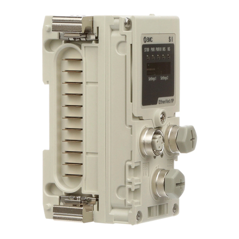
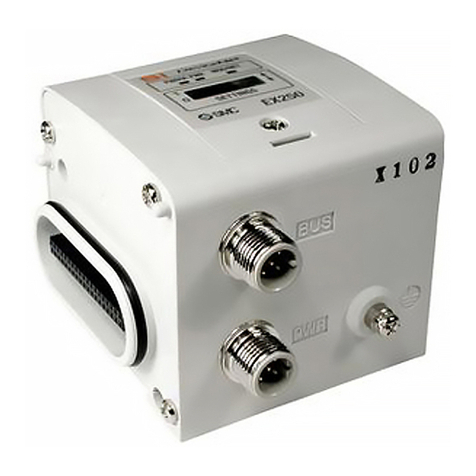
Thank you for purchasing an SMC EX250 Series Fieldbus device (Hereinafter
referred to as "SI unit" ).
Please read this manual carefully before operating the product and make sure you
understand its capabilities and limitations.
Please keep this manual handy for future reference.
To obtain more detailed information about operating this product,
please refer to the SMC website (URL http://www.smcworld.com) or
contact SMC directly.
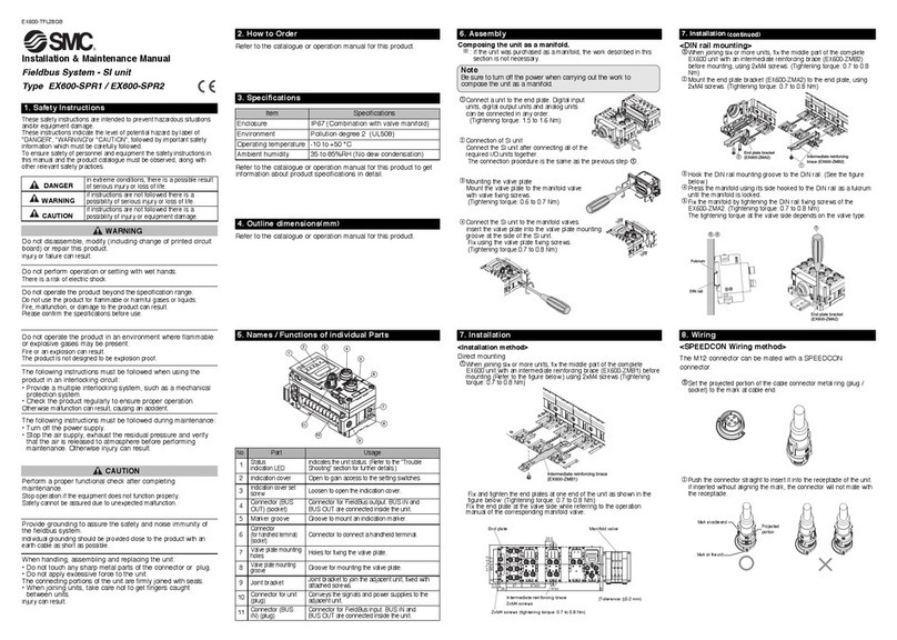
Safety I structio s
These safety instructions are intended to prevent hazardous situations and/or
equipment damage.
These instructions indicate the level of potential hazard with the labels of
"Caution", " Warning" or "Danger". They are all important notes for safety and
must be followed in addition to International standards (ISO/IEC) and other safety
regulations.
War i g
Cautio
After mai te a ce is complete, perform appropriate fu ctio al i spectio s.
Stop operation if the equipment does not function properly.
Safety cannot be assured in the case of unexpected malfunction.
CAUTIO indicates a hazard with a low level of risk which, if
not avoided, could result in minor or moderate injury.
Cautio :
War i g:
Da ger:
WAR I G indicates a hazard with a medium level of risk
which, if not avoided, could result in death or serious injury.
DA GER indicates a hazard with a high level of risk which, if
not avoided, will result in death or serious injury.
Operator
This operation manual is intended for those who have knowledge of machinery
using pneumatic equipment, and have sufficient knowledge of assembly,
operation and maintenace of such equipment. Only those persons are allowed
to perform assembly, operation and maintenance.
Read and understand this operation manual carefully before assembling,
operating or providing maintenance to the product.
Wiri g
Commu icatio wiri g
M12 5-pin plug A-code
DRAI
Signal name Configuration
V+
V-
CA _L
1
Pin o.
2
3
5
CA _H4
SV24 V
Description Function
+24 V for solenoid valve.
SV0 V 0 V for solenoid valve
SW24 V +24 V for input block
FE Ground
1
o.
2
3
5
SW0 V 0 V for input block4
Power supply wiri g
Refer to "Safety Instructions" on this manual when selecting the power supply.
M12 5-pin B-code (reverse)
SW power is supplied to the sensor connected to the input block. There is a voltage drop up
to maximum 1 V inside the SI unit when SW power is supplied. Select a sensor taking this
voltage drop into consideration. If 24 V must be supplied to the sensor, it is necessary to
increase the SW power supply voltage so that the input voltage of the sensor will be 24 V with
the actual load. (Allowable SW power supply range: 19.2 V to 28.8 V)
FE co ectio
Connect the ground terminal to the ground. Resistance to the ground should be 100 Ω
or less.
PWR Green LED is O when power for Device etTM communication is supplied.
Green LED is O
Red LED is flashing
Red LED is O MAC ID duplication error or BUS OFF error (serious communication error)
I/O connection time-out (minor communication error)
Note
1. The power supply should be off while setting the switches.
2. Be sure to set the switches before use.
3. After setting the switches, close the switch cover and tighten the screw to the
specified torque. (Tightening torque: 0.6 m)
∗: Output o. starts from 0, and will be assigned to the valves in order from the SI unit mounted side
∗: Manifold wiring is double wired as standard ("double wiring specification"), and the output
numbers are assigned in order from A side to B side. If the mounted valves are single solenoid
valves, the output on B side will be empty. (See Figure a)
∗: Special wiring specification with a mixed wiring of single solenoid and double solenoid can be
specified with a wiring specification sheet. This makes it possible to specify the output numbers
without empty outputs. (See Figure b)
∗: Each bit status, 0 or 1, of the data shows the O or OFF solenoid valve status (0: OFF, 1: O ),
and the output number starting from 0 will be assigned to from the lowest bit of the memory data.
∗: EX250-SD 1 disconnects the I/O connection when the solenoid valve power supply decreases or
when the input block fuse is detected to be broken (EX250-SD 1-X102 does not disconnect the I/O
connection).
Address setting
I put No. assig me t
The inputs of the Input block are assigned from the SI unit side Input block in the order
0,1,2…maximum of 31.
