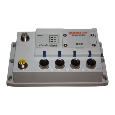
manuals.online logo
Brands
  1. Home
  2. •
  3. Brands
  4. •
  5. SMC Networks
  6. •
  7. Recording Equipment
  8. •
  9. SMC Networks EX120-SCM1 User manual

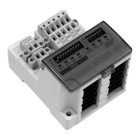
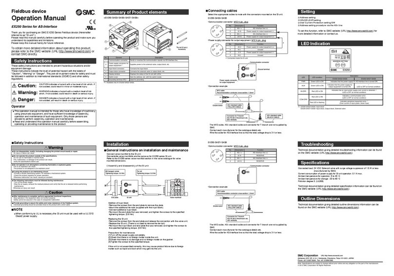
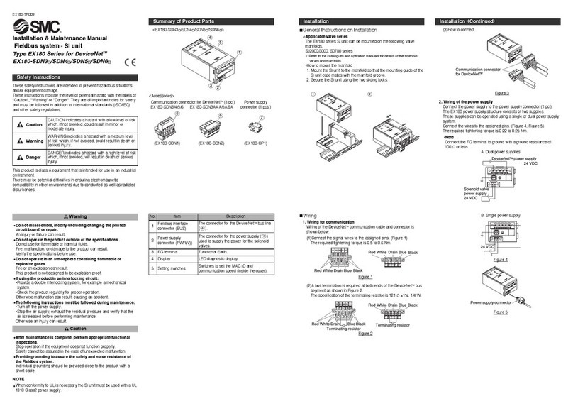
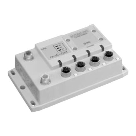
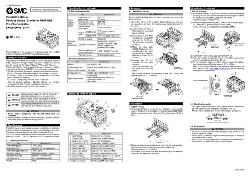
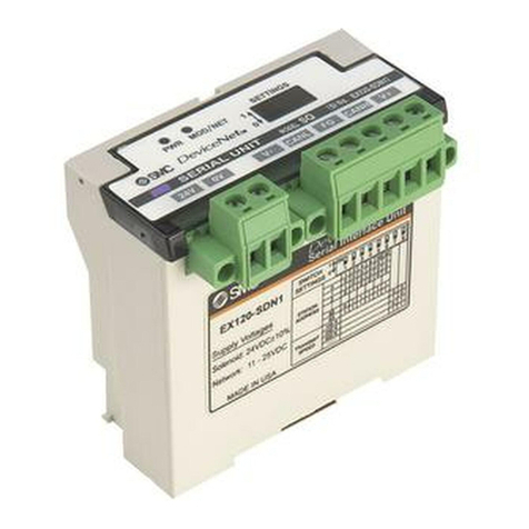
SMC Networks EX120-SCM1 User manual

DDDDDD
Note 1) DN1’s occupied points are 16 inputs and 16 outputs, while
DN1-X26 has 0 inputs and 16 outputs.
Note 2) Please consult SMC for networks other than those above.
Communication protocol
DN1
DN1-X26
MJ1
CS1
CS2
SL1
SL2
UW1
UH1
CM1
CM3
DeviceNet Note 1)
DeviceNet Note 1)
CC-Link
OMRON Corp.: CompoBus/S (16 outputs)
OMRON Corp.: CompoBus/S (8 outputs)
Panasonic Industrial Devices SUNX Co., Ltd.: S-LINK (16 outputs)
Panasonic Industrial Devices SUNX Co., Ltd.: S-LINK (8 outputs)
NKE Corp.: Fieldbus System
NKE Corp.: Fieldbus H System
CompoNet™ NPN (Positive common)
CompoNet™ PNP (Negative common)
CE-compliant





—
—
—
—


SV1000/2000/3000/4000
VQ1000/2000
SY3000/5000/7000
SY3000/5000 SY3000/5000
Small unit compatible with maximum 16 outputs
Compatible with a variety of communication networks
EX120 Series EX121 Series EX122 Series
How to Order SI Unit
0
1
2
Plug-in
Flat ribbon cable DIN rail mounting
Plug-in DIN rail mounting
DN1
EX12 S0
Valve interface
EX120/121/122 Series
For Output
777
EX12
EX140
EX180
EX260
EX250
EX600
EX500
EX510
PCA
EX
EX12
Note 1) Please note that the version is subject to change.
Note 2) Each file can be downloaded from SMC’s website (http://www.smcworld.com).
Note 3) For detailed specifications other than the above, refer to the operation manual that can be downloaded from SMC website. (http://www.smcworld.com).
Note 4) Since this is a special product, a manifold part number is not specified. Please consult SMC for the manifold integrated type.
Model
EX12-SDN1
DeviceNet™
Release 2.0
125 k/250 k/500 kbps
100 mA or less
Sink/NPN (Positive common)
IP20
35 to 85%RH (With no condensation)
1500 VAC for 1 min. between whole external terminal and enclosure
2 MΩor more (500 VDC) between whole external terminal and enclosure
EX120: 110 g or less, EX121: 140 g or less, EX122: 130 g or less
24 VDC+10%/–5%
EDS file
16/16
CE marking
Communication connector 1 pc.,
Power supply connector 1 pc.
0/16
Note 4)
EX12-SDN1-X26
EX12-SMJ1
CC-Link
EX12-SCS1
EX12-SCS2 EX12-SSL1
EX12-SSL2 EX12-SUW1 EX12-SUH1
Ver. 1.10 — — — —
156 k/625 kbps
2.5 M/5 M/10 Mbps
750 kbps 28.5 kbps 28.5 kbps 29.4 kbps
32/32 (1 station,
remote I/O stations)
Not provided
—
—
Communication speed
Configuration file Note 2)
Terminating resistor
For unit
For valve
Output type
Number of outputs
Load
Enclosure
Operating humidity range
Withstand voltage
Insulation resistance
Applicable
system
Protocol
Version Note 1)
Internal current consumption (Unit)
Standards
Weight
Accessory
0 to +55°C (Valve 8 points ON)
0 to +50°C (Valve 16 points ON)
CompoNet™ Communication Specifications
SI Unit Specifications
Protocol
Communication speed
Configuration file
I/O occupation area (Inputs/Outputs)
Terminating resistor
CompoNet™
93.75 kbps/1.5 M/3 M/4 Mbps
EDS file (Download from SMC’s website)
0/16
Not provided
Note) For details about the communication speed or each setting instruction, check the operation manual that can be downloaded from SMC website.
Note) Communication connector (for the opposite side) is not provided.
Model
Power supply voltage
Internal current consumption (Unit)
Output
Environment
Standards
Weight
Accessory
For unit
For valve
Output type
(Valve common polarity)
Number of outputs
Load
Fail safe
Enclosure
Operating
temperature range
Operating humidity range
Withstand voltage
Insulation resistance
14 to 26.4 VDC
24 VDC+10%/
–
5%
100 mA or less
35 to 85%RH (With no condensation)
1500 VAC for 1 min. between whole external terminal and enclosure
2 MΩor more (500 VDC) between whole external terminal and enclosure
CE marking
EX120: 100 g or less, EX121: 120 g or less, EX122: 110 g or less (including accessory)
Power supply connector (EX9-CP2) 1 pc.Note)
16 points
Solenoid valve with/surge voltage suppressor 24 VDC, 2.1 W or less (SMC)
Hold/Clear (Setting via network)
IP20
0 to +55°C (Valve 8 points ON)
0 to +50°C (Valve 16 points ON)
Sink/NPN output (Positive common) Source/PNP (Negative common)
EX120-SCM1 EX121-SCM1 EX122-SCM1 EX120-SCM3 EX121-SCM3 EX122-SCM3
SI Unit Specifications
OMRON Corp.:
CompoBus/S
NKE Corp.:
Fieldbus System
NKE Corp.:
Fieldbus H System
—
SCS1: 0/16
SCS2: 0/8
SSL1: 0/16
SSL2: 0/8 0/16 0/16
11 to 25 VDC 15 to 30 VDC
14 to 26.4 VDC
24 VDC+10%/–5%
(Common power supply)
24 VDC±10%
(Common power supply)
16 points SCS1/SSL1: 16 points
SCS2/SSL2: 8 points 16 points
Solenoid valve with surge voltage suppressor 24 VDC, 2.1 W or less (SMC)
Hold/Clear
(Switch setting) ClearClear Hold/Clear
(Switch setting) Clear
Communication
Power supply
voltage
OutputEnvironment
I/O occupation area
(Inputs/Outputs)
Fail safe
Operating temperature
range
EX120/121/122 Series
Panasonic Industrial
Devices SUNX Co., Ltd.:
S-Link
778
9.5
60.8
28.8
64
29.5
60.8
28.864
60.8
64 1.2 28.8
10.2
5.460.8
28.864
5.4
10.2 228.8
60.8
64
10.2
5.460.8
28.864
MIL connector
(20 pins, socket)
OUT
5.460.8
64 10.2 28.8
OUT
5.460.8
64 10.2 28.8 2
OUT
28.8
64
60.8
Communication connector
Valve power supply
Terminal block cover
Position indicator LED
10.2
5.4
Terminal block cover
Position indicator LED
Communication
connector
Valve power
supply
Terminal block cover
Position indicator LED
Communication connector
Valve power supply
Position indicator LED
Terminal block cover
Screw terminal block
Position indicator LED
Terminal block cover
Power supply connector
Communication connector
Position
indicator LED
Terminal block cover
Screw terminal
block
DIN rail mounting bracket
MIL connector
(20 pins, socket)
Position
indicator LED
Terminal block cover
Screw terminal
block
DIN rail mounting bracket
MIL connector
(20 pins, socket)
Position indicator LED
Terminal block cover
Power supply
connector
Communication
connector
MIL connector
(20 pins, socket)
DIN rail mounting bracket
Terminal block cover
Position indicator LED
Screw terminal block
DIN rail mounting bracket
Terminal block cover
Position indicator LED
Power supply connector
Communication connector
DIN rail mounting bracket
Tightening torque
0.6N·m
Tightening torque
0.6N·m
DIN rail mounting bracket
EX120
EX120-SMJ1, SCS,
SSL, SUW1, SUH1
EX120-SDN1(-X26) EX120-SCM
EX121
EX121-SMJ1, SCS,
SSL, SUW1, SUH1
EX121-SDN1(-X26) EX121-SCM
EX122
EX122-SMJ1, SCS,
SSL, SUW1, SUH1
EX122-SDN1(-X26) EX122-SCM
SI Unit Dimensions/Parts Description
For Output EX120/121/122 Series
779
EX12
EX140
EX180
EX260
EX250
EX600
EX500
EX510
PCA
EX
EX12
How to Order Options (For EX12-SCM)
Cable identification label
(Flat cable: Black, blue, white, red)
Black
Lock lever
Black
Lock lever
Cable identification label
(Flat cable: Black, blue, white, red)
Power supply connector: T-branch type power supply connector.
EX9-CP3
Power supply connector: Straight type power supply connector. This connector is supplied at shipment.
EX9-CP2
Communication connector: Terminal block connector for round cable (VCTF).
Use this connector for the VCTF cable.
The communication connector does not come with this product.
EX9-CCM2
Communication connector: Press-in connector for flat cable.
Use this connector for the standard dedicated flat cable.
The communication connector does not come with this product.
EX9-CCM1
EX120/121/122 Series
780
3
Common power supply of unit and valve
Enclosure IP65
Compatible with the VQ valves
Mounting specifications
SL1
SL2
UW1
UH1
Panasonic Industrial Devices SUNX Co., Ltd.: S-LINK (16 outputs)
Panasonic Industrial Devices SUNX Co., Ltd.: S-LINK (8 outputs)
NKE Corp.: Fieldbus System
NKE Corp.: Fieldbus H System
—
—
—
—
CE-compliant





CE-compliant
DN1
DN1-X26
MJ1
CS1
CS2
DeviceNet Note)
DeviceNet Note)
CC-Link
OMRON Corp.: CompoBus/S (16 outputs)
OMRON Corp.: CompoBus/S (8 outputs)
MJ1 CC-Link 
CE-compliant
EX123 Series
VQ2000/4000/5000
EX124 Series
VQ2000/4000/5000
EX126 Series
SV1000/2000/3000
SY3000/5000/7000
VQC1000/2000/4000/5000
Note) DN1’s occupied points are 16 inputs and 16 outputs,
while DN1-X26 has 0 inputs and 16 outputs.
Enclosure IP65 (EX123, EX124), IP67 (EX126)
Maximum 16 outputs
How to Order SI Unit
Unit specifications
SL1EX12 SU3
Communication protocol
U
D
Mount a unit to the U side of the manifold
Mount a unit to the D side of the manifold
Unit specifications
4
Separate power supply of unit and valve
Enclosure IP65
Compatible with the VQ valves
U
D
Mount a unit to the U side of the manifold
Mount a unit to the D side of the manifold
DN1EX12 SU4
Mounting specifications
Communication protocol
Unit specifications
6
Separate power supply of unit and valve
Enclosure IP67
Compatible with the SY/SV/VQC valves
DMount a unit to the D side of the manifold
MJ1EX12 SD6
Mounting specifications
Communication protocol
EX123/124/126 Series
For Output
781
EX12
EX140
EX180
EX260
EX250
EX600
EX500
EX510
PCA
EX
EX12
SI Unit Specifications
The electrical specification is the same for EX12. Refer to page 2052.
The weight of the EX123, 124, or 126 is 240g or less.
4 unit mounting screws (M4 x 10) are included when shipped.
How to Order Options
Fuse for replacement
A fuse for replacement used for EX126D-SMJ1.
EX9 FU20
Applicable model
Rated current
EX126D-SMJ1
2.0 A
Dripproof plug assembly
Use for the unused wiring entry (G1/2).
Incorrect handling of the wiring entry may allow foreign matter to enter the SI unit, which will lead to a malfunction and damage to the SI unit.
AXT100 B04A
Fuse
EX123/124/126 Series
782
16.8
Housing cover
19.8
65.7
68.2
6.6
30.4
42
(72.5)
5.5 67
114
35.3
19.8
4 x G1/2
Wiring entry
(72.5)
5.5
56.4
19
11.653.8
19
19.8
67
114
Housing cover
Position indicator LED
Screw terminal block
Housing cover diagram
EX123: 2 x G1/2
EX124: 4 x G1/2
Wiring entry
Housing cover diagram
Position indicator LED Screw terminal block
Housing bottom diagram
Power supply fuse
for solenoid valve
Power supply fuse
for communication
Note) The housing cover of the EX124U/D-SMJ1 is the same as
that of the EX126D-SMJ1.
EX126D-SMJ1
SI Unit Dimensions/Parts Description
EX123-S, EX124-S
For Output EX123/124/126 Series
783
EX12
EX140
EX180
EX260
EX250
EX600
EX500
EX510
PCA
EX
EX12
DN1EX140 S
Communication protocol
DN1
MJ1
CS1
CS2
SL1
SL2
UW1
UH1
DeviceNet™
CC-Link
OMRON Corp.: CompoBus/S (16 outputs)
OMRON Corp.: CompoBus/S (8 outputs)
Panasonic Industrial Devices SUNX Co., Ltd.: S-LINK (16 outputs)
Panasonic Industrial Devices SUNX Co., Ltd.: S-LINK (8 outputs)
NKE Corp.: Fieldbus System
NKE Corp.: Fieldbus H System




—
—
—
—
CE-compliant
Note) Please consult SMC for networks other than those above.
SZ3000 SQ1000/2000
Thinner unit with low height
Maximum 16 outputs
How to Order SI Unit
EX140 Series
For Output
784
33.4
(36)
(11.5)
34.4
94.5
34.494.5
33.4
Position indicator LEDPosition indicator LED
Power supply connector
Communication connector
Screw terminal block
Standards
Weight
Accessory
EX140-SDN1 EX140-SMJ1 EX140-SCS1
EX140-SCS2
EX140-SSL1
EX140-SSL2 EX140-SUW1 EX140-SUH1
SI Unit Specifications
Model
Communication speed
Configuration file Note 2)
Terminating resistor
For unit
For valve
Output type
Number of outputs
Load
Enclosure
Operating humidity range
Withstand voltage
Insulation resistance
Applicable
system
Protocol
Version Note 1)
Internal current consumption (Unit)
Fail safe
Operating temperature
range
I/O occupation area
(Inputs/Outputs)
Communication
OutputEnvironment
Power supply
voltage
DeviceNet™
Release 2.0
125 k/250 k/500 kbps
11 to 25 VDC
16 outputs
Solenoid valve with surge voltage suppressor 24 VDC, 2.1 W or less (SMC)
24 VDC+10%/–5%
EDS file
0/16
Hold/Clear
(Switch setting)
CE marking
Communication connector 1 pc.,
Power supply connector 1 pc.
32/32
(1 station, remote
I/O stations)
CC-Link OMRON Corp.:
CompoBus/S
Panasonic Industrial
Devices SUNX Co., Ltd.:
S-Link
NKE Corp.:
Fieldbus System
NKE Corp.:
Fieldbus H System
Ver. 1.10 — — — —
156 k/625 kbps
2.5 M/5 M/10 Mbps
750 kbps 28.5 kbps
—
28.5 kbps 29.4 kbps
SCS1: 0/16
SCS2: 0/8
SSL1: 0/16
SSL2: 0/8
Not provided
0/16
15 to 30 VDC
14 to 26.4 VDC
24 VDC+10%/–5%
(Common
power supply)
100 mA or less
Sink/NPN (Positive common)
IP20
35 to 85%RH (With no condensation)
1500 VAC for 1 min. between whole external terminal and enclosure
2 MΩor more (500 VDC) between whole external terminal and enclosure
80 g or less
SCS1/SSL1: 16 outputs
SCS2/SSL2: 8 outputs
0 to +55°C (Valve 8 points ON)
0 to +50°C (Valve 16 points ON)
16 outputs
—
—
Clear
24 VDC±10%
(Common power supply)
Note 1) Please note that the version is subject to change.
Note 2) Each file can be downloaded from SMC website (http://www.smcworld.com).
Note 3) For detailed specifications other than the above, refer to the operation manual that can be downloaded from SMC website (http://www.smcworld.com).
SI Unit Dimensions/Parts Description
EX140-SMJ1, SCS, SSL, SUW1, SUH1 EX140-SDN1
For Output EX140 Series
785
EX12
EX140
EX180
EX260
EX250
EX600
EX500
EX510
PCA
EX
EX140
®
RoHS
Communication protocol
DN3
DN4
DN5
DN6
MJ3
MJ5
DeviceNet™ (32 points Sink/NPN (Positive common))
DeviceNet™ (16 points Sink/NPN (Positive common))
DeviceNet™ (32 points Source/PNP (Negative common))
DeviceNet™ (16 points Source/PNP (Negative common))
CC-Link (32 points Sink/NPN (Positive common))
CC-Link (32 points Source/PNP (Negative common))
Note) Please consult SMC for networks other than those above.
SJ2000/3000 S0700
EX180-C1 EX180-C2
Note) S0700 is not yet UL-compatible.
Thinner unit with low height
Maximum 32 outputs
How to Order SI Unit
DN3
EX180 S
Communication connector type
Nil
A
T-branch type
Straight type
Note) Communication and
power supply connectors
are included.
How to Order Options
Communication connector
Connector for the network cable, included when shipped.
EX180 C DN 1
DN
MJ
Communication
protocol
For EX180-SDN
For EX180-SMJ
1
2
Communication connector type
T-branch type
Straight type
Power supply connector
Connector for power supply, included when shipped.
EX180 CP1
EX180 Series
For Output
786
EX180-SDN5
EX180-SDN6 EX180-SMJ5
EX180-SDN3
EX180-SDN4 EX180-SMJ3
SI Unit Specifications
Model
CommunicationOutputEnvironment
Communication speed
Configuration file Note 2)
Terminating resistor
For unit
For valve
Output type
Number of outputs
Load
Enclosure
Operating temperature range
Operating humidity range
Withstand voltage
Insulation resistance
Applicable
system
Protocol
Version Note 1)
Power supply
voltage
Internal current consumption (Unit)
I/O occupation area
(Inputs/Outputs)
Fail safe
Standards
Weight
Accessory
DeviceNet™
Release 2.0
125 k/250 k/500 kbps
Not provided
11 to 25 VDC
0.1 A or less
EDS file
Communication connector 1 pc.,
Power supply connector 1 pc.
Communication connector 1 pc.,
Power supply connector 2 pcs.
Ver. 1.10
CC-Link
32/32 (1 station)
32 outputs
21.6 to 26.4 VDC
SDN3: 32 outputs
SDN4: 16 outputs
SDN5: 32 outputs
SDN6: 16 outputs
SJ2000/3000, S0700 series
manifold valves
SJ2000/3000, S0700 series
manifold valves
IP20
–10 to 50°C
35 to 85%RH (With no condensation)
500 VAC for 1 min. between whole external terminal and FG
10 MΩor more (500 VDC) between whole external terminal and FG
CE marking, UL (CSA)
110 g or less (including accessory)
Source/PNP (Negative common)
Sink/NPN (Positive common)
Source/PNP (Negative common)
Sink/NPN (Positive common)
24 VDC±10%/–5%
156 k/625 kbps
2.5 M/5 M/10 Mbps
Built into the unit (Switch setting, 110 Ω)
Hold/Clear
(Switch setting)
Note 1) Please note that the version is subject to change
Note 2) Each file can be downloaded from SMC website (http://www.smcworld.com).
Note 3) For detailed specifications other than the above, refer to the operation manual that can be downloaded from SMC website
(http://www.smcworld.com).
Note 4) The EX180-SDN1/2cannot be mounted on the manifold for the EX180-SDN3/4/5/6. Additionally, the EX180-SDN3/4/5/6cannot be
mounted on the manifold for the EX180-SDN1/2.
Note 5) The EX180-SMJ1cannot be mounted on the manifold for the EX180-SMJ3/5. Additionally, the EX180-SMJ3/5cannot be mounted on the manifold
for the EX180-SMJ1.
SDN3: 0/32
SDN4: 0/16
SDN5: 0/32
SDN6: 0/16
For Output EX180 Series
CSP + file
787
EX12
EX140
EX180
EX260
EX250
EX600
EX500
EX510
PCA
EX
EX180
A
93.3
80
77
42.3
93.3
80
77
42.3
EX180-SMJ3, SMJ5
EX180-SDN3, SDN4, SDN5, SDN6
SI Unit Dimensions/Parts Description
(39.7)
30.9
Power supply connector
(For solenoid valve)
Power supply connector
(Control unit power supply
for SI unit)
Communication
connector
M3
Ground terminal
Before mounting connector (accessory)
Power supply connector
(For solenoid valve)
Communication
connector
Before mounting connector (accessory)
M3
Ground terminal
(39.7)
30.9
EX180 Series
788

This manual suits for next models

5

Other SMC Networks Recording Equipment manuals

SMC Networks EX250 Series User manual

SMC Networks

SMC Networks EX250 Series User manual

SMC Networks EX500-GDN1 Instruction Manual

SMC Networks

SMC Networks EX500-GDN1 Instruction Manual

SMC Networks EX250-SDN1-X102 Instruction Manual

SMC Networks

SMC Networks EX250-SDN1-X102 Instruction Manual

SMC Networks EX260 Series User manual

SMC Networks

SMC Networks EX260 Series User manual

SMC Networks EX510-GPR1 Series User manual

SMC Networks

SMC Networks EX510-GPR1 Series User manual

SMC Networks EX250 Series User manual

SMC Networks

SMC Networks EX250 Series User manual

SMC Networks EX600-SEC Series User manual

SMC Networks

SMC Networks EX600-SEC Series User manual

SMC Networks EX260 Series User manual

SMC Networks

SMC Networks EX260 Series User manual

SMC Networks EX250-SDN1 User manual

SMC Networks

SMC Networks EX250-SDN1 User manual

SMC Networks EX180-SMJ3 Series User manual

SMC Networks

SMC Networks EX180-SMJ3 Series User manual

SMC Networks EX12-SCM Series User manual

SMC Networks

SMC Networks EX12-SCM Series User manual

SMC Networks EX250 Series Installation manual

SMC Networks

SMC Networks EX250 Series Installation manual

SMC Networks EX250 Series User manual

SMC Networks

SMC Networks EX250 Series User manual

SMC Networks EX9-OET1 User manual

SMC Networks

SMC Networks EX9-OET1 User manual

SMC Networks EX600-SPR1 Instruction Manual

SMC Networks

SMC Networks EX600-SPR1 Instruction Manual

SMC Networks EX600-SEN1 Instruction Manual

SMC Networks

SMC Networks EX600-SEN1 Instruction Manual

SMC Networks EX260 Series User manual

SMC Networks

SMC Networks EX260 Series User manual

SMC Networks EX500 Series User manual

SMC Networks

SMC Networks EX500 Series User manual

SMC Networks EX600-SDN2 User manual

SMC Networks

SMC Networks EX600-SDN2 User manual

SMC Networks EX250 Series User manual

SMC Networks

SMC Networks EX250 Series User manual

SMC Networks EX260 Series User manual

SMC Networks

SMC Networks EX260 Series User manual

SMC Networks EX180-SDN4 Series Instruction Manual

SMC Networks

SMC Networks EX180-SDN4 Series Instruction Manual

SMC Networks EX120-SDN1-X2 User manual

SMC Networks

SMC Networks EX120-SDN1-X2 User manual

SMC Networks EX600-SPN3 User manual

SMC Networks

SMC Networks EX600-SPN3 User manual

Popular Recording Equipment manuals by other brands

ADS Technologies USBAV-170 user guide

ADS Technologies

ADS Technologies USBAV-170 user guide

MicroRidge GageWay III user guide

MicroRidge

MicroRidge GageWay III user guide

JK Audio Daptor Two user guide

JK Audio

JK Audio Daptor Two user guide

Coomber Classmaster Pro operating instructions

Coomber

Coomber Classmaster Pro operating instructions

Native Instruments TRAKTOR KONTROL X1 Setup guide

Native Instruments

Native Instruments TRAKTOR KONTROL X1 Setup guide

Outlaw 976 Faq

Outlaw

Outlaw 976 Faq

ANTUMBRA MULT Building instructions

ANTUMBRA

ANTUMBRA MULT Building instructions

TINRS Tuesday manual

TINRS

TINRS Tuesday manual

ETS SMI16 instructions

ETS

ETS SMI16 instructions

PS Engineering PAC45T System installation and operation manual

PS Engineering

PS Engineering PAC45T System installation and operation manual

PIRATE MIDI BRIDGE6 instruction manual

PIRATE MIDI

PIRATE MIDI BRIDGE6 instruction manual

RYK Modular M185 user manual

RYK Modular

RYK Modular M185 user manual

Beckhoff CX B110 Series manual

Beckhoff

Beckhoff CX B110 Series manual

BBE 202 Series Information manual

BBE

BBE 202 Series Information manual

Rheem Raypak Raymote Installation and operation manual

Rheem

Rheem Raypak Raymote Installation and operation manual

Emerson QuickPanel+ IC755C S06RD Series quick start guide

Emerson

Emerson QuickPanel+ IC755C S06RD Series quick start guide

Tascam Frontier HD-P2 Reference card

Tascam

Tascam Frontier HD-P2 Reference card

Radionics D9210B Program entry guide

Radionics

Radionics D9210B Program entry guide

manuals.online logo
manuals.online logoBrands
  • About & Mission
  • Contact us
  • Privacy Policy
  • Terms and Conditions

Copyright 2025 Manuals.Online. All Rights Reserved.