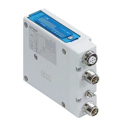
NOTE
1. Be sure to turn off the power supply before setting the switches.
2. Be sure to set these switches before use.
3. After setting the switch, close the switch protective cover and tighten the screws with
proper tightening torque. (Tightening torque: 0.6 Nm)
•Remote control (SW1 Dip switches 1-4 OFF)
SMC's EX250 SI Unit will respond to the following Rockwell Automation BOOTP/DHCP
Server commands.
Enable DHCP
Selecting this function will enable the EX250 SI Unit to retrieve its IP address∗from the
BOOTP/DHCP Server. If DHCP is enabled the EX250 SI Unit will retrieve its IP address∗
during the next power up.
If the IP address∗is not acquired after approximately 30 seconds from when the power is
supplied, the previous IP address∗from immediately before will be set.
Disable BOOTP/DHCP
Selecting this function will disable the EX250 from retrieving its IP address∗from the
BOOTP/DHCP Server, and will cause the EX250 to retain its current configuration during
the next power up.
•DHCP mode (SW1 Dip switches 1-4 ON)
The IP address∗is acquired from the DHCP Server. If the IP address∗is not acquired after
approximately 30 seconds from when the power is supplied, the previous IP address∗from
immediately before will be set. The IP address∗will be lost if the power supply is
disconnected.
•Manual set up of IP address∗
The IP address∗range is 192.168.0.1 to 192.168.0.14.
∗: Information such as the subnet masks is included.
Default settin s
At the time of factory shipment, the product is in "Remote Control Mode" and set to "Enable
DHCP".
NOTE
If the stored address of an EX250 is not known, please go to the "DHCP Mode" section.
Display Description
Insufficient power supply for input and control
Insufficient power supply for solenoids
Normal power supply for solenoids
Normal power supply for input and control
Setting error (Device has not been configured)
The power supply for control is OFF
Operating normally
Recoverable internal error
Unrecoverable internal error
The power supply for control is OFF or IP address not set
Multiple EtherNet/IPTM-level communications time out
EtherNet/IPTM-level communication not established
Multiple EtherNet/IPTM-level communications established
IP address duplicated
OFF
OFF
Green light ON
Green light ON
Green flashes
OFF
Green light ON
Red flashes
Red light ON
OFF
Red flashes
Green flashes
Green light ON
Red light ON
SOL
PWR
MS
NS
Refer to the operation manual from SMC website (URL http://www.smcworld.com) for more
information about maintenance.
Specifications
Refer to the operation manual from SMC website (URL http://www.smcworld.com) for more
information about dimensions.
Power for SI Unit/Input Block: 24 VDC ±20%, 1.1 A or less
Inside of SI Unit: 0.1 A or less
Input block: 1 A or less (Depending on number of connecting
sensors and specifications)
Power for solenoid valve: 24 VDC +10%/-5%, 2 A or less
(Depending on number of solenoid valve station and
specifications)
Connection load: Solenoid valve with protection circuit for 24 VDC and 1.5 W or less surge
voltage. (made by SMC)
Operating ambient temp: 5 to 45 oC Storage ambient temp: -20 to +60 oC
Pollution degree: Pollution degree 3 (UL508)
Technical documentation giving detailed specification information can be found on the SMC
website (URL http://www.smcworld.com).
)(
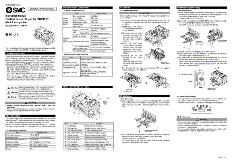
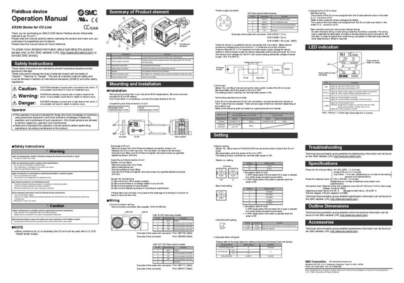
Fieldbus device
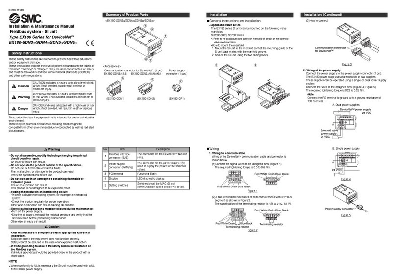
Operation Manual
EX250 Series for EtherNet/IPTM
Safety Instructions
Safety Instructions
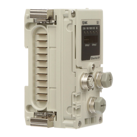
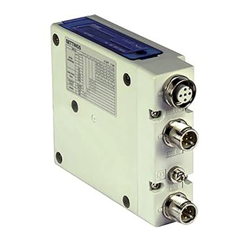
Summary of Product parts
Mountin and Installation
CAUTION indicates a hazard with a low level of risk which, if
not avoided, could result in minor or moderate injury.
Caution:
Warnin :
Dan er:
WARNING indicates a hazard with a medium level of risk
which, if not avoided, could result in death or serious injury.
DANGER indicates a hazard with a high level of risk which, if
not avoided, will result in death or serious injury.
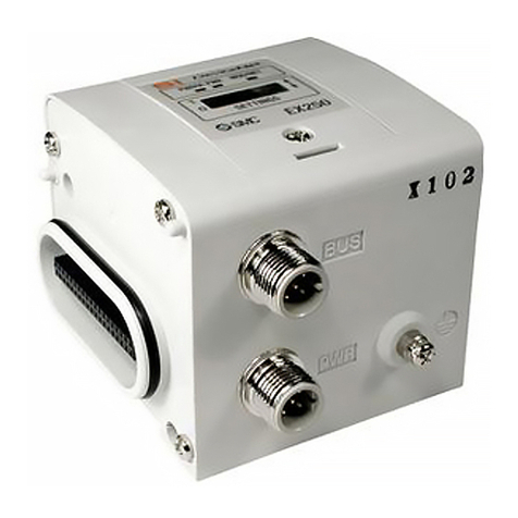
Thank you for purchasing an SMC EX250 series Fieldbus device (Hereinafter
referred to as "SI Unit" ).
Please read this manual carefully before operating the product and make sure you
understand its capabilities and limitations. Please keep this manual handy for
future reference.
These safety instructions are intended to prevent hazardous situations and/or
equipment damage.
These instructions indicate the level of potential hazard with the labels of
"Caution", "Warning" or "Danger". They are all important notes for safety and must
be followed in addition to International standards (ISO/IEC) and other safety
regulations.
Do not operate the product outside of the specifications.
Do not use for flammable or harmful fluids.
Fire, malfunction, or damage to the product can result.
Verify the specifications before use.
Do not disassemble, modify (includin chan in the printed circuit board) or repair.
An injury or failure can result.
Do not operate in an atmosphere containin flammable or explosive ases.
Fire or an explosion can result.
This product is not designed to be explosion proof.
If usin the product in an interlockin circuit:
•Provide a double interlocking system, for example a mechanical system.
•Check the product regularly for proper operation.
Otherwise malfunction can result, causing an accident.
The followin instructions must be followed durin maintenance:
•Turn off the power supply.
•Stop the air supply, exhaust the residual pressure and verify that the air is released before performing
maintenance.
Otherwise an injury can result.
After maintenance is complete, perform appropriate functional inspections.
Stop operation if the equipment does not function properly.
Safety cannot be assured in the case of unexpected malfunction.
When handlin the unit or assemblin /replacin units:
•Do not touch the sharp metal parts of the connector or plug for connecting units.
•Take care not to hit your hand when disassembling the unit.
The connecting portions of the unit are firmly joined with seals.
•When joining units, take care not to get fingers caught between units.
An injury can result.
Warnin
Caution
Operator
The operation manual is intended for those who have knowledge of machinery
using pneumatic equipment, and have sufficient knowledge of assembly,
operation and maintenance of such equipment. Only those persons are
allowed to perform assembly, operation and maintenance.
Read and understand the operation manual carefully before assembling,
operating or providing maintenance to the product.
NOTE
•The direct current power supply to combine should be UL1310 Class2 power supply
when conformity to UL is necessary.
To obtain the operation manual about this product, please
refer to the SMC website (URL http://www.smcworld.com) or
contact SMC directly.
Refer to the operation manual EX250-IE1 / -IE2 / -IE3 for the
input block specifications,
and EX9-OET1 / -OET2 / -OEP1 / -OEP2 / PE1 for the output
block and power block specifications.
Provide roundin to assure the safety and noise resistance of the Fieldbus system.
Individual grounding should be provided close to the product with a short cable.
