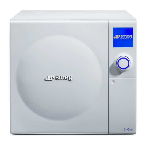
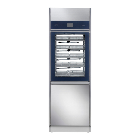
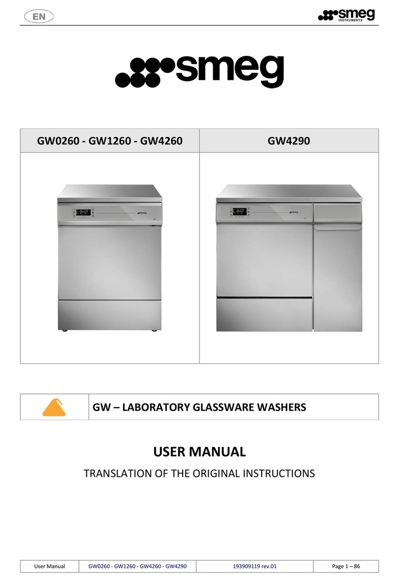
Smeg WD6010 User manual

WD6010
WD7010
WD7015
WD6010 –WD7010 –WD7015
WD –WASHER DISINFECTOR –Hospital sector
- USER MANUAL -
Translation of the original instructions issued in Italian

USER MANUAL
WD6010 –WD7010 –WD7015
Page 2 - 168
Summary
1 INITIAL RECCOMENDATIONS..................................................................................................................... 7
2 SERVICE LIFE .............................................................................................................................................. 8
3 INTENDED USE AND CLASSIFICATION........................................................................................................ 8
3.1 INTENDED USE................................................................................................................................... 8
3.2 WD CLASSIFICATION.......................................................................................................................... 9
3.3 STANDARD 15883............................................................................................................................ 10
3.4 DEFINITION: “RESPONSIBLE BODY” OF THE DEVICE........................................................................ 11
3.5 TYPE OPERATOR AND “SUPERUSER”............................................................................................... 11
4 PRESENTATION........................................................................................................................................ 12
4.1 WD6010 and GW6010 - MACHINE WITH SWINGING DOOR........................................................... 13
4.2 WD7010 - GW7010, WD7015 –GW7015 –MACHINE WITH SLIDING DOORS................................ 16
4.2.1 OPTIONAL BARCODE SCANNER –WD-CODESCAN.................................................................. 20
5 CONFIGURATIONS AND OPTIONALS........................................................................................................ 22
5.1 WD6010........................................................................................................................................... 23
5.1.1 Models without steam heating ............................................................................................... 23
5.1.2 Models equipped with Steam heating system ........................................................................ 24
5.2 WD7010........................................................................................................................................... 25
5.2.1 50Hz models ............................................................................................................................ 25
5.2.2 60Hz Models............................................................................................................................ 26
5.3 WD7015........................................................................................................................................... 27
5.3.1 WD7015 models 50Hz, 400V 3N~............................................................................................ 27
5.3.2 WD7015 models 50Hz, 230V 3~ .............................................................................................. 28
5.3.3 WD7015 models 60Hz ............................................................................................................. 29
6 SAFETY AND HANDLING PRECAUTIONS .................................................................................................. 30
6.1 KEY TO THE SYMBOLS USED IN THE MANUAL AND ON THE MACHINE .......................................... 30
6.2 GENERAL RECOMMENDATIONS...................................................................................................... 32
6.2.1 AUTOMATIC LOADING AND UNLOADING SYSTEMS CB7015 SYSTEM SAFETY PRECAUTIONS 34
6.3 RECOMMENDATIONS FOR TRANSPORT.......................................................................................... 35
6.4 ACCESSING AND REUSING THE DEVICE AFTER AN INCOMPLETE CYCLE ......................................... 37
6.5 USE OF THE RELEASE TROLLEY ........................................................................................................ 37
6.6 DOOR OPENING, DOOR CLOSING.................................................................................................... 38
6.6.1 WD6010................................................................................................................................... 38
6.6.2 WD7010 –WD7015 ................................................................................................................. 40
6.7 MANUAL DOOR UNLOCK................................................................................................................. 42
7 OPERATING PROCEDURES....................................................................................................................... 43
7.1 Access to detergent compartment.................................................................................................. 43

USER MANUAL
WD6010 –WD7010 –WD7015
Page 3 - 168
7.1.1 WD6010 - GW6010.................................................................................................................. 44
7.1.2 WD7010 - GW7010 –WD7015 –GW7015.............................................................................. 45
7.2 USE OF DETERGENTS ....................................................................................................................... 45
7.2.1 LIQUID DETERGENT SUCTION SYSTEM.................................................................................... 46
8 DETERGENTS............................................................................................................................................ 47
9 LOAD PREPARATION FOR WASH CYCLE AND DISINFECTION................................................................... 49
10 BASIC OPERATIONS.............................................................................................................................. 52
10.1 HOME SCREEN –ID 1.0.0.0.............................................................................................................. 52
10.1.1 DOOR CONTROL - MACHINES WITH HINGED DOORS ............................................................. 52
10.1.2 DOOR CONTROL - MACHINES WITH SLIDING DOORS ............................................................. 52
10.2 PROGRAMS COMPLETE MENU - ID.1.1.0.0 ..................................................................................... 54
10.3 FAVOURITE PROGRAMS MENU - ID.1.1.0.0 .................................................................................... 54
10.4 PROGRAM START - ID. 1.1.1.0 ......................................................................................................... 54
10.4.1 EXTERNAL PERIMETER BUTTONS AND DATA. ......................................................................... 55
10.4.2 “INTERNAL PERIMETER” SCREEN DATA................................................................................... 55
10.4.3 SELECTED CYCLE OPTIONS –ID. 1.6.1.0................................................................................... 56
10.4.4 CYCLE START –“USER CHECK” FUNCTION ACTIVE .................................................................. 57
10.4.5 NOTES ...................................................................................................................................... 57
10.5 BARCODE ACQUISITION –WD-CODESCAN...................................................................................... 58
10.6 PROGRAM UNDER WAY - 1.1.1.3 .................................................................................................... 60
10.7 SUBPHASES IN PROGRESS ............................................................................................................... 62
10.7.1 PROGRAM IN PROGRESS “DISPLAY EASY”- 3.4.2.1.................................................................. 62
10.8 COMPLETED PROGRAM - 1.1.1.4..................................................................................................... 63
10.9 OPERATION IN COMBINATION WITH ENERGY MANAGEMENT ...................................................... 64
10.9.1 SYSTEM ACTIVE - POWER TO START PROGRAM NOT AVAILABLE........................................... 65
10.9.2 NETWORK PROBLEMS AND DISABLING THE SYSTEM - SUPERUSER........................................ 66
10.9.3 ENERGY MANAGEMENT - UNLOADING (“CLEAN”) SIDE SCREEN............................................ 67
11 SETUP OPERATION - 1.4.0.0 ................................................................................................................ 68
11.1 SET UP DATE AND TIME –ID.1.4.2.1 ............................................................................................... 70
11.1.1 ENTER PASSWORD –ID.1.5.0.4 ............................................................................................... 71
11.2 LANGUAGE SELECTION –ID. 1.4.2.2................................................................................................ 71
11.3 COUNTERS –ID. 1.4.6.1................................................................................................................... 72
11.4 ARCHIVE AND PRINTER - ID 1.4.6.2 ................................................................................................. 73
11.4.1 CYCLES ARCHIVE DOWNLOAD TO USB DRIVE ......................................................................... 76
11.5 MACHINE PARAMETERS –ID. 1.4.2.0.............................................................................................. 80
11.5.1 DETERGENT DOSAGE SETUP (“Chemicals dosing”) – ID. 1.4.2.3............................................. 81
11.5.2 PROGRAMS ACTIVATION (“Programs enable”) – ID. 1.4.6.0 - 1.4.6.4..................................... 82
11.5.3 PASSWORD –ID. 1.5.0.1.......................................................................................................... 84

USER MANUAL
WD6010 –WD7010 –WD7015
Page 4 - 168
11.5.4 LAN PARAMETERS –ID. 1.4.8.0 –1.4.8.2 ................................................................................ 85
11.5.5 FULL S/N, MAC, ID (device labels) –ID. 1.4.8.1 ....................................................................... 86
11.6 DIAGNOSTICS OPERATIONS –ID.1.4.3.0 ......................................................................................... 88
11.7 PROGRAMS EDITING –ID. 3.4.2.1 ................................................................................................... 90
11.7.1 Customizing the program name.............................................................................................. 93
11.7.2 Customizing the program icon ................................................................................................ 93
11.7.3 NEW PROGRAM PARAMETER: “PASSING / NOT PASSING” FLAG............................................ 94
11.8 DISPLAY AND SOUNDS –ID. 3.4.2.1................................................................................................. 96
11.9 ABOUT –ID. 1.4.5.0 –1.4.5.1 .......................................................................................................... 97
11.10 USER PASSWORD –ID. 1503........................................................................................................ 97
11.11 HEATING TYPE –ID. 1465 ............................................................................................................ 99
11.12 WATER CONDUCTIVITY –ID.1466 ............................................................................................. 100
11.12.1 Purpose of the accessory................................................................................................... 101
11.12.2 Operation of the machine with the probe active: conductivity check function ............... 101
11.13 TROLLEY CHECK –ID.14A0......................................................................................................... 103
11.13.1 OPERATION WITH OPTIONAL ACTIVE –TROLLEY CHECK .................................................. 107
11.14 SPRAY ARMS CHECK - ID 14A0................................................................................................... 109
11.14.1 SPRAY ARMS CHECK –CYCLE IN PROGRESS ...................................................................... 111
11.15 AUTOMATIC OPERATION - ID.146B........................................................................................... 112
11.15.1 MANAGEMENT OF AUTOMATIC LOADING AND UNLOADING SYSTEM - CB7015............. 113
11.15.2 AUTOMATIC OPERATION and ENERGY MANAGEMENT SOFTWARE –ID.146B - 146C..... 115
11.16 BARCODE SCANNER - SUPERUSER PARAMETERS...................................................................... 115
11.17 SIGNAL BOX, OPTIONAL prod. Ref. “WD-SIGNBOX”.................................................................. 117
12 ALARMS and WARNINGS................................................................................................................... 118
12.1 WARNING –ID 1.1.1.2 ................................................................................................................... 119
12.1.1 WARNINGS LINKED TO CB7015 ............................................................................................. 121
12.1.2 WARNING RELATED TO THE ENERGY MANAGEMENT SOFTWARE ....................................... 122
12.2 ALARMS –ID 1.1.1.6...................................................................................................................... 124
13 CLEANING AND MAINTENANCE ........................................................................................................ 135
13.1 PRELIMINARY WARNING ............................................................................................................... 135
13.2 CLEANING OF THE DEVICE and its parts ........................................................................................ 135
13.3 Cleaning of the Filter Unit.............................................................................................................. 139
13.4 IN CASE THE DEVICE REMAINS UNUSED ....................................................................................... 140
13.5 DEVICE RE-USE AFTER A PERIOD OF IDLENESS.............................................................................. 141
13.6 TIME SCHEDULE FOR ROUTINE MAINTENANCE AND CHECKS ...................................................... 142
13.6.1 DAILY...................................................................................................................................... 142
13.6.2 WEEKLY.................................................................................................................................. 142
13.6.3 EVERY SIX MONTHS ............................................................................................................... 142

USER MANUAL
WD6010 –WD7010 –WD7015
Page 5 - 168
13.6.4 EVERY YEAR............................................................................................................................ 142
13.7 ELIMINATION OF SMALL TROUBLE................................................................................................ 143
14 INSTALLATION.................................................................................................................................... 144
14.1 PACKAGE REMOVAL and PREPARATION FOR MOVEMENT........................................................... 144
14.2 POSITIONING AND LEVELING......................................................................................................... 146
14.2.1 “SINGLE DOOR” MACHINE..................................................................................................... 148
14.2.2 “DOUBLE DOOR” MACHINE................................................................................................... 149
14.3 ELECTRICAL WIRING REGULATIONS .............................................................................................. 151
14.4 ACCESS TO THE ELECTRICAL CABLE AND TO THE WATER CHARGING HOSES............................... 152
14.4.1 ACCESS FROM TOP OF DEVICE .............................................................................................. 152
14.4.2 ACCESS FROM REAR .............................................................................................................. 154
14.5 WATER SYSTEM SETUP.................................................................................................................. 157
14.5.1 WATER LOAD ......................................................................................................................... 157
14.5.2 DEMINERALIZED WATER........................................................................................................ 158
14.6 WATER DRAIN................................................................................................................................ 159
14.7 STEAM SYSTEM CONNECTION (OPTIONAL)................................................................................... 162
14.8 CHAMBER VENT CONNECTION (AIR AND STEAM) ........................................................................ 163
15 TECHNICAL CHARACTERISTICS........................................................................................................... 164
16 MANUFACTURER REFERENCES AND AFTER-SALES SERVICE ............................................................. 168

USER MANUAL
WD6010 –WD7010 –WD7015
Page 6 - 168
193906237 –IT
13
11/03/2022
Describing new functions:
1. Management of new optional Barcode Scanner (ref. “WD-CODESCAN”).
2. Management of “Signal Box”, optional accessory for interfacing device status signals for
external communications (ref. “WD-SIGNBOX15”).
3. Management of interfacing between device and Smeg Energy Management app (ref. “WD-
EMS”).
6. Custom programs: up to n.3 target temperatures, each phase
[The firmware includes these functions with effect from the Master CPU version 14.8.0,
issued in February 2022.] The software paired with the firmware is WD-Connect Ver 3.1.7,
issued in February 2022].
-
12
02/08/2021
Doc. describing new functions:
- Management of archive download to USB drive.
- For WD7015 and GW7015 series products only: Possibility of management of
automatic loading and unloading systems, CB7015.
For WD7015 series: This firmware update is also a product update, identified by code “SI 01”
(Service Index 01) on the dataplate next to the model's name and code.
[The firmware includes these functions with effect from the Master CPU version 11.18.0,
issued in July 2020.]
-
10
07/04/2020
NEW PROGRAM PARAMETER: “PASSING / NOT PASSING” FLAG [ The firmware manages this
functionality starting from the Master CPU 11.8.0 version of January 2020. ].
-
09
19/09/2019
Cable type update.
-
08
17/05/2019
New WD6010 models provided with steam heating system.
New functions ( Trolley check, Spray arms check, Automatic operation).
New alarms and warning messages.
05
07/02/2018
Addition of model WD7015.
04
23/10/2017
This manual refers to FW CPU main master version 7.16.0: Some features may be absent in
previous versions of the firmware.
01
14/02/2017
This manual refers to FW CPU main master version 6.5.0: Some features may be absent in
previous versions of the firmware.
Cod.
Rev.
Date
Note

USER MANUAL
WD6010 –WD7010 –WD7015
Page 7 - 168
1INITIAL RECCOMENDATIONS
READ THE PRESENT INSTRUCTION MANUAL CAREFULLY:
This manual constitutes an integral part of the machine.
It must be kept intact and at hand for the entire life cycle of the machine.
It is necessary to read the following manual carefully prior to using the device.
Failure to read or thoroughly comprehend the instructions in this manual may cause the device to malfunction and
present hazards to the user.
Machine installation, maintenance, and repair operations must be performed by authorized
technical staff.
Repair operations performed by unauthorized staff, besides leading invalidating the product
warranty, can be source of danger for the user.
In case of replacement, an original spare part must be used.
If the device was not used in accordance to the instructions presented in this manual, the
product may no longer be covered by warranty and the safety of this device could be
compromised (ref. par 5.4.4 IEC 61010-1:2010).
The producer declines all liability for any use that differs from what indicated in the present
manual.
Excluding possible manufacturing defects, consumable materials (Detergents, Air Filters,
Thermal Printer Paper…) are not covered under warranty.
The product warranty does not cover faulty parts due to negligence, inappropriate use, or
failure to comply with the instructions of the device operations; incorrect installation or
maintenance; repair and maintenance operations performed by unauthorized staff or with
non-original spare parts; transportation damages; and any circumstance that cannot be
ascribed to the device manufacturing defects.
Moreover, the warranty does not cover operations related to installation and connection of
alimentation and drain systems as well as maintenance operations provided in the instruction
booklet.
The installation of any accessory on the machine must be performed by authorized technical
staff.
To request further information about accessories: contact your trusted seller and/or the
authorized technical assistance, using the contact details provided in this manual (ref. 5.4.4.c
IEC61010-2-040:2015)
The content of this manual is for information purposes only. The content and the equipment described here may be
subject to change without notification. The colours used in photographs of the product (finishing panels), in diagrams
and in screenshots are all purely guideline.

USER MANUAL
WD6010 –WD7010 –WD7015
Page 8 - 168
2SERVICE LIFE
Service life (or “lifetime”) of the device: 10 years or 50000 cycles (whichever limit is reached first), in
conditions of normal use and regular maintenance, following the intervals and controls recommended in
this manual, carried out by technical staff authorized by the manufacturer.
“Service life” is considered the period of time when the device characteristics and performances are not
affected to such a degree that nor the efficacy of the treatment neither the safety of
the operators are compromised.
3INTENDED USE AND CLASSIFICATION
3.1 INTENDED USE
PRODUCT DESCRIPTION: Thermal disinfectors designed to wash and sanitize medical devices that can be
reused, as well as other items used in medical, dental, pharmaceutical, veterinary and laboratory sectors.
SERIES
Key characteristics
WD6010
Large instrument washer with forced-air drying system and hinged door, available in both
single-door and double-door ("pass-through") versions.
Door opening type: hinged. Washing capacity: up to 12 DIN baskets.
Max. power 13.0 kW.
WD7010
Large instrument washer with forced-air drying system and sliding door, available in both
single-door and double-door ("pass-through") versions. Door opening type: sliding
(vertical). Washing capacity: up to 12 DIN baskets.
Max. power 13.0 kW.
WD7015
Large instrument washer with forced-air drying system and sliding door, available in both
single-door and double-door ("pass-through") versions. Door opening type: sliding
(vertical). Washing capacity: up to 18 DIN baskets.
Max. power 20.0 kW.
WD INTENDED USE: treatment, through washing and thermal disinfection, of instruments
inside hospitals and dental centers to prevent, thanks to thermal disinfection, the spread of
infectious agents that could potentially harm personnel and final patients.
The treatment of the device is necessary for the subsequent correct sterilization of the load.
. The device has been validated according to ISO 15883-1, 15883-2, 15883-5 standards
. Instruments used for the test: in compliance with paragraphs 15883-2 and 6.3.2.2 “Solid
devices,” the following elements have been used to simulate the actual loading of surgical
instruments: M12 x 100 EN 10088-2 screws and solid surgical instruments (Examples of
“Solid devices”: surgical scissors, dissecting forceps, tissue forceps, retractors).
. Validation is carried out using the chemical products recommended in this manual.
Using other chemical products is not specified by the manufacturer and may impair the
intended use of the device.
The appliance does not sterilize the load.
Sterilization is carried out by other devices (e.g. steam sterilizers); this procedure follows the
washing and thermal disinfection phase.
The washing cart functions in support of the load and determines the typology of
instruments that can be processed in a cycle. (The base device is supplied without washing

USER MANUAL
WD6010 –WD7010 –WD7015
Page 9 - 168
carts; please contact the manufacturer for additional information on which carts best satisfy
your needs).
When choosing the most appropriate disinfection treatment: always follow the instructions
provided by the instruments’ manufacturer.
The operator’s competence and knowledge of the table of programs installed in the
machine, as well as the typology of instruments to treat, is essential for the correct choice of
the treatment cycle. The device offers options for several cycles, with different values of
Time-temperature exposure (Ao parameter) that are determined according to the criticality
of the medical devices to be processed.
Shared notion found in the sector’s technical literature: all “semi critical” instruments
processed through thermal disinfection which can’t undergo a subsequent sterilization,
should be processed with an Ao at least equal to 3000 (achieved, for example, with a process
type at 90°C 5min).
It is necessary to verify that the items to be treated and the selected washing cycle are
compatible in respect to the maximum temperatures reached and chemical products
applied.
The elements processed in the machine that are not entitled to a subsequent sterilization must be
perfectly dry in order to prevent the building up of bacterial colonies from residual condensation. If
necessary, an extra drying phase can be started.
Information provided in compliance with paragraph. 5.4.4.r IEC61010-2-040:2015.
Use of this product for purposes not strictly outlined by this manual are considered
improper.
The manufacturer declines liability for improper use of this product.
The manufacturer declines liability for any potential damage caused by washing instruments
for which the manufacturer has not authorized automatic decontamination through thermal
disinfection.
3.2 WD CLASSIFICATION
Instrument washers for hospital use, medical devices in class IIb (in compliance with the
classification criteria stated by the Directive 93/42 and later changes and additions,
reviewed and amended by directive 2007/47/EC - attachment IX, rule 15).

USER MANUAL
WD6010 –WD7010 –WD7015
Page 10 - 168
3.3 STANDARD 15883
The reference standard for the operating performance of a thermal disinfector is EN ISO 15883.
With reference to paragraph 6 of standard 15883-1, besides being compliant with the device as supplied, at
the manufacturer’s expense, the standard requires additional tests for the device as installed, in a process
called validation. The user (responsible body) is responsible for the device validation.
VALIDATION
Compliant with the EN ISO 15883-1 standard, validation of the device occurs in three different phases:
1. Installation qualification –IQ
2. Operational qualification –OQ
3. Performance qualification –PQ
Installation qualification
QI - Process of obtaining and documenting evidence that equipment has been provided and installed in
accordance with its specification.
Operational qualification
OQ - Process of obtaining and documenting evidence that installed equipment operates within predetermined
limits when used in accordance with its operational procedures.
Performance qualification
PQ - Process of obtaining and documenting evidence that the equipment, as installed and operated in
accordance with operational procedures, consistently performs in accordance with predetermined criteria and
thereby yields product meeting its specification.
Note on the performance qualification
Performance qualification must be executed after the installation qualification and operational qualification
phases have been successfully completed.
Performance qualification is executed after introducing new or modified items to be cleaned and disinfected,
or new loading systems, as long as there is demonstrated equivalence to a reference validated load or to an
item or loading system previously validated.
Performance qualification is executed after introducing new procedural parameters (including chemical
agents).
Operational qualification should be repeated at preset intervals to check periodically that the appliance
operates correctly.
It is recommended that the machine performance requalification is carried out every year.
WARNING –USE OF PROBES FOR VALIDATION
The base machine is not equipped with a physical door to insert probes with cables: we recommend
the use of wireless probes (datalogger or similar).

USER MANUAL
WD6010 –WD7010 –WD7015
Page 11 - 168
3.4 DEFINITION: “RESPONSIBLE BODY” OF THE DEVICE
Responsible Body: “individual or group responsible for the use and maintenance of equipment”.
Definition taken from the standard IEC61010-1:2010, par. 3.5.12.
The responsible body should be clearly identified inside the structure where the appliance is operated (i.e.
name and responsibility registered on company forms).
3.5 TYPE OPERATOR AND “SUPERUSER”
The machine can be only used by staff members who have been specifically trained.
INTENDED USER PROFILE: the characteristics of the “TYPE OPERATOR:
- staff specifically trained for the use of the appliance.
- staff trained in the thermal disinfection process and in the cycle of treatment of medical devices.
It involves staff working in hospitals and dental centers, generally paramedics and nurses.
The installer technician is responsible for training staff when installing the appliance.
The manufacturer declines all liability in case of any malfunction or accident caused by use of the appliance
by untrained staff.
Staff preparation includes specifications on possible risks in using the appliance as well as training to
perform operating procedures in the safest way possible.
The installer technician must also communicate USER and SUPERUSER passwords to the responsible body in
order to access the configuration parameters. The responsible body is responsible for preserving the
passwords in a safe place.
It’s the RESPONSIBLE BODY’s task to make sure that whoever operates the appliance has been adequately
trained on its functioning, safe use and routine controls, and to ensure the continued training of all operators.
Staff training should be checked regularly.
The installer technician is responsible for the correct functioning of the appliance after the installation.
Safety information provided in compliance with 5.4.101.1 IEC61010-2-040:2015.

USER MANUAL
WD6010 –WD7010 –WD7015
Page 12 - 168
4PRESENTATION
The products covered by this manual are available in two main versions:
1. Single door machine.
2. Double door machine.
In both versions the device is equipped with a touch screen user interface.
The touch screen allows the user to interact with the interface by touching icons on the screen to perform
actions based on the options available.
DEVICE VERSION
SINGLE DOOR MACHINE: the door to access the tank is used both to load the material to be processed
and to remove the finished load (after wash and thermal-disinfection treatment).
In the “single door” version there is only one touch screen for all the user interactive operations: select
and start program, machine parametrization, door lock and unlock.
DOUBLE DOOR MACHINE: the device has two doors to access the tank:
1. Loading door “unclean side”: used to load contaminated items to be treated with a wash cycle
and thermal disinfection in the device, in the washing cart.
2. Unload door or “clean side”: used to unload the treated, washed and thermally disinfected
items. Opening this door is only possible after a cycle has been successfully completed.
In the “double door” version there are two touchscreens: “unclean side” and “clean side”.
“Unclean side”: through the interface, the operator can select a wash, start the cycle, block a cycle, and
establish machine parameters.
“Clean side”: the operator can only unlock the door to unload items once the cycle has been completed
successfully. From the clean side it is also possible to interrupt a cycle in progress.
A cycle can be started only if the doors are closed.

USER MANUAL
WD6010 –WD7010 –WD7015
Page 13 - 168
4.1 WD6010 and GW6010 - MACHINE WITH SWINGING DOOR
DEVICE VERSION
IMAGE
SINGLE DOOR MACHINE
There is a small lower door to access the detergent
compartment and the electricity supply disconnector.
DOUBLE DOOR MACHINE
IMPORTANT: in the double door version, on the load
side only, there is a lower door to access the detergent
compartment and the electricity supply disconnector.
“LOADING” SIDE VIEW of the device.
TOUCH SCREEN
INTERFACE
DOOR HANDLE
GLASS DOOR TO
ACCESS THE WASH
TANK
LOWER DOOR TO
ACCESS DETERGENT
COMPARTMENT
LOWER DOOR
HANDLE

USER MANUAL
WD6010 –WD7010 –WD7015
Page 14 - 168
“LOADING” SIDE VIEW of the device: the lower small door to access the detergent compartment has
been removed. The main starting switch can only be accessed with the door open.
In the double door version: the disconnector is only on the “unclean” side (“loading side”).
USB PORT: Near the disconnector is the USB port, to be used by authorized technicians, for
communication and device diagnostics. In the double door version: the USB port is only on the load
side.
“UNCLEAN” SIDE (“LOADING” SIDE) VIEW of the device, the lower small door to access the detergent
compartment has been removed. The detergent jerrycans are not visible, but the following can be seen:
- detergent suction lances with level sensor
- air filters for drying system (dryer)
- peristaltic pumps (pumps for liquid detergent dosage)
DETERGENT
JERRYCANS
MAIN STARTING
SWITCH
(DISCONNECTOR)
OPTIONAL
PRINTER
DETERGENT
PERISTALTIC
PUMPS
MAIN STARTING
SWITCH
(DISCONNECTOR
)
DRYER FILTERS
DETERGENT
SUCTION LANCES

USER MANUAL
WD6010 –WD7010 –WD7015
Page 15 - 168
“UNCLEAN” SIDE (“LOADING” SIDE) VIEW of the device: the extracted cart is positioned on the door with
stops to limit movement.
CART EXTRACTOR
HOLDER MOUNTED ON
THE DOOR
WASHING CART
WATER MANIFOLD.
LOADING SIDE VIEW:
THE MANIFOLD MUST
BE ON THE RIGHT SIDE
WASHING CART

USER MANUAL
WD6010 –WD7010 –WD7015
Page 16 - 168
4.2 WD7010 - GW7010, WD7015 –GW7015 –MACHINE WITH SLIDING DOORS
The sliding doors travel up and down to allow the operator access to the washing chamber for loading and
unloading of the instruments to be washed and disinfected.
Door opening and closure are activated by the user with the aid of the touch screen interface.
WD7010, GW7010
VIEW OF "UNCLEAN" SIDE (LOADING SIDE) of the device.
MAIN SWITCH ON-OFF
SWITCH
OPTIONAL
PRINTER
SAFETY KEY FOR SOLE USE
OF AUTHORISED
TECHNICAL STAFF
TOUCH SCREEN INTERFACE
USB PORT

USER MANUAL
WD6010 –WD7010 –WD7015
Page 17 - 168
WD7015, GW7015
VIEW OF "UNCLEAN" SIDE (LOADING SIDE) of the device.
On the WD7015, GW7015 models the touch screen interface is on the side control panel.
MAIN SWITCH ON-OFF
SWITCH
OPTIONAL
PRINTER
SAFETY KEY FOR SOLE USE
OF AUTHORISED
TECHNICAL STAFF
TOUCH SCREEN INTERFACE
USB PORT

USER MANUAL
WD6010 –WD7010 –WD7015
Page 18 - 168
Loading the chamber using the multi-purpose trolley.
Loading side –opening the door at the bottom gives access to:
- detergent jerrycan compartment (detergent jerrycans and intake nozzle)
- dryer air filters
- peristaltic pumps (liquid detergent dispensing pumps).
WARNING:
If the detergent compartment is open, the loading side door cannot be operated.
PERISTALTIC
PUMPS
DRYER FILTERS
DETERGENT
JERRYCAN
COMPARTMENT

USER MANUAL
WD6010 –WD7010 –WD7015
Page 19 - 168
Unloading or "clean" side. Devices:
- "Mushroom" emergency stop button.
- Touch screen display.
Emergency stop button: allows the user on the unloading (or "clean") side to halt the machine. For
example, the button can be pressed if the user notices a malfunction that justifies stopping the current
cycle at once, or to halt movement of the doors.
The touch screen display on this side of the machine is read-only; the user can view the active screens
but not interact with the machine.
The only function enabled is door opening/closure.
The door can only be opened at the end of the cycle, and only if the wash cycle has been completed
successfully.
(The user may have halted the drying phase: in this case opening of the clean side door is possible).
WARNING: once the “emergency button” has been pressed, it must be rearmed (by turning it)
in order to restart the device.
The device should also be switched off and back on with the main switch before restarting
normal use.
EMERGENCY STOP
BUTTON

USER MANUAL
WD6010 –WD7010 –WD7015
Page 20 - 168
The following optional data communication ports are available on the TOP of the device:
- LAN PORT (optional) –for network communications using software supplied by the manufacturer
- RS232 optional for remote printer (the port can only be provided if the device is not fitted with the
thermal panel printer). See the specification for the optional “WD-PRINTEINK” printer.
For the connection ports positions, refer to the “Installation Requirements" documents.
4.2.1 OPTIONAL BARCODE SCANNER –WD-CODESCAN
[The barcode scanner function can only be used if the “WD-CODESCAN" optional is correctly installed on the
device.]
The WD-CODESCAN is a barcode scanner which can be installed on WD7015 models, on the loading side.
[If this optional is installed, the printer cannot be placed on the same side. However, the printer can be
installed on the unloading or “clean” side].
The scanner is installed to acquire ID codes, specifically:
1. user code;
2. rack code.
The codes acquired are paired with the washing cycle executed and recorded in the
appliance’s memory database, and are also printed in the cycle report if the printer is
available.
Codes are only acquired with the door open. Once the door has been closed, the codes which
were acquired can no longer be modified.
N.B.: When acquired, the rack code is not automatically paired with the program to be
executed. For this to take place, the device and racks must be equipped with additional
optionals (e.g. MAGBAR” and “RACKREC” (Rack Recognition) - contact authorised Smeg
personnel for further information).
The scanner is designed to acquire Code 128 type barcodes.
Other manuals for WD6010
1
This manual suits for next models
2
Table of contents
Other Smeg Laboratory Equipment manuals
Popular Laboratory Equipment manuals by other brands

Sartorius
Sartorius WZA225-CW installation instructions

Baileigh
Baileigh AFS-1600 Operator's manual

Buchi
Buchi K-355 Operation manual

Schuett Biotec
Schuett Biotec schuett solaris operating instructions

Hamilton Bahl
Hamilton Bahl VanGuard v6500 Operator's manual

VWR International
VWR International DIGITRATE PRO Series instruction manual