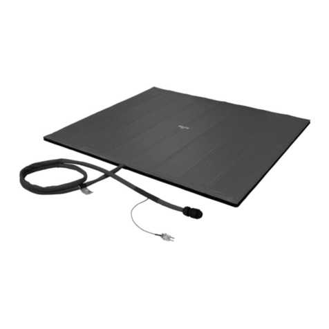
Smith's Heating First PROFILE Series User manual
Other Smith's Heating First Heater manuals

Smith's Heating First
Smith's Heating First SS2E/5 User manual
Smith's Heating First
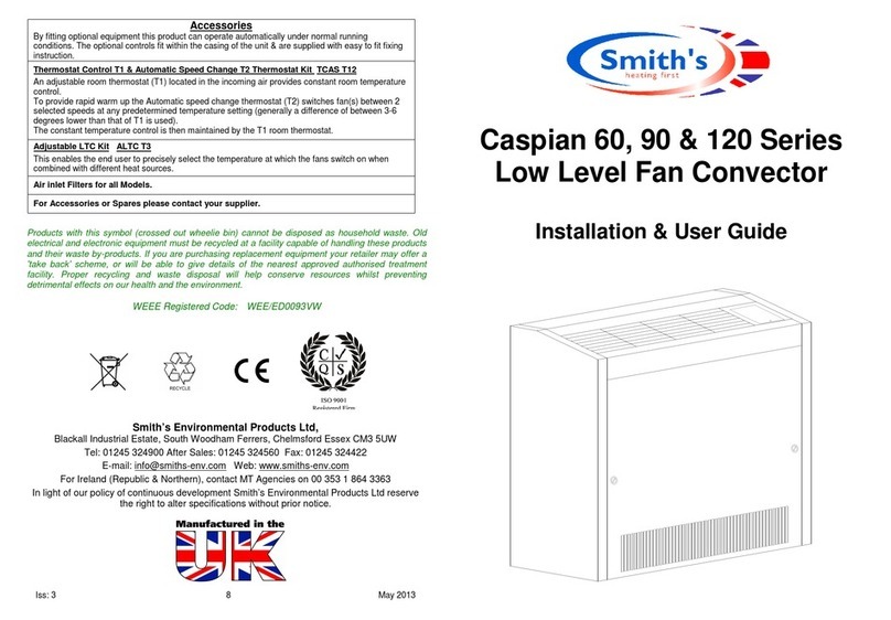
Smith's Heating First Caspian 60 Operation manual
Smith's Heating First
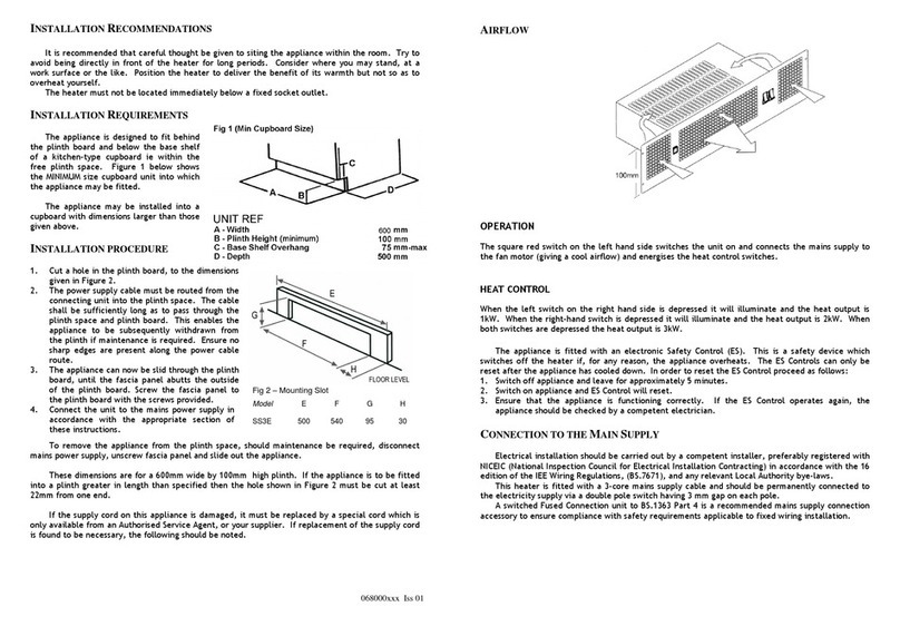
Smith's Heating First SS3E User manual
Smith's Heating First
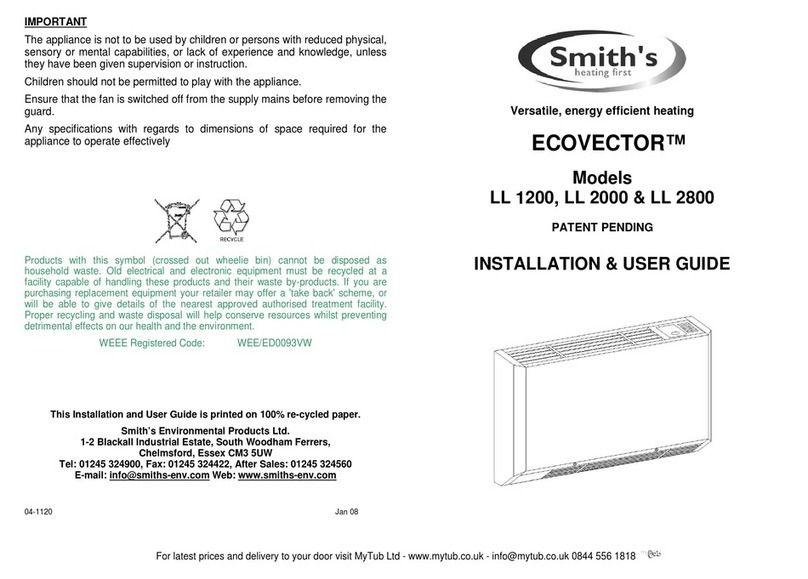
Smith's Heating First ECOVECTOR LL 1200 Operation manual
Smith's Heating First
Smith's Heating First Caspian 60 Operation manual

Smith's Heating First
Smith's Heating First Ostro Guide

Smith's Heating First
Smith's Heating First Eco-Powerad 500 Operation manual
Smith's Heating First
Smith's Heating First Signature Operation manual

Smith's Heating First
Smith's Heating First SS5/Dual User manual
Smith's Heating First
Smith's Heating First PWU 4/6 Operation manual
Smith's Heating First
Smith's Heating First Solano Guide
Smith's Heating First
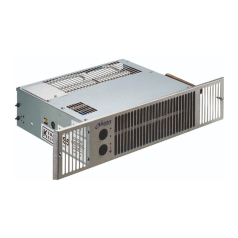
Smith's Heating First Space saver SS7 User manual
Smith's Heating First
Smith's Heating First SS80E User manual

Smith's Heating First
Smith's Heating First STR7-12V User manual

Smith's Heating First
Smith's Heating First External Control Harness Caspian UVC User manual
Smith's Heating First
Smith's Heating First Caspian EC Series Guide

Smith's Heating First
Smith's Heating First Caspian 60 Operation manual
Smith's Heating First
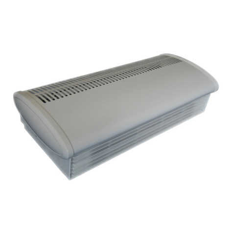
Smith's Heating First Sterling 3 EL Operation manual
Popular Heater manuals by other brands

Qlima
Qlima R122C operating manual

OCI
OCI OCIE48EH Installation & operation guide
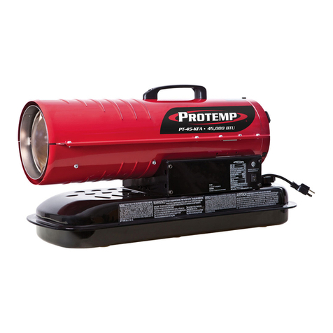
Protemp
Protemp PT-45-KF User's manual & operating instructions

Pinnacle International
Pinnacle International MASTER MH-515-120 User's manual & operating instructions

Bimar
Bimar K80.NE Instruction booklet

Costway
Costway EP25439 Instruction booklet
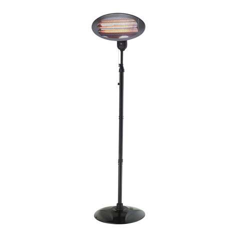
Gabarron
Gabarron IDP Series Installation instructions and user guide

IRSAP
IRSAP Radiator Company Kura Fitting instructions

EUROM
EUROM HI-Tower 2200 Wi-fi instruction manual
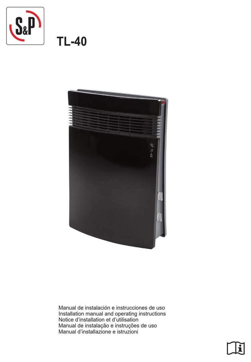
S&P
S&P TL-40 Installation manual and operating instructions

Shini
Shini STM-E Series manual

Clarke
Clarke OFR 9/90 Operation & maintenance instructions


