Smith's Heating First PWU 4/6 Operation manual
Other Smith's Heating First Heater manuals
Smith's Heating First
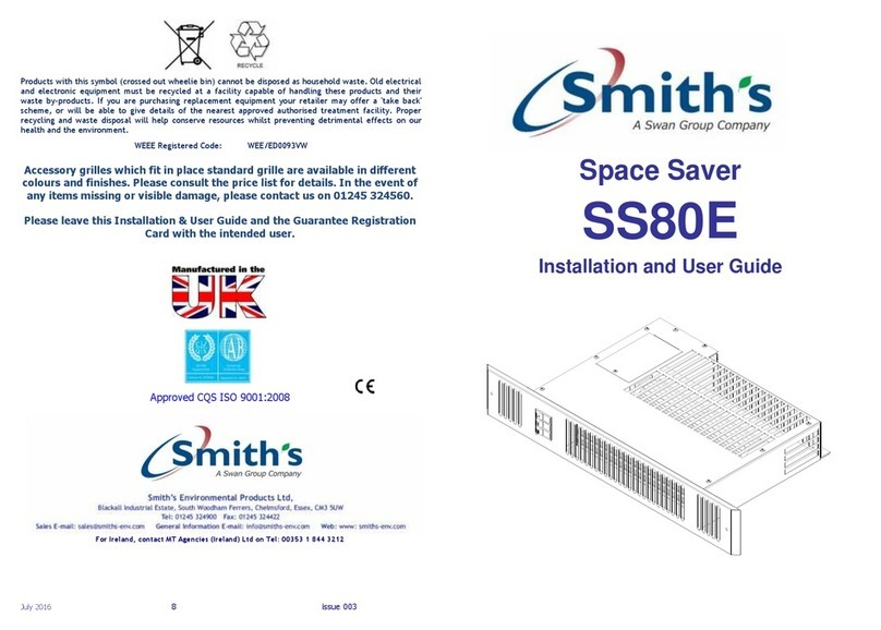
Smith's Heating First SS80E User manual

Smith's Heating First
Smith's Heating First Caspian 60 Operation manual

Smith's Heating First
Smith's Heating First External Control Harness Caspian UVC User manual
Smith's Heating First
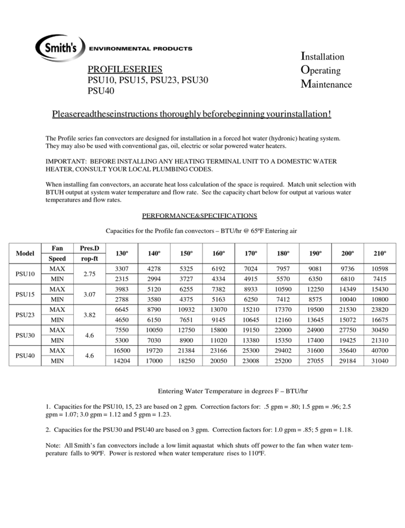
Smith's Heating First PROFILE Series User manual

Smith's Heating First
Smith's Heating First Caspian 60 Operation manual

Smith's Heating First
Smith's Heating First Eco-Powerad 500 Operation manual
Smith's Heating First
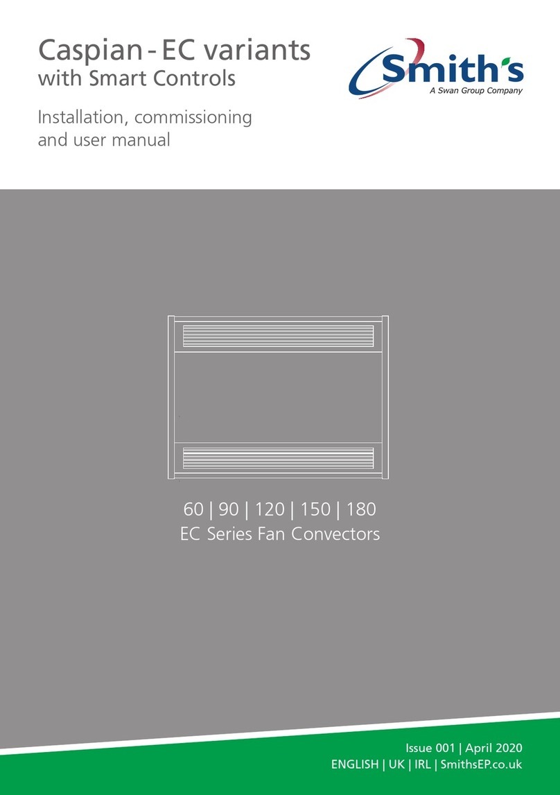
Smith's Heating First Caspian EC Series Guide

Smith's Heating First
Smith's Heating First SS2E/5 User manual
Smith's Heating First
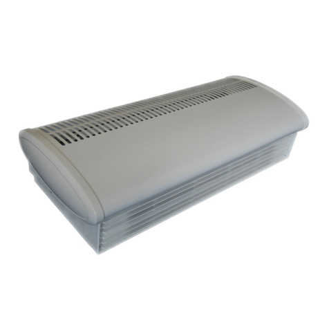
Smith's Heating First Sterling 3 EL Operation manual
Smith's Heating First
Smith's Heating First Caspian 60 Operation manual

Smith's Heating First
Smith's Heating First Ostro Guide
Smith's Heating First
Smith's Heating First ECOVECTOR LL 1200 Operation manual
Smith's Heating First
Smith's Heating First Space saver SS7 User manual
Smith's Heating First
Smith's Heating First SS3E User manual
Smith's Heating First
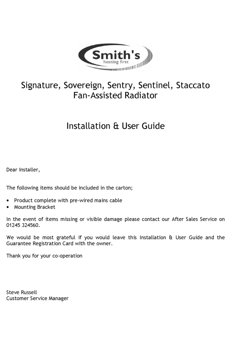
Smith's Heating First Signature Operation manual
Smith's Heating First
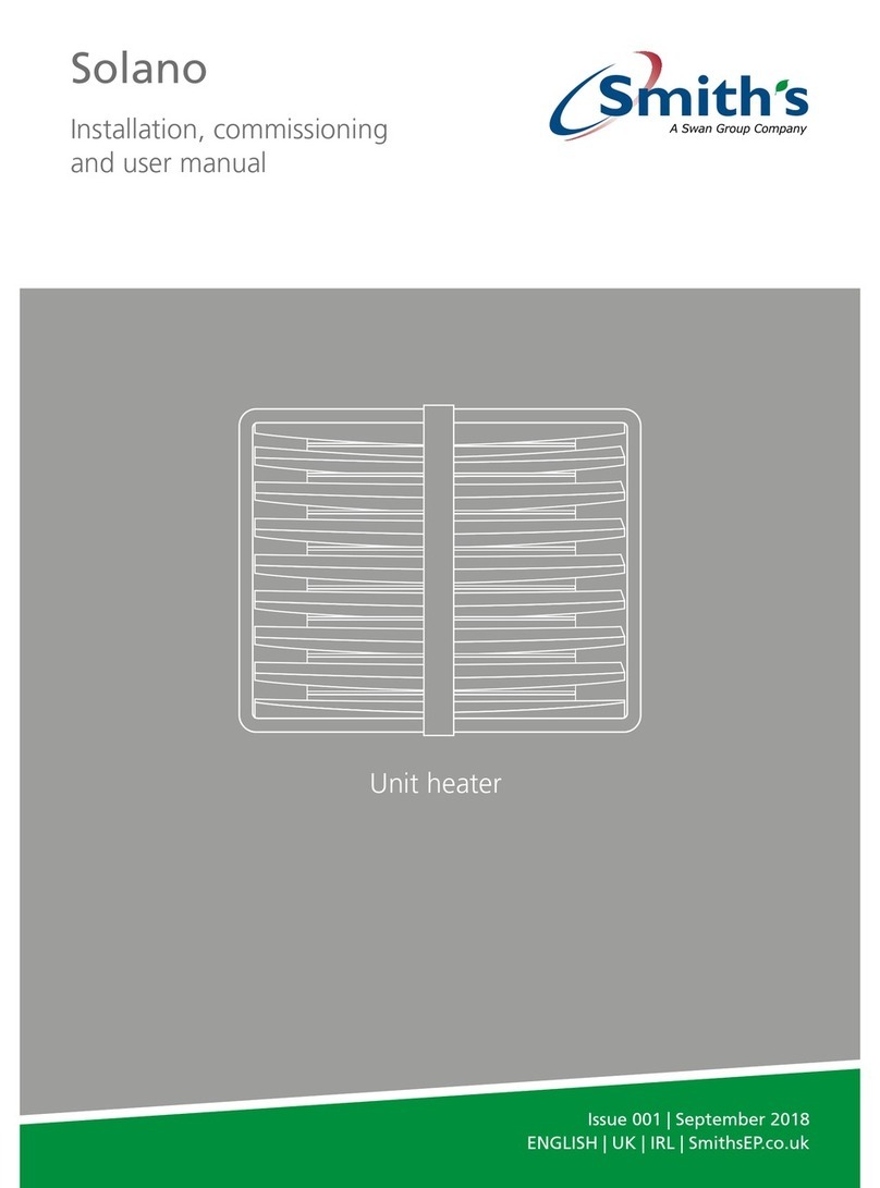
Smith's Heating First Solano Guide
Smith's Heating First
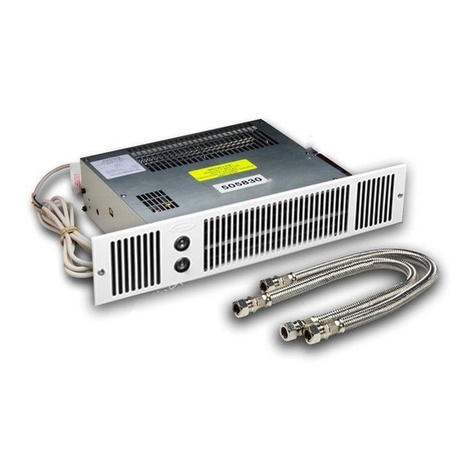
Smith's Heating First SS5/Dual User manual

Smith's Heating First
Smith's Heating First STR7-12V User manual
Popular Heater manuals by other brands

Webasto
Webasto HL 90 Operating and servicing manual
Challenge
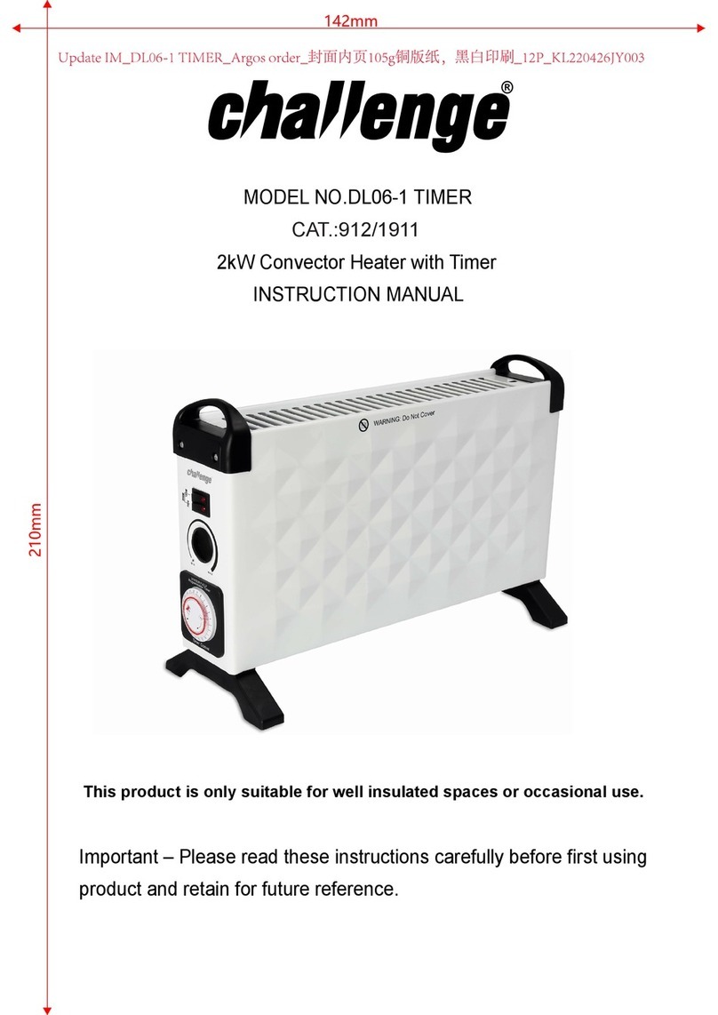
Challenge DL06-1 TIMER instruction manual

Consort
Consort PHSL2 Series Installation & Control Guide

GÜDE
GÜDE GSH 500 K mini Translation of the original operating instructions
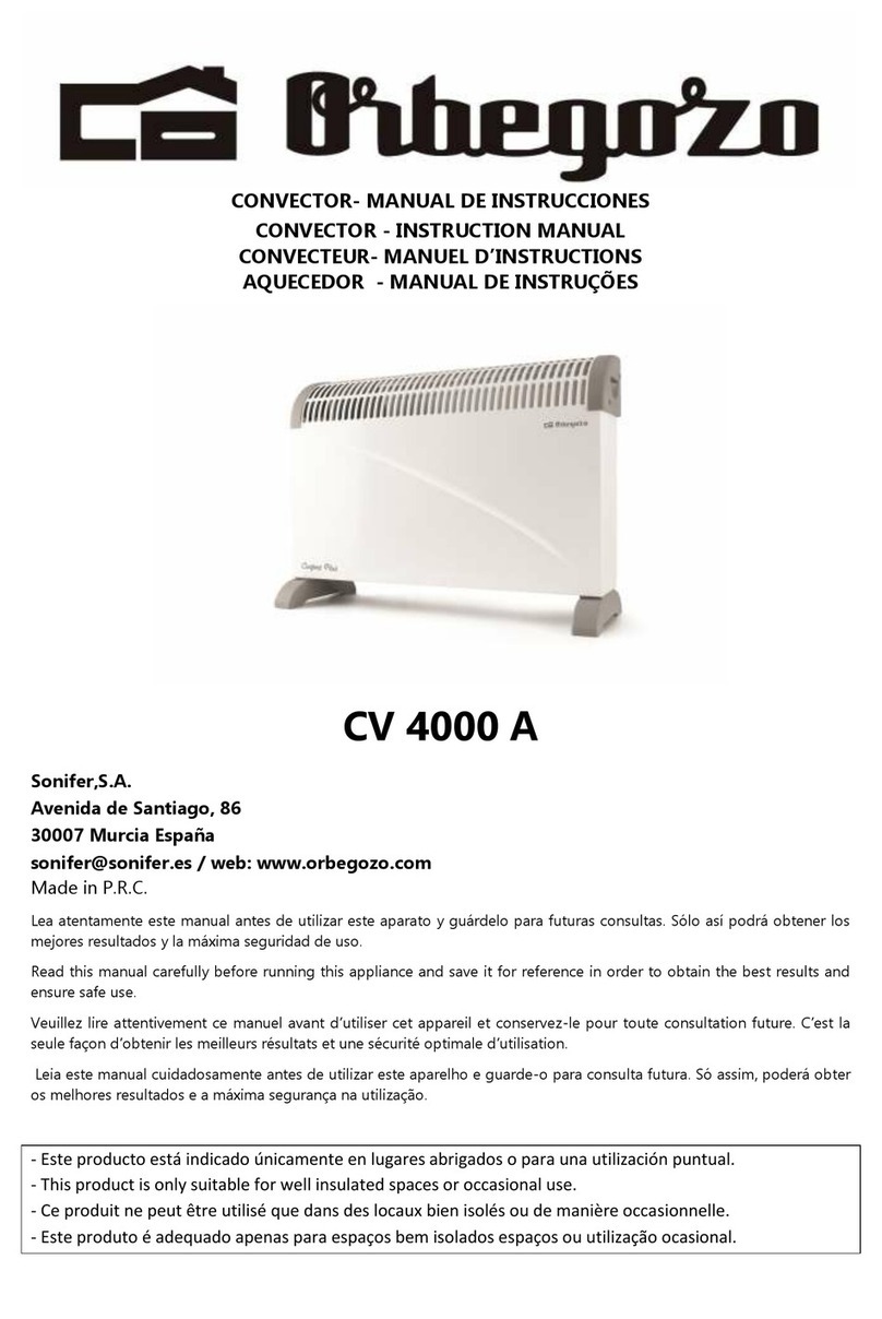
Orbegozo
Orbegozo CV 4000 A instruction manual

Castle Heaters
Castle Heaters KMH-30 instruction manual
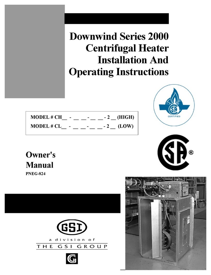
GSI Group
GSI Group 2000 Series Installation and operating instructions

Zephyr
Zephyr Z-1970-Y instruction manual

hylite
hylite SLIMLINE ECO HEATER Assembly & fitting instructions

Phillips & Temro industries
Phillips & Temro industries FLOWSTART FS user guide

CLIMAMEISTER
CLIMAMEISTER IR 20 T instruction manual

MILL
MILL CO1200WIFI3 Assembly and instruction manual


