9102020 iss2
PROTECTION
The unit is protected in the event of fan failure, or an obstruction of the free
airflow, by a single thermal PTC Self Hold Cut-out. Having tripped, the PTC
Cut-out remains open, effectively switching off the heating elements as long
as mains power is available inside the appliance. The PTC Cut-out will only
reset when the appliance is switched OFF and allowed to cool for at least 20
minutes.
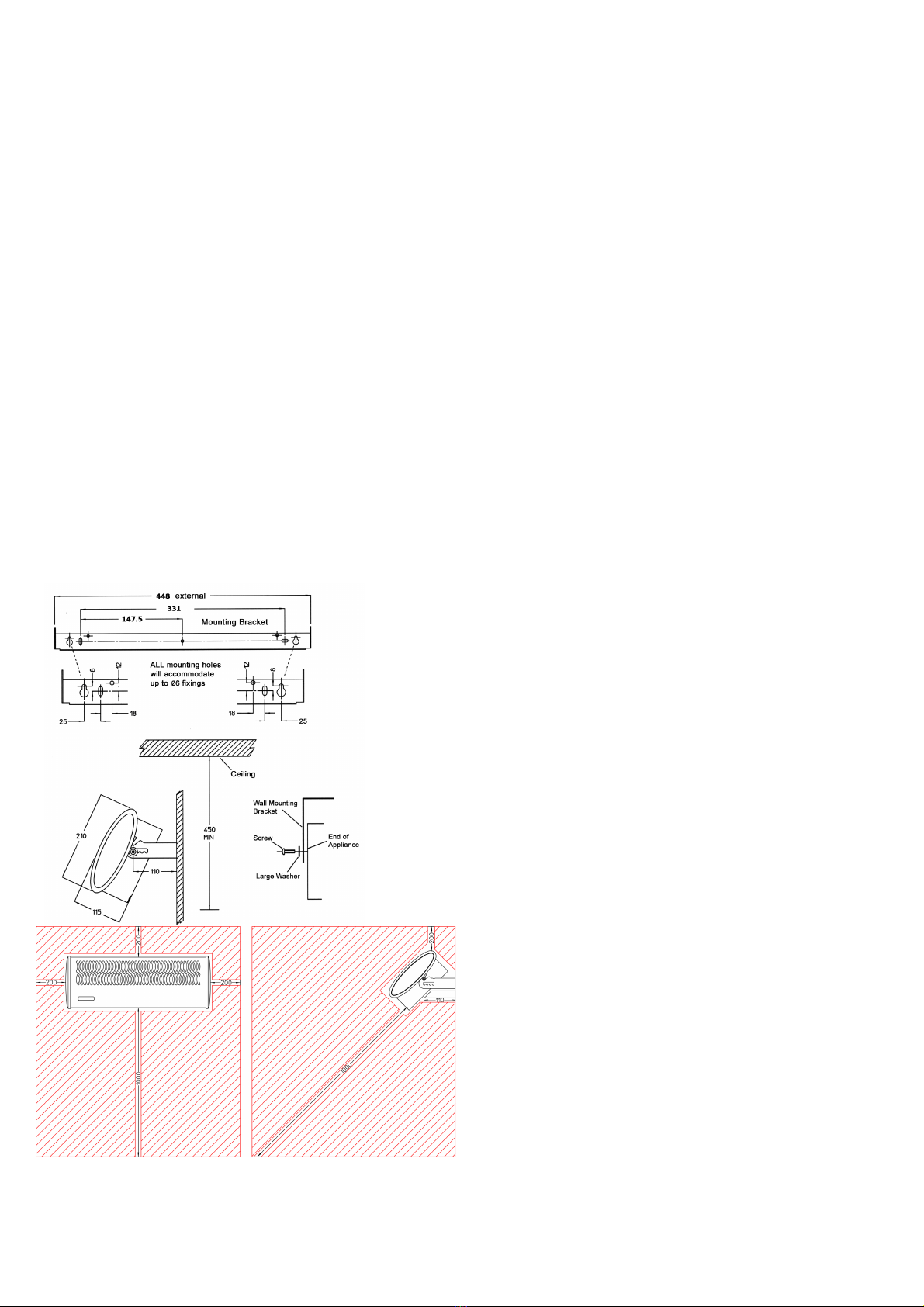
MOUNTING
The normal mounting height is 2.3m above the floor, although this will
depend to some extent on the situation. The unit should be mounted at
least 200mm below ceiling. The heater can be arranged to blow air at any
angle, from horizontal to vertically downwards, subject to the conditions
mentioned below. It is suggested that an angle of 45 deg is a convenient
starting point when setting up the unit. It must always be installed with the
axis of the motor horizontal. Failure to ensure this will result in excessive
bearing wear and premature failure.
A mounting bracket is provided for mounting to a wall.
The heater should not be mounted in situations where it may be subject to
conditions of excessive humidity or the atmosphere is corrosive.
INSTALLATION
IN ALL CASES, THE UNIT SHOULD BE WIRED IN ACCORDANCE WITH IET
REGULATIONS FOR THE ELECTRICAL EQUIPMENT OF BUILDINGS.
Loosen mounting screws, allowing the mounting bracket to be removed from
the unit. Making sure that the mounting bracket is horizontal, fix the bracket
to the wall using 3 x No 8 wood screws.
Place the unit on the mounting bracket ensuring the washers are spaced as
on diagram.
Tighten screws to hold the unit at the required angle.
ELECTRICAL CONNECTIONS
This unit is suitable for connection to a 230/240V 50Hz single phase AC
supply. The unit consumes 3kW of electrical power when the fan and heater
are in operation. Connection to the mains supply should be via a switched
fused isolator.
To connect a supply to the heater the curved top cover first needs to be
removed. Looking directly at the output grille the top cover is secured by two
screws which are located at the upper left and right of the outlet grille. Once
the 2 screws are removed the curved top cover can be removed by lifting it
up and away from the output grille, then lifting off the cover from the two
slot hinges located at the opposite side to the two screws/output grille. The
input terminal block, marked ENL, is fitted at the left-hand side of the unit
looking from above (at the opposite end to the fan motor).
To the unit connect a suitable length of 3 core 1.5 mm2 flexible cable to the
input terminal block marked ENL.
For safety reasons, a sound earth connection MUST ALWAYS be made to the
unit before being used.
Controller
The unit is supplied with a SLVT-B wireless controller. This controller must be
used in conjunction with the heater.
Important: The heater will not function without the controller.
The controller should be positioned 1.5m above the floor and in the same
room as the heater. The controller should be fixed to the wall. Avoid areas
with draft or direct sun. Do not position the controller above or close to the
heater or other heat sources. Damp areas or areas where the controller can
be mechanically damaged should also be avoided. Avoid installing the
controller in areas where there are metal objects between the heater and
the controller. This will reduce the RF range. The RF range in ideal conditions
can be up to 20m however this can be reduced when the signal is passing
through the walls or other objects. The range can be also affected where the
controller is mounted close to power cables, motors or equipment producing
strong electromagnetic field. If the temperature control feature is used it is
necessary to use one controller for each room or zone.
TO RESET THE PTC SELF HOLD CUT-OUT
DO NOT ADJUST BY HAND ANY INTERNAL COMPONENTS
a) The cut-out is reset by switching OFF mains power to the appliance.
b) Allow the appliance to cool for 20 minutes
c) Reconnect mains power, switch ON the appliance.
d) If the cut-out trips again the appliance and installation should be
checked by a qualified electrician.
TO REPLACE A SWITCH
a) Ensure mains supply is switched off.
b) Remove the top cover.
c) Remove the push-on connectors, noting their position.
d) Remove copper links, noting their position.
e) Remove switch by compressing the plastic retaining tabs and lifting out
the switch.
f) Insert the new switch, refit copper links and push on connectors in the
correct order.
g) Test and reassemble.
TO REPLACE THE FAN HEATER ASSEMBLY
a) Ensure mains supply is switched off.
b) Remove the top cover.
c) Disconnect the internal wiring from the main terminal block.
d) Remove the four nuts and washers fixing the fan heater assembly and
earth tag to the back of the case.
e) The fan heater assembly can now be eased forward and removed from
the heater case.
f) Fit replacement fan heater and reassemble in reverse order.
IF YOUR HEATER DOES NOT WORK
• Check that the unit is wired correctly
• Check that the fuse has not blown in the connection to the unit
• Check re-set of PTC (as described under relevant section)
• Check the SLVT-B controller is calling for heat.
• Check the unit is paired with the SLVT-B controller
• Check the battery condition in the SLVT-B controller and replace if
necessary
Do NOT attempt to repair the heater yourself
Should none of the above remedies work, disconnect heater from power
supply and consult accredited service agent. If the appliance is still under
guarantee, return it to your supplier.


