Smoke Guard 600 User manual

1
Model 600 |Installation Manual
Smoke Curtain
287 N. Maple Grove. Boise, ID 83704
P. (800) 574-0330 F. (208) 639-7851
info@smokeguard.com

Doc #601 – M600 Installation Manual Rev. 4
2
Contents
1.0 – Introduction..............................................................................................................................................3
2.0 – System Overview .....................................................................................................................................5
2.1 – Major Components ........................................................................................................................... 6
2.2 – Optional Components....................................................................................................................... 7
3.0 – Install Preparation ....................................................................................................................................8
3.1 – Verify Field Preparation ................................................................................................................... 8
3.2 – Preparing the Housing for Mounting................................................................................................ 9
4.0 – Mounting the Housing and Auxiliary Rails...........................................................................................10
4.1 – Installing the Mounting Plate.......................................................................................................... 10
4.2 – Installing the Housing..................................................................................................................... 12
4.3 – Installing Auxiliary Rails................................................................................................................ 14
5.0 Installing the Screen .................................................................................................................................17
5.1 – Installing the Screen ....................................................................................................................... 17
5.2 – Installing the Screen Rewind Switch.............................................................................................. 21
5.3 – Re-attaching the Housing Door ...................................................................................................... 22
5.4 – Anchoring the Magnets................................................................................................................... 23
6.0 – Calibration & Testing ............................................................................................................................24
6.1 – Calibrating the System.................................................................................................................... 24
6.2 – Testing the Installation...........................................................................................................................25
7.0 – Finishing the Installation .......................................................................................................................27
7.1 – Preparing the Unit for Wiring ......................................................................................................... 27
7.2 – Setting the unit in a ready state....................................................................................................... 27
8.0 – Contact Smoke Guard............................................................................................................................28
9.0 – Glossary .................................................................................................................................................29
Appendix A: Suggested Mounting Plate Anchors.................................................................................................31
Appendix B: Wiring Diagrams ..............................................................................................................................32
Appendix C: Troubleshooting a System Fault.......................................................................................................34

Doc #601 – M600 Installation Manual Rev. 4
3
1.0 – Introduction
This is the official installation manual for the Model 600 Smoke Curtains from Smoke Guard, Inc.
The Smoke Guard Model 600 Smoke Curtain is a motorized smoke protection systems housed above an
elevator. The M600 system is rated to UL 1784 according to the requirements of smoke and draft control
assemblies defined in NFPA 105.
The smoke detector or other initiating device is part of the building smoke and fire alarm system and not a
component of the Smoke Guard system. In the event of an alarm, the initiating device signals the controller to
activate a DC motor to deploy a protective curtain. The curtain unrolls to the floor with the curtain magnets
adhering to either the elevator frame or auxiliary rails to seal the opening. When not in use, the M600 is
retracted into a housing unit which maintains the aesthetic of the facility in which it is installed.
For information about the Model 600 and building codes, see the Model 600 Operation and Maintenance
Manual.
The M600 is fitted with a backup battery. It is designed to prevent fault deployments in the event of AC power
loss.
NOTE: The battery is for emergencies only.
Installation of the Smoke Guard system must be performed by a Smoke Guard factory recognized installer. The
installation requires a moderate amount of construction and electrical experience, as well as the use of tools and
hardware, both standard and specialty. It should only be attempted by factory recognized installers, who have
prior training on the system installation and calibration processes.

Doc #601 – M600 Installation Manual Rev. 4
4
Below is a list of tools and hardware required in addition to the material supplied by Smoke Guard:
•25-foot tape measure
•Permanent marker
•Portable hand drill or driver
•Portable angle-head drill or attachment (for hard-lid installations)
•Drill bits (1/8” for rivets, remaining sizes depend on anchors utilized)
•#2 Philips bit
•Flat and Philips head screwdrivers
•Hand riveter
•Chalk line
•4-foot magnetic level
•Torpedo level
•Tin snips
•Portable bandsaw
•Wire strippers
•Utility knife
•5/16” and 7/16” combination wrenches
•3/32”, 1/8”, 5/32”, 5/16” ball head hex wrenches
•Grounded extension cord
•Screen mounting brackets (J-hooks, available for purchase from Smoke Guard)
•Mounting plate anchors suitable for backing (qty. 6, see Appendix A for suggested anchors)
•Plastic shims for leveling housing
•Rail backer anchors suitable for backing (qty. 10, see Appendix A for suggested anchors)
Installation should occur after the installation of the elevator frame and surrounding drywall, but prior to ceiling
installation and any painting around the elevator.
NOTE: Follow applicable safety procedures during installation, including the appropriate use of any personal
protective equipment (e.g., hard hat, safety goggles, gloves, etc.). Exercise caution when using a ladder or
stepladder and ensure you get assistance and use proper lifting techniques when carrying and mounting the
housing.

Doc #601 – M600 Installation Manual Rev. 4
5
2.0 – System Overview
The M600 Smoke Curtain is a motorized smoke protection system housed in the ceiling of a building. The
system uses a DC motor to deploy a specialized curtain into a strategic location. When not in use, the M600 is
retracted into a housing unit, maintaining the aesthetic of the facility in which it is installed.

Doc #601 – M600 Installation Manual Rev. 4
6
2.1 – Major Components
Smoke Detector:The local smoke detector is the recommended initiating device for the M600.
AC Line In:The M600 can be connected to the building 120 VAC or 240 VAC for primary power.
Housing:The M600 housing contains the control, drivetrain, and screen assembly (when retracted). The dust
cover and junction box are integral parts of the housing.
Mounting Plate (not shown):The mounting plate attaches directly to the backing material above the elevator
and provides the mounting interface for the housing.
DuraNet™ Screen Assembly: The transparent screen assembly forms the main smoke protection barrier from
the elevator shaft and allows visibility from the car onto the landing
Kevlar® Cables: The cables connect the screen threshold pulleys to the drivetrain in the housing to allow the
screen to retract and deploy.
Flexible Magnetic Edge: The magnets on either side of the screen assembly secure the screen to the auxiliary
rails or elevator frame. These magnets also allow for push through manual egress if necessary.
Screen Rewind Switch: The Screen Rewind Switch (SRS) allows egress from either side of the screen. When
pressed the screen will temporarily retract into the housing before redeploying.
Auxiliary Rail: Auxiliary rails provide a surface for the screen magnets to adhere to. The M600 can be
optioned to adhere directly to the elevator frame, which does not require the use of full-length
auxiliary rails. In this configuration the auxiliary rails can also be used as stub rails to bridge the gap
from the housing to the elevator frame.
Auxiliary Rail Backer: If auxiliary rails are used, the backer is attached to the mounting surface during install.
Installation Kit (not shown): A variety of installation components is included with each unit. This kit includes
a roll of Kapton® tape for securing the SRS wiring, a bag of hardware for securing the screen and
housing, a pair of housing door clips for holding the door closed before permanent power is attached.
End of Line Diode (not shown): The end of line (EOL) diode allows for monitoring the integrity of the
initiating device circuit. The EOL diode is required for all installations, see the electrical guide for
more information. The EOL diode is shipped inside the housing junction box.

Doc #601 – M600 Installation Manual Rev. 4
7
2.2 – Optional Components
The M600 may be shipped with the following optional components:
•Wall Activation Switch
•Obstruction sensor
•FSCS Compatibility
Doc #601 – M600 Installation Manual Rev. 4
8
3.0 – Install Preparation
3.1 – Verify Field Preparation
Prior to installing the Smoke Guard system, the general contractor prepares the site for installation.
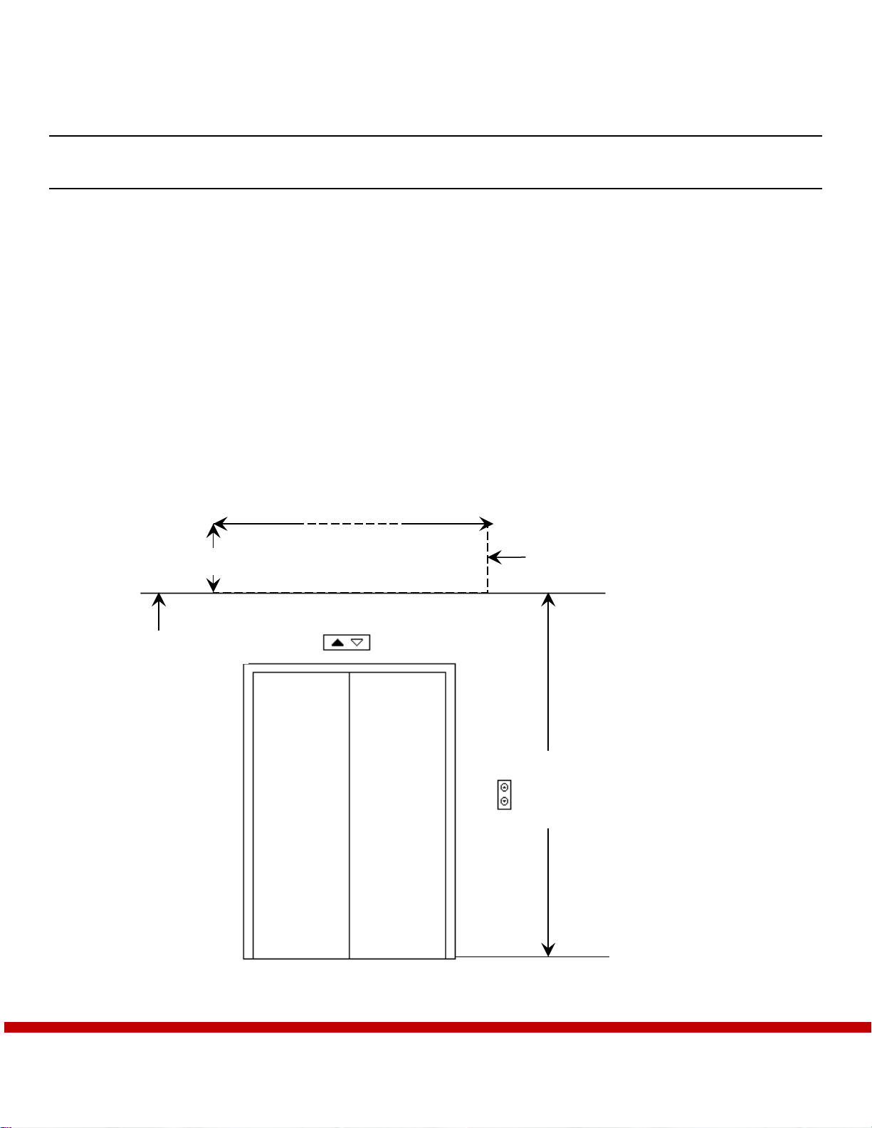
Housing Clearance - For each housing, the general contractor provides a clearance above the elevator:
•Unobstructed, wall plumb, with no distortions
•No more than 10 feet from the floor to the bottom of the housing
•At least 12 inches vertical and 12 inches projected from the mounting surface
•At least 2 inches wider than the housing, centered over the elevator door
•Mounting height marked with a chalk line
•Ceiling and grid removed from housing area
•The backing extending the full width and height of clearance, behind new wall construction or over
existing wall construction
distance frombottom of
housing to floor not to
exceed 10 feet
ceiling height marked
2 inches wider
than hou
sing
12 inches
housing clearance
dimensions, centered over
elevator frame

Doc #601 – M600 Installation Manual Rev. 4
9
Curtain Clearance – For each housing the general contractor provides clearance on the landing side of
elevator:
•Extending from the bottom of the housing to the floor along full curtain assembly width
•Centered over the elevator frame
•Unobstructed, wall plumb, with no distortions
•Free of all obstructions and projections that exceed the housing return depth the full, including elevator
position indicators, signs, and hall call stations
•Includes clearance for door swing; 7-1/4 inches
•With 2 inch wide backing for auxiliary rail backers extending the full height, behind new wall
construction or over existing wall construction
3.2 – Preparing the Housing for Mounting
Visually inspect the housing components, screen, and any electronics for damage. Contact Smoke Guard if any
damage is discovered.
The screen assembly ships inside the housing. Using the door key, carefully remove the screen from the housing
to avoid damaging the screen and/or the housing components. Removing the housing door prior to mounting the
unit will allow for easier installation.
Removing the housing door:
1. Remove screws holding door rod on one side of the housing door.
2. Pull rod out enough to remove the door.

Doc #601 – M600 Installation Manual Rev. 4
10
4.0 – Mounting the Housing and AuxiliaryRails
4.1 – Installing the MountingPlate
The housing holds the curtain, control, battery, and the motor assembly for the Model 600 unit. The housing sits
on a mounting plate, which you fasten to the wall over the elevator frame through predrilled holes.
Required parts, tools, and hardware:
•Mounting plate
•25-foot tape measure
•Torpedo level
•Chalk line
•4-foot magnetic level
•Permanent marker
•Corded or cordless hand drill or driver
•Drill bits for mounting plate anchors
•Mounting plate anchors (see Appendix A for recommended fasteners)
•Plastic shims for leveling housing
Predrilled holes on
mounting plate

Doc #601 – M600 Installation Manual Rev. 4
11
Installing the mounting plate:
1. If NOT already marked by the general contractor, mark the housing mounting height over the elevator
door.
2. If fastening to wall studs, mark the location of the wall studs.
3. Draw a level line ¾” inch above the housing mounting height. This marks where the lower edge of the
mounting plate sits.
4. Mark the center of the elevator frame at mounting height and a centerline on the mounting plate
5. Center the housing over the elevator door using the two centerlines previously drawn or, if fastening
through wall studs, align predrilled holes on the mounting plate with wall studs.
NOTE: If fastening through studs, it is not necessary to center the mounting plate precisely over the elevator
frame if the housing itself is centered and covers the plate completely.
6. Align the bottom of the mounting plate with the line you marked in step 3.
7. Level the plate horizontally and flush against the wall.
8. Mark and drill holes for fasteners.
9. Drill at least 8 holes--4 through the top row of predrilled holes and 4 through the bottom row.
10. Drive fasteners through the holes, fastening the mounting plate to the wall.
11. Verify that the mounting plate is LEVEL and FLAT against the wall.
Anchor the mounting plate so
the bottom sits ¾” above where
you want the bottom of the
housing to sit.

Doc #601 – M600 Installation Manual Rev. 4
12
4.2 – Installing the Housing
Required parts, tools, and hardware:
•Housing (with curtain assembly removed)
•Permanent marker
•Safety eye wear
•Drill
•#10 x ½ self-tapping pan head screws with 5/16 hex head
NOTE: Always keep your head higher than the housing while mounting. This allows for easier installation and
helps to avoid head injury.
Mount the housing on the mounting plate:
1. Hook the top of the housing return over the beveled edge of the mounting plate.
NOTE: If the housing does not fit over the mounting plate, GENTLY pry along the length of the beveled
edge on the plate just enough to fit the housing tightly over the plate.
2. Verify that the center mark on the housing meets the centerline of the elevator frame.
NOTE: If the center lines do not meet, GENTLY tap the sides of the housing to slide it along the mounting
plate, being careful not to damage the housing.
3. Verify that the housing fits tightly on the mounting plate.

Doc #601 – M600 Installation Manual Rev. 4
13
Anchoring the housing to the mounting plate:
1. Drill through hole in the back of the housing into the mounting plate.
2. Verify that the housing is level, sturdy, and flush with the wall.
3. Drill and anchor through 3 or 4 more holes along the width of the mounting plate.
4. Verify that each anchor is flush and tight against the housing to avoid damage to the curtain.

Doc #601 – M600 Installation Manual Rev. 4
14
4.3 – Installing Auxiliary Rails
Auxiliary rails optional on M600s, depending on the installation. The auxiliary rail backer is anchored to the
wall along the sides of the elevator frame. The auxiliary rail is then attached to the auxiliary rail backer to
create the curtain sealing surface. If the elevator frame is nonferrous, not flat, less than 2 inches wide, or
recessed or flush with the wall, the installation will require auxiliary rails to function properly.
If the elevator frame is ferrous (Smoke Guard recommends the use of 430 Stainless Steel), flat, 14 gauge
minimum, and at least 2 inches wide it can be used as the curtain sealing surface for an M600. In this case you
can utilize stub rails extending from the top of the elevator frame to the bottom of the housing to provide a
continuous seal. Stub rails are attached to a backer that is anchored in place much like an auxiliary rail. Stub
rails are not required if the gap between the head of the elevator frame and the housing is 1/4” or less.
Do not field paint auxiliary rails, housing, or housing door without first contacting Smoke Guard or your
installing distributor.
•Take care to avoid painting the housing door shut.
•Before painting auxiliary rails, you must strip any existing paint to bare metal. Use a paint that is
resistant to 300 degrees Fahrenheit and coat to a maximum thickness of 0.005 inches.
•After painting any components your system must be completely retested to ensure no functional issues
have been created.
NOTE: When taking measurements for the length of the rails, be sure to account for the thickness of the
flooring that may be added later. A floor material sample is ideal to ensure correct measurements.
Required parts, tools, and hardware:
•Auxiliary or stub rail backers
•Auxiliary or stub rails
•Flooring sample if available
•25-foot tape measure
•4-foot magnetic level
•Permanent marker
•Tin snips
•Portable bandsaw
•Hand riveter
•#44 rivets (qty. 16)
•Corded or cordless hand drill or driver
•Drill bits for auxiliary rail backer anchors
•Auxiliary rail backer anchors
•Driver for auxiliary rail backer anchors
•Plastic shims for leveling housing
auxiliary rail with pop-rivet
hole on one of the return
edges
rail mounting channel
fastened to the wall

Doc #601 – M600 Installation Manual Rev. 4
15
Installing the auxiliary rail backers:
1. For auxiliary rails, measure the distance between the floor and the bottom of the housing. For stub rails
measure the distance between the head of the elevator frame and the bottom of the housing.
2. Use the measurement from step 1 to cut the rail backers to length with tin snips.
3. For auxiliary rails drill 4-6 evenly spaced holes on each rail backer for wall anchors. For stub rails drill
at least 2 evenly spaced holes, ideally ~1” from each end of the rail backer.
4. Align the center of a rail backer with the right rail backer centerline marked inside the housing.
5. Level the rail backer vertically.
6. Mark and drill anchor holes in the wall using the rail backer as a template.
7. Drive anchors through the drilled holes to anchor the rail backers in place.
8. Repeat steps 4-7 for the left rail backer.

Doc #601 – M600 Installation Manual Rev. 4
16
Installing the auxiliary rails:
1. Use the height of the right rail backer to determine the cut length for the auxiliary rail.
2. Mark the cut length on the auxiliary rail and use a bandsaw to cut to length. The auxiliary rails are one
of the most visible components, take care to make a clean, level cut.
3. Repeat steps 1 and 2 for the left auxiliary rail.
4. Drill 3-6 evenly spaced holes along the outside edge of each rail. Bias these holes towards the face of the
rail to allow enough room for a hand riveter when installing.
5. Place both auxiliary rails over the rail backers, making sure to orient the factory cut edge against the
housing for a clean interface without any gaps.
6. Hold each auxiliary rail so it is fully seated on the rail backer, flush with the wall, and flush with the
bottom of the housing.
7. Verify that the rails are vertically level.
8. Use the holes drilled in step 4 as a template to drill mating holes in the rail backers.
9. Rivet the auxiliary rails in place.
NOTE: Ensure that the auxiliary rails are mounted such that the rail faces are flush against the back of the
housing and do not protrude, causing an obstacle for the magnet seal.

Doc #601 – M600 Installation Manual Rev. 4
17
5.0 Installing the Screen
5.1 – Installing the Screen
Required parts, tools, and hardware:
•Screen
•Screen mounting brackets (J-hooks, available for purchase from Smoke Guard)
•Installation kit
•Phillips self-drilling screws (qty. 2)
•Corded or cordless hand drill or driver
•#2 Phillips bit
•Motor Jogger (not included, available for purchase from Smoke Guard)
•Grounded extension cord
•5/16” hex driver
Attaching the J-hooks:
1. Clean any debris off the magnets of the J-hooks to avoid scraping the auxiliary rails or elevator frame.
2. Carefully place each hook on its auxiliary rail butted against the outer edge.
3. Line up the tops evenly with each other, at least two inches below the housing, aligning them vertically
so the screen will sit level.
J-hooks

Doc #601 – M600 Installation Manual Rev. 4
18
To set the curtain:
1. Lift the curtain onto the J-clips so that it unrolls from the back.
2. Remove the nut from the center stud.
3. Lift the top bar of the curtain to unroll it up into the housing far enough to fit its center hole over the
center stud and reattach the nut.
4. Grab the magnets near both sides of the top bar and pull outwards so the screen is taut, and the screen
overlaps the auxiliary rails or the elevator frame by 1/4” on each side.
NOTE: The curtain should overlap the rails (or side of the elevator frame in some installations) by ¼” on each
side.
center stud

Doc #601 – M600 Installation Manual Rev. 4
19
Attach the threshold cables:
1. Release the zip tie from the length of cable wound up on each side of the housing.
2. Unwind enough cable to reach the threshold spools.
3. Work the cable through the slots in the spools and pull the cable up, lodging the crimp bead snugly in
the holes.
4. Wrap cable 3 times around the threshold spools, over the top toward the wall, as illustrated:
To position and secure the curtain:
1. Connect one wiring harness from the jogger to the wiring harness from the motor. Only one harness
from the jogger fits the motor harness.
2. Connect the other wiring harness from the jogger to the harness from the battery inside the housing.
3. Press the UP button briefly to jog the curtain up and remove the J-clips.
4. Run the curtain down to the floor.
5. Verify that the magnets cover BOTH rails COMPLETELY and the threshold seals along its FULL
LENGTH at the floor.
6. If necessary, run the curtain back up near the housing and pivot the top bar on the center stud to re-
position the curtain until it seals properly.
7. When the curtain is positioned properly, fasten through each top bar tab with a drill point screw.
8. Run the curtain down to the floor.
Crimp bead
Wind direction

Doc #601 – M600 Installation Manual Rev. 4
20
9. Verify that the magnets cover BOTH rails COMPLETELY and the threshold seals along its FULL
LENGTH at the floor.
10. If necessary, run the curtain back up near the housing and pivot the top bar on the center stud to re-
position the curtain until it seals properly.
11. When the curtain is positioned properly, fasten through each side of the top bar with a drill point screw.
Table of contents
Other Smoke Guard Safety Equipment manuals


Popular Safety Equipment manuals by other brands

Lanex
Lanex PB-20 instruction manual

SKYLOTEC
SKYLOTEC ANCHOR ROPES Instructions for use

Besto
Besto Buoyancy Aid 50N Instructions for use

TEUFELBERGER
TEUFELBERGER NODUS Manufacturer's information and instructions for use

Troy Lee Designs
Troy Lee Designs Tbone Product owners manual

Innova
Innova Xtirpa Instruction and safety manual

bolle SAFETY
bolle SAFETY B810 quick start guide

SHENZHEN FANHAI SANJIANG ELECTRONICS
SHENZHEN FANHAI SANJIANG ELECTRONICS A9060T instruction manual

Hiltron security
Hiltron security POWER8E Installation and use manual

Salewa
Salewa MTN SPIKE user manual

Hatco
Hatco B-950P installation guide

Sitec
Sitec TX MATIC operating manual


