SMS TAKEDO-3VF User manual

TAKEDO- 3VF
HYDROVERT
V20
USER MANUAL
2.1 10-08-2017 R. Bocconi
REV. DATE Check and Approval R.T.

HYDROVERT V20 USER MANUAL Version 2.1 dated 10-08-2017
2
INDEX
1 -
INTRODUCTION Page
3
2 -
RECOMMENDATIONS AND PRECAUTIONS Page
3
3 -
CONNECTION OF THE POWER CIRCUIT Page
4
4 -
CONTROL CIRCUITS Page
5
5 -
BASIC APPLICATION DRAWING
5.1 – OIL TEMPERATURE MEASUREMENT PROBE
Page
Page
6
7
6 -
KEYBOARD AND PROGRAMMING Page
8
7 -
MONITOR MENU Page
9
8 -
PARAMETERS MENU Page
10
9 -
FAULTS MENU Page
12
10 -
ADJUSTMENT PROCEDURE
10.1 – UPWARD RUN Adjustments
10.2 – UPWARD START Adjustments
10.3 – UPWARD STOP Adjustments
10.4 – RE-LEVELLING Adjustments
10.5 – MAXIMUM INPUT POWER Adjustments
Page
Page
Page
Page
Page
Page
14
14
15
15
16
16
11 -
CONTROLS AND MAINTENANCE Page
17
12 -
DIMENSIONS AND FIXING Page
18
VACON DECLARATION OF CONFORMITY Page
19

HYDROVERT V20 USER MANUAL Version 2.1 dated 10-08-2017
3
1 – INTRODUCTION
HYDROVERT V20 is a new inverter model with built-in EMC filter in compliance with 2004/108/EC
(Electromagnetic Compatibility) and 2006/95/EC (Low Voltage) Directives, fitted with special software for
hydraulic systems, which can operate with both old and new control units.
Controls only the UPWARD run phase.
The following advantages are attained:
•No peak currents. The maximum start-up current is the nominal current.
•Possibility of setting a network maximum input power limit, to contain the contractual power.
•Reduction of consumptions.
•Optimisation of run comfort.
•Power factor correction of the network input power. Cosϕ
ϕϕ
ϕ0.98.
•Possibility of selecting the inspection speed value.
HYDROVERT V20 is available for motors with maximum input current up to 27A.
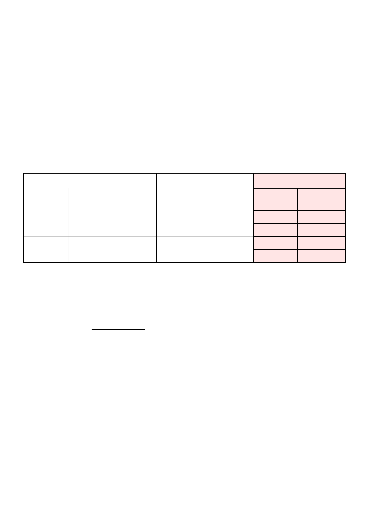
A TABLE is given successively, which states the indicative INPUT POWER and ENGAGED POWER values
that can be obtained with HYDROVERT V20, highlighting the possible saving with respect to the application
of a simple SOFT STARTER.
MOTOR DATA
INPUT POWER
(kW)
ENGAGED
POWER
(kW)
PLATE
POWER
(kW)
NOMINAL
CURRENT
(A)
MAXIMUM
CURRENT
(A)
With
NOMINAL
current
With
MAXIMUM
current
SOFT
STARTER HYDROVERT
2.2 7.1 9 3.9 5 6 4.5
3 8.6 11 4.7 6 6 4.5
4.7 13 16 7.2 8.8 10 6
6 15 21 8.3 11.6 15 6
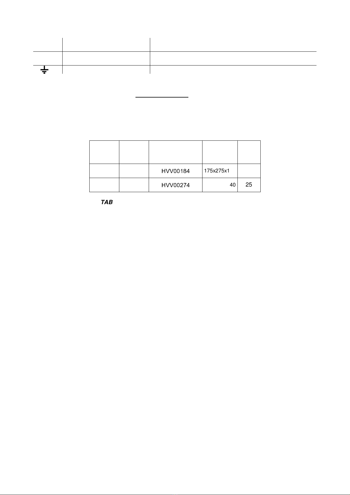
TABLE 1 – Input Power and Engaged Power
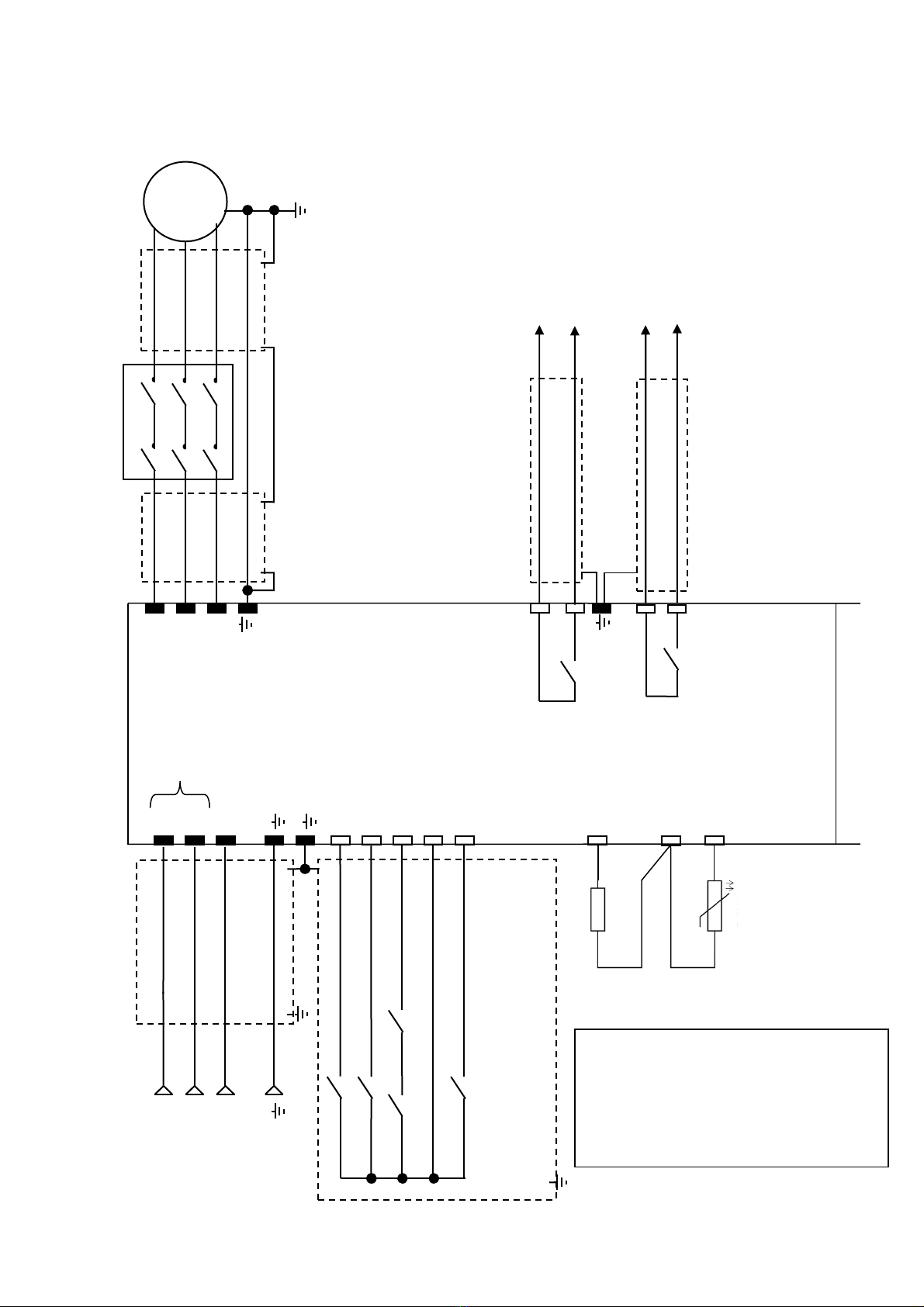
2 – RECOMMENDATIONS AND PRECAUTIONS
For everything that concerns the recommendations relative to personal safety and to prevent accidental
damage to the product or equipment connected to it, refer to the “SAFETY” chapter in the original
VACON INSTALLATION AND MAINTENANCE TECHNICAL MANUAL (VACON 20 Cold Plate series
inverter) available at www.it.vacon.com, where the “Declaration of Conformity”, given on the last page of
this document, is also present.
Read this manual completely before powering the appliance.
Regarding specific application on elevators, also carefully consider the following points:
1- The inverter leakage current to earth is over 30mA, a residual current device must therefore be
envisioned with I
d
no less than 300mA; type B or type A. For the earth connection, the regulations
prescribe a cable with minimum section of 10 mm².
If, on closing the master switch, the RCD intervenes, do not repeat the operation several times
successively because the inverter could undergo permanent damage.
2- To prevent damage to the inverter in the event of prolonged standstill without power supply,
before re-starting it is necessary:
- If the inverter is at a standstill for several months, power it for at least 1 hour in a way to
regenerate the bus condensers.
- If the inverter is at a standstill for more than 1 year, power it for 1 hour with voltage that is 50%
lower than the nominal voltage and then for 1 hour at nominal voltage.

HYDROVERT V20 USER MANUAL Version 2.1 dated 10-08-2017
4
3 – CONNECTION OF THE POWER CIRCUIT
L1;L2;L3 Network power supply input Connect the three power supply network input phases,
independently of the cyclic direction.
U;V;W Inverter outlet Connect the three output phases to the contactors and
therefore to the motor
Earth Connect to the system earth
For the dimensioning of the cables and the position of the terminals, refer to the “POWER CONNECTIONS”
chapter in the original VACON INSTALLATION AND MAINTENANCE TECHNICAL MANUAL (VACON 20
Cold Plate series inverter) available at www.it.vacon.com.
HYDROVERT V20 400 VOLT
RATED
CURRENT
(A)
MAXIMUM
CURRENT
(A)
CODE
DIMENSIONS
LxHxD
(mm)
FUSES
gG/gL
(A)
18 19.6
HVV00184
175x275x140
20
27 29,7
HVV00274
175x275x140
25
TABLE 2 – Currents and fuses for 400V power supply voltage

HYDROVERT V20 USER MANUAL Version 2.1 dated 10-08-2017
5
4 – CONTROL CIRCUITS
Number
Description
1 Control Terminals A-20
2 Terminals STO
3 Relay Terminals
4 Optional Board Terminals
5 Jumpers STO
6 DIP Switch:
SW1 in position 0, the digital inputs common (8-10 and 14-16)
is connected to earth (pre-defined position);
in position 1, the above-mentioned common is isolated from earth.
SW2 analogue input operation AI1;
SW3 analogue input operation AI2;
in position 0, the analogue input selected works in current;
in position 1, the analogue input works in voltage;
the voltage range is 0…10V and current range is 0/4…20mA.
SW4 used for the termination of the bus in the RS485 connection;
in position 0, the termination resistance is connected;
in position 1no (pre-defined position).
7 Status LED:
“PWR” Orange the inverter is powered by the network
“RUN” Green the inverter is in operating mode
“FLT” Red the inverter has an anomaly
“RDY” Orange the inverter is READY and there are no anomalies
it flashes when an alarm is triggered
8
HMI RJ45 connector for control panel (Keyboard/PC)
9 Braking Resistance Terminals (not used for this application)
10 Power supply connector for fan
11 A-20 echo connector

HYDROVERT V20 USER MANUAL Version 2.1 dated 10-08-2017
6
HYDROVERT
V20
U
8
L2
W
V
23
22
16
10
9
TP1
V-SPEED (HIGH/LOW)
S
-
UPWARD
L1
TP
SHIELDED
CABLE
C
ONTACTORS
THREE-
PHASE
LINE
400V
M
3-PH
SHIELDED
CABLE
EARTH CABLE
SHIELDED CABLE
SHIELDED CABLE
RO1
L3
6 24Vdc
S
T
R
SHIELDED CABLE
TP TP1 E-ENABLE
26
25
RO2
INSPECTION
SHIELDED CABLE
CONTACTORS
AND UPWARD/HIGH SPEED VALVE
COMMAND
Imax< 400mA DC; Vmax<=125 Vdc
(see IMPORTANT! note in the box)
INVERTER CONTACT “OK”
Imax< 400mA DC; Vmax<=125 Vdc
1
2
3
5 – BASIC APPLICATION DRAWING
L1-N for the
230V single-phase
connection
1K2 1/4W
TEMPERATURE
PROBE
1000Ω0°C
IMPORTANT!
During the UPWARD run, the HIGH
SPEED electro-valve must be powered
for the entire duration of the run, up to the
end of the electrical stop at the floor
(e.g. through an auxiliary switch of the run
contactors).

HYDROVERT V20 USER MANUAL Version 2.1 dated 10-08-2017
7
5.1 – OIL TEMPERATURE MEASUREMENT PROBE
ASSEMBLY OF THE PROBE INSIDE THE HYDRAULIC CONTROL UNIT
Immerse the bulb of the control unit oil probe, paying attention that it does not touch the bottom but remains
in the oil bath even with the cabin at the extreme top floor.
INVERTER SETTINGS
The ANALOGUE input 1 (terminal 2), must be configured in “VOLTAGE”:
Switch SW2 in position 1
Connect the probe as indicated in the layout
To set the relative parameters, see Paragraph 10.3, points 4 ÷ 11.

HYDROVERT V20 USER MANUAL Version 2.1 dated 10-08-2017
8
6 – KEYBOARD AND PROGRAMMING
The programming keyboard is the interface between
HYDROVERT V20 and the user and must be connected to
the connector shown in the figure, via the cable supplied.
The keyboard can be used to control the state of the motor and the inverter and modify the parameters.
The KEYS section is illustrated in the following figure:
The DISPLAY section indicates the status of the motor and inverter, including any irregularity in operation of
the same.
It is possible to see the information regarding the current position inside the menu and the item displayed.
Go backward through menus.
Exit from the modification
mode. Hold down to reset the
FAULTS
Scroll the menu upwards.
Modify the values,
increasing them.
Scroll the menus downwards.
Modify the values,
decreasing them.
NOT USED
Move the cursor to the
right
Move the cursor to the left
NOT USED NOT USED
Enter the level or active item.
Confirm the selection.
STATUS
indicators
ALARM or FAULT
indicators
MENU
indicators
DIRECTION
indicators
CONTROL POSITION
indicators

HYDROVERT V20 USER MANUAL Version 2.1 dated 10-08-2017
9
6.1 – MENU STRUCTURE
On the keyboard, the data is divided into Menus.
•Use UP ARROW and DOWN ARROW to scroll the menus.
•Enter the desired group by pressing the OK key and go back to the previous level by pressing the
BACK/RESET key.
The arrow on the left of the display indicates the active menu.
The MAIN MENU has the following structure:
Reference from Keyboard
(REF)
Monitor
(MON)
Parameters
(PAR)
Faults
(FLT)
(divided into ACTIVE FAULTS and FAULTS MEMORY)
6.2 – USING THE KEYBOARD
6.2.1 DATA MODIFICATION
To modify the value of a parameter, follow the procedure below:
1. Identify the parameter
2. Press OK to enter the MODIFICATION mode
3. Set the new value using the UP and DOWN ARROWS.
The value can also be modified number by number, moving from one to another using the RIGHT
and LEFT ARROWS.
4. Confirm the modification using the OK key
(or ignore the modification and go back to the previous level by pressing the BACK/RESET key).
6.2.2 RESET FAULTS
When a FAULT appears and the inverter blocks, analyse the causes that led to the intervention of the
protection function with the help of the TABLE in Chapter 9.1 – ACTIVE FAULTS, then restore operation by
pressing and holding the BACK/RESET key.
7 – MONITOR MENU
This menu allows to display values and data during operation of the inverter and is divided into 2 sub-menus.
Index Description Index Description
1 – Motor
V1.1 Output frequency V1.6 Motor power
V1.2 Frequency Reference V1.7 Motor voltage
V1.3 Motor shaft speed V1.8 Motor temperature
V1.4 Motor current V1.9 Final output frequency
V1.5 Motor torque V1.10 Actual Power
2 – Inverter
V2.1 DC-link voltage
V2.7
RO1 RO2 DO1
Contactors Inverter “OK” Inverter “READY”
(terminals 22-23) (terminals 25-26) (terminals 6-20)
V2.2 Unit temperature
V2.8 Analogue output
V2.3 Board temperature V2.9 Anticipated contactors openings
V2.4
DI1 DI2 DI3
Upward Speed
(High/Low)
Enable
(terminal 8) (terminal 9) (terminal 10)
V2.10 Not Used
V2.5
DI4 DI5 DI6
Downward Emergency Inspection
(terminal 14) (terminal 15) (terminal 16)
V2.11 Analogue Input 1
V2.6
DI7 DI8 STO
(terminal 2) (terminal 4) (terminal STO)
------------ NOT USED -----------
V2.12 Analogue Input 2

HYDROVERT V20 USER MANUAL Version 2.1 dated 10-08-2017
10
8 – PARAMETERS MENU
(Default values for 400V series)
Index Description Unit Default Value
1
–
BASIC PARAMETERS
P1.1 Current limit A
(**)
P1.2 Motor nominal voltage V 400
P1.3 Motor nominal frequency Hz 50
P1.4 Motor nominal speed rpm 2800
P1.5 Motor nominal current A
(*)
P1.6 Motor φcos 0.80
P1.7 Identification 0
P1.8 Maximum power kW 15
2
–
CONFIGURATION
P2.1 Pre-start ramp 0.2
P2.2 Pre-start frequency Hz 2.00
P2.3 Pre-start time s 0,1
P2.4 Acceleration time s 1,5
P2.5 Deceleration time s 2,0
P2.6 High speed Hz 50
P2.7 Low speed Hz 7
P2.8 Levelling speed Hz 7
P2.9 Inspection speed Hz 25
P2.10 Final deceleration time s 0,5
P2.11 Ramp shape s 2,00
P2.12 Losses compensation rpm 0
P2.13 No-load current A
(*)
P2.14 Max load current A
(*)
P2.15 Load compensation Hz 2
P2.16 Oil temperature compensation Hz 0
P2.17 Power measure % % 150
P2.18 Power measure Hz Hz 20
P2.19 Current increment with speed % 30
P2.20 Decel time correction in power limit % 120
P2.21 Minimum load threshold % 50
P2.22 Short floor speed Hz 20
P2.23
Levelling compensation minimum Hz 0
P2.24
Levelling compensation maximum Hz 1
P2.25
Levelling minimum current A
(*)
P2.26
Levelling maximum current A
(*)
3
–
DRIVE CONTROL
P3.1 Brake chopper 0
P3.2 Brake chopper threshold V 0
P3.3 Motor control mode 1
P3.4 Switching frequency kHz 8.0
P3.5 Torque boost 1
P3.6 U/f ratio selection 2
P3.7 Field weakening point Hz 50
P3.8 Voltage at field weakening point % 100
P3.9 U/f curve midpoint frequency Hz 1.75
P3.10 U/f curve midpoint voltage % 5.00
P3.11 Output voltage at zero frequency % 3.50
P3.12 Identification current % 50
P3.13 Motor stator voltage drop % 0.00
P3.14 Low switching frequency kHz 5.0
P3.15 Change switching frequency threshold Hz 5.00
P3.16 Low noise modulator 1
P3.17 Power limit correction % 100
P3.18 Current 2nd read delay s 0,5
P3.19 Power limit mode 1
P3.20 Stable current window 0,20
(*) The value depends on the inverter size and is set on the basis of the type of motor and lift system.
(**) The value depends on the inverter size.

HYDROVERT V20 USER MANUAL Version 2.1 dated 10-08-2017
11
Index Description Unit Default Value
4
–
INPUT SIGNALS
P4.1 Upward start 1 (DI1)
P4.2 Downward start 4 (DI4)
P4.3 High speed 2 (DI2)
P4.4 Inspection speed 6 (DI6)
P4.5 Run enable 3 (DI3)
P4.6 Emergency 5 (DI5)
P4.7 A3 mode door 0
P4.8 A3 mode bottom floor 0
P4.9 Short floor 0
5
–
OUTPUT SIGNALS
(see BELOW for CONFIGURATION)
P5.1 Relay output 1 content 3
P5.2 Relay output 2 content 1
P5.3 Digital output 1 content (Open Collector) 1
P5.4 Analogue Output digital function content 1
P5.5 Relay output 1 ON delay s 0.00
P5.6 Relay output 1 OFF delay s 0.00
P5.7 Relay output 1 inversion 0
P5.8 Relay output 2 ON delay s 0.00
P5.9 Relay output 2 OFF delay s 0.00
P5.10 Not Used
P5.11 Not Used
P5.12 Not Used
P5.13 Analogue output function 0
P5.14 Analogue output minimum 0
P5.15 Analogue output scale % 100.0
P5.16 Analogue output filter time s 0.0
P5.17 Frequency supervision 1 1
P5.18 Frequency supervision value 1 Hz 30.00
6
–
PROTECTIONS
P6.1 Earth fault protection 2
P6.2 Motor stall protection 0
P6.3 Motor stall delay s 5.0
P6.4 Motor stall minimum frequency Hz 15.00
P6.5 Thermal protection of the motor 0
P6.6 Motor ambient temperature C 40
P6.7 Motor cooling factor at zero speed % 40.0
P6.8 Motor thermal time constant M 45
P6.9 Response to thermistor fault 2
P6.10 Maximum contactor fault numbers 20
P6.11 STO Alarm 1
P6.12 Response to input phase fault 0
P6.13
Input phases fault max. ripple 0
P6.14
Enable OFF check 1
P6.15 Parameters lock 0
CONFIGURATION OF DIGITAL OUTPUT SIGNALS
The digital outputs (relays, Open Collector) and the analogue output used as digital (P5.1 ÷ P5.4) can
assume the following functions:
0 = Fault 4 = Frequency supervision
1 = Ready 5 = Upward start
2 = Valve 1 6 = Valve 2
3 = Motor contactors 7 = No Fault
NOTE: When an output is programmed as frequency supervision (e.g. to control motor speed), the
parameters that indicate the output switching values are:
P5.17 = 0 No supervision
= 1 Output ON at frequency lower than P5.18 (Default)
= 2 Output ON at frequency higher than P5.18
P5.18 = Frequency value at which switching takes place (Default = 30Hz)

HYDROVERT V20 USER MANUAL Version 2.1 dated 10-08-2017
12
Index Description Unit Default Value
7
–
AUTORESET
P7.1 Automatic restart 1
P7.2 Trial time s 60.0
P7.3 Wait time s 3.0
P7.4 Automatic restart trials 3
8
–
EVACUATION
P8.1 Maximum frequency Hz 5.00
P8.2 Switching frequency kHz 3.0
9
–
TEMPERATURE
P9.1 Oil temperature measure 1
P9.2 Initial inverter min. temperature C 10
P9.3 Initial inverter max. temperature C 70
P9.4 Initial motor max. temperature % 80
P9.5 Min. analogue signal % 46
P9.6 Max. analogue signal % 54
P9.7
Zero analogue signal % 50
P9.8
T Min compensation Hz 0.00
P9.9
T Max compensation Hz 0.00
P9.10
T Zero compensation Hz 0.00
10
–
AMENDMENT A3
P10.1 Logic A3 active 0
P10.2 Check interval M 240
P10.3 Closed door time + bottom floor time M 1
P10.4 Valves activation time s 5
P10.5 Check time out M 480
P10.6 EV1 ON delay s 0.15
P10.7 EV2 OFF delay s 0.15
9 – FAULTS MENU
ACTIVE FAULTS and the FAULTS MEMORY are found in this MENU.
9.1 ACTIVE FAULTS
When a fault occurs, the display shows the relative code flashing.
The most common fault messages are listed below. Do not restore the alarm or the fault before having
analysed the causes that have led to the intervention of the protection function.
Always remove the run command before resetting the fault.
Press and hold the BACK/RESET key to restore operation.
9.2 FAULTS MEMORY
The last 10 faults occurring are stored in the FAULTS MEMORY.
Select the FLT Menu, moving the indicator on the left, an S will appear.
Press OK and then the LEFT arrow until F6.1 is displayed: this is the first fault in the memory, i.e. the last
that occurred in time. Press OK to display the KEY.
Press BACK/RESET to go back to F6.1 and then DOWN ARROW to pass to the successive fault F6.2, and
so on to scroll all faults memorised.

HYDROVERT V20 USER MANUAL Version 2.1 dated 10-08-2017
13
Fault
Code Description
1 Overcurrent: The inverter has detected a current that is too high.
2 Overvoltage: The DC intermediate circuit voltage has exceeded the limits envisioned.
3 Earth fault: The measurement of the current has detected that the sum of the motor phases
currents is different to 0, therefore there is a possible current to earth.
5 Load contact: The load contact is open when the START command is active.
8 System fault: Component fault. Faulty operation. No braking resistance connection.
9 Undervoltage: The DC intermediate circuit voltage is below the envisioned voltage limits.
11 Output phases: No current on one or more output phases.
The test is performed 3 times, on the 4th it goes into FAULT mode
13 Inverter undertemperature: The temperature of the heat dissipater is below –10°C.
14 Inverter overtemperature: The temperature of the heat dissipater is above 90℃.
15 Motor stall: The motor stall protection has triggered.
16 Motor overtemperature: The inverter motor temperature model has detected overheating of the
motor. The motor is presumably overheated.
17 Motor underload: The motor underload protection has triggered.
22 "checksum" error: Parameters recovery from EEPROM failed. ℃℃Component fault.
24 Meter fault: The value displayed by the meters is incorrect.
25 "Watchdog" fault: Microprocessor fault.
34 Internal bus communication
39 Device removal: The optional board or the power unit has been removed.
40 Device unknown: Optional board or power unit unknown.
41 IGBT temperature: The IGBT overtemperature protection device has detected a short term
overload current that is too high (motor loaded that does not start).
44 Device modification: The optional board has been changed.
45 Device addition: The optional board has been added.
50 The corresponding current of the analogue input is < 4mA.
52 Panel communication fault: The connection between the command panel and the inverter is
interrupted.
53 Field bus fault:
The data connection between the field bus Master and the board is interrupted
60 Advanced stop with respect to low speed: The cabin reaches the floor when it is still decelerating
61 Current low.
62 Enable lost during run.
63 Output phases: No current on one or more output phases.
64 Reference low
65 Time out enable: The enable command did not fall after 3” from the fall of the contactors
command.
67 Overspeed: Due to an anomaly, the inverter exceeds the maximum frequency.
*68 Advanced contactors opening: (See Alarm 68 NOTE)
The contactors between inverter and motor opened before inverter switch off.
69 No Enable: Indicates that the contactors closed signal is not activated (input 10) within 2 sec. from
the contactors command (terminals 22-23 output).
71 Identification not occurred: The procedure was not successful.
Check the connection between inverter and motor.
NOTE After 20 interventions of this alarm, the lift system goes out of service and the RESET key must be
Alarm 68 pressed to restore operation.
Eliminate the problem by verifying what causes the advanced opening of the contactors.
If the problem remains, contact SMS assistance.
CONTINUOUS INTERVENTION OF ALARM 68, CAN CAUSE THE INVERTER TO BREAK.

HYDROVERT V20 USER MANUAL Version 2.1 dated 10-08-2017
14
10 – ADJUSTMENT PROCEDURE
Before making any adjustment or modification to the parameters, proceed as follows:
1 – Enter the motor plate data into parameters P1.1/2/3/4/5/6.
2 – Make an upward command and check that the motor turns in the correct direction.
3 – PERFORM THE AUTO-TUNING ROUTINE VIA PARAMETER P1.7 – IDENTIFICATION:
- Set parameter P1.7 to 1, and give an upward command within 10 seconds.
- When the motor contactors energize and the inverter receives commands, on the keyboard the arrow
RUN lights on, but the motor stays stopped. After a few seconds the arrow RUN switches off and the
arrow STOP lights on (Identification End).
- If on the keyboard appears “FT 65” it’s not a problem, open and close again the automatic valve on
the control panel and go to the next step.
- Verify that the Identification has been properly made, checking that the value of parameters
P3.9-10-11 is different from the default one.
If any value regarding the characteristics of the motor is modified, IDENTIFICATION must be
repeated
4 – Set the value desired for the nominal speed P2.6.
5 – Set the value desired for the low speed P2.7.
6 – Set the value desired for the inspection speed P2.9.
7 – Set the upward motor current values with empty cabin in HIGH and LOW speed, proceeding as
follows:
- display the motor current in the MONITOR MENU (V1.4)
- with empty cabin, give an upward command, read the current value in HIGH SPEED and record it in P2.13
- then read the current value in LOW SPEED and record it in P2.25.
10.1 – UPWARD RUN Adjustments
Exact commands sequence
1- Entering the UPWARD command (8), the R01 output is excited (22-23). When the contactors are closed,
the ENABLE input command must arrive (10): in this way, moor start-up is enabled.
If the HIGH or INSPECTION speed level is enabled, the motor will go to “high” or “inspection” speed
(P2.6 or P2.9).
2- During the normal run, on reaching the slowing command, the HIGH SPEED signal must be removed (9):
in this way, the inverter automatically goes to “low” speed (P2.7).
3- On reaching the floor, the UPWARD command must be opened (8), the inverter will slow down the motor
until it stops, making the R01 contactors command drop (22-23).
Consequently the ENABLE command is removed (10).
UPWARD RUN
COMMAND (8)
HIGH SPEED. (9)
OR IINSPECTION (16)
COMMAND
CABIN
SPEED
PROFILE
ENABLE COMMAND (10)
2.11
PRE-START
P2.3
P2.11
P2.4 P2.6
P2.9 (INSPECTION)
P2.11
P2.5
P2.2
P2.10
P2.11
P2.1 P2.7
MOTOR CONTACTORS RELAY AND
HIGH SPEED/UP VALVE
(22-23)
0.3’’

HYDROVERT V20 USER MANUAL Version 2.1 dated 10-08-2017
15
10.2 – UPWARD START Adjustments
In order to have a good start governed by the inverter, it is good practice to intervene on the
hydraulic valve by adjusting the maximum opening, as if to have immediate and rapid start-up
without inverter ("open the valve completely").
In order to have "smooth" starts without jerks, the cabin must move slightly before accelerating. This is
obtained with parameters P2.1, P2.2, P2.3 adjusted appropriately. Successively, adjust the acceleration with
parameters P2.4 and P2.11.
PARAMETER THE CABIN STARTS
WITH A JERK THE CABIN DELAYS START-UP THE CABIN ACCELERATES
TOO QUICKLY
P2.2 ↑↑=
P2.3 ↑↑=
P2.4 = = ↑
P2.11 ↑= ↑
Key:
↑to increase the value of the parameter
↓to decrease the value of the parameter
= the parameter is irrelevant
10.3 – UPWARD STOP Adjustments
When the HIGH SPEED command is removed and the UPWARD command remains, the slowing phase
starts; on arrival at the floor the UPWARD command is removed and the motor automatically goes to zero
speed.
Adjusting the stop with empty cabin, by setting the parameters P2.7 (Low Speed) and P2.10 (Final
Deceleration) in a way to obtain the desired stop accuracy.
PARAMETER
THE CABIN ARRIVES
AT THE FLOOR TOO
SLOWLY
THE CABIN ARRIVES
WITHOUT SLOW
SPEED
THE CABIN MOVES AT
SLOW SPEED BUT
PASSES BEYOND THE
FLOOR
AFTER HAVING MOVED
AT SLOW SPEED,
THE CABIN STOPS
BEFORE THE FLOOR
P2.5 ↑↓=
P2.7 = = ↓↑
P2.10 = = ↓↑
Display the motor current (V1.4) in the MONITOR menu and check that the value read is set in P2.13.
Stop accuracy can depend on the load in the cabin (weight to be lifted) and the temperature of the oil.
To make stopping accurate in any load condition, proceed as follows:
1. Load the cabin to nominal load, give the command for an upward run and read in the MONITOR menu
(V1.4) the motor current in high speed and enter the value in P2.14.
2. Perform the arrival test at the floor with cabin at full load: normally the cabin stops slightly before the
floor.
Increase parameter P2.15 until the desired accuracy is obtained.
3. Finally, with the cab empty, control that stopping accuracy has remained that obtained with the initial
tests.
To make stopping accurate in any oil temperature condition, proceed as follows:
4. The PT1000 temperature probe must be installed as indicated in Par. 5.1 and connected as in the
layout in Par. 5 (terminals 1 - 2 - 3).
5. Check that P2.16 = 0 and enable the inverter on reading the temperature, setting P9.1 = 1.
6. If not already present as factory settings, the reference values of the probe analogue signal must be
entered into P9.5 and P9.6:
P9.5 = 46%
P9.6 = 54%.
7. Read the oil temperature value (in %) in the MONITOR menu in V2.11 and enter the value read in P9.7.
8. Make many runs in a way to heat the oil up as much as possible (the oil heats up much quickly if the
cabin is loaded).
9. If stopping is not accurate with hot oil (normally the upward cabin stops before the floor, as the heat
varies the viscosity of the oil and consequently lowers the levelling speed), increase P9.9 to obtain the
same stopping level had with cold oil.

HYDROVERT V20 USER MANUAL Version 2.1 dated 10-08-2017
16
10. Unload the cabin, leave the oil to cool until it reaches its initial temperature and check that the stopping
accuracy has not altered.
11. For example, at the first runs in the winter season, if with cold oil the cabin stops higher with respect to
the level of the floor, enter the value necessary to obtain accurate stopping into P9.8.
10.4 – UPWARD RE-LEVELLING Adjustments
1. With cabin EMPTY, set the parameter P2.8 (re-levelling speed) to the value necessary to obtain the
desired stop.
2. Load the cabin to nominal load, give the command for an upward run, read in the MONITOR menu
(V1.4) the motor current in LOW SPEED and enter the value in P2.26.
3. Increase parameter P2.24 until there is stopping accuracy at the floor equal to that with empty cabin.
10.5 – MAXIMUM INPUT POWER Adjustments
It is possible to limit the absorbed power, in order to reduce the engaged power and consequently the cost of
the energy contract.
The power limitation occurs reducing the cabin speed according to the load.
- Set in P1.8 the maximum power in kW that you want to absorb from the mains.
We suggest you to set P1.8 to a value not LOWER than the rated power of the pump unit reduced of 25%,
in order to avoid that the speed reduction is active even with empty cabin.
EXAMPLE:
Dataplate Motor Power (kW) Minimum Power Set in P1.8
7,7 5,8
- Verify the P3.19 “Power Limit Mode” setting.
P3.19 = 1 Factory Default – Recommended mode for existing pump unit (modernizations).
= 0 Recommended mode for new pump unit, arranged for working with the inverter.
- With load in the cabin (more than 50%), read in the MONITOR menu (V1.10) the absorbed power.
If the value is higher than the expected one, decrease P3.17.
- Power limitation takes place by reducing cabin speed, however arrival at the floor and the space travelled
at low speed must be the same as those with the cabin empty (when power limitation is not active).
If the space travelled in low speed is greater, increase P2.20; if the space travelled in low speed is lower,
decrease P2.20 until the desired condition is obtained.
P2.3
P2.8
P2.2
UPWARD RUN
COMMAND (8)
ENABLE COMMAND (10)
PRE-START
CONTACTORS RELAY AND
HIGH SPEED/UP VALVE
(22-23)
P2.1
The upward re-levelling run is commanded via
the UPWARD inputs (8) and ENABLE (10),
IN ABSENCE of any speed command
(HIGH SPEED (9) or INSPECTION (16)).

HYDROVERT V20 USER MANUAL Version 2.1 dated 10-08-2017
17
10.6 – General suggestions for correct adjustment
- If cabin speed is not constant in high speed mode, check motor data. In particular, the motor data must
correspond with the "real" data. Also check that the mechanical part (cabin/piston) has uniform friction
along the run.
- To have a stop with constant precision, the cabin must run a small space (5÷10cm) in low stable speed.
- Adjust the low speed to the desired value, remembering that a very low value increases the arrival time at
the floor.
- Do not adjust the switching frequency to values that are too high, otherwise the motor and inverter
overheat in vain.
10.7 – Alarms that can appear in the system commissioning phase
60 = Advance Stop:
the system arrives at the floor when the low speed has not yet been reached, i.e. it is still in the
deceleration phase; in this case, decrease the deceleration time P2.5.
63 = Output Phases
:the inverter has detected the lack of current on one or more output phases.
68 = Contactors Advanced Opening:
the contactors between inverter and motor have opened BEFORE inverter switch off.
The repeated intervention of this alarm causes the inverter to break and premature wear of the
contactors.
11 – CONTROLS AND MAINTENANCE
Cyclically perform the controls given below to guarantee long duration and excellent operation of the inverter.
Only intervene on the inverter after having removed the power supply and after having ascertained that the
keyboard is off.
1- Remove the dust that has accumulated on the cooling fins, possibly using a jet of compressed air or a
suction device.
2- Check that there are no loose screws in the power or command terminal board.
3- Check that inverter operation is <<normal>> and that there are no traces of abnormal overheating.
11.1 MEGGER TEST
When the isolation tests are carried out with a
megger on input/output cables or on the motor,
remove the connections to all inverter terminals
and perform the test only on the power circuit,
following the layout in the drawing at the side.
Do not perform the test on the command
circuits.
U
V
W
L1
L2
L3
INVERTER
DC
DC 500V
MEGGER

HYDROVERT V20 USER MANUAL Version 2.1 dated 10-08-2017
18
12 – DIMENSIONS AND FIXING
For further information and advice contact:

HYDROVERT V20 USER MANUAL Version 2.1 dated 10-08-2017
19
Other manuals for TAKEDO-3VF
2
Table of contents
Other SMS Inverter manuals
Popular Inverter manuals by other brands

Mission Critical
Mission Critical Xantrex Freedom X 1800 owner's manual

Pierenkemper
Pierenkemper Zapper K100 operating instructions

PowerFlow
PowerFlow ERS MINI Installation and user manual

YASKAWA
YASKAWA Varispeed-606PC3 instruction manual

SMA
SMA SUNNY TRIPOWER 5000TL user manual

Generac Power Systems
Generac Power Systems Guardian 004373-6 owner's manual