SNAP CIRCUITS Green Energy Lab User manual

S
n
a
p
t
o
g
e
t
h
e
r
S
i
m
p
l
y
PROJECTSBUILD
Discover Green Energy
Build A Wind Turbine
Produce Solar Power
44

1
Snap Circuits®uses building blocks with snaps to assemble
real electronic circuits. Each block has a function: switch, light,
battery, dierent length wire blocks, and more! With easy-to-follow
project manual,simply snap together to create working circuits!
What is electricity? Everything in the world around us is made of
particles called protons, neutrons and electrons. These three tiny
particles are found in everything around us. When the electrons move,
they create electricity.
For Additional Projects:
Download projects 19-44, more
information about your parts and
how circuits work, and our Think
Green – Learn About Energy book.
Table of Content
Introduction 1
Safety Notes 1
Helpful Symbols 1
Parts List 2
Projects 1 - 18 3-9
Troubleshooting 10
Parts Layout BC
S
n
a
p
t
o
g
e
t
h
e
r
S
i
m
p
l
y
Go to:
www.elenco.com/scgrneng-manuals/
to download projects 19 - 44
ADULT
ASSISTANCE
REQUIRED
Get an adult to help
with your build
SNAP CIRCUITS
Technical information
using your parts.
GENERAL
INFORMATION
•Denitions
•“How it works?”
Helpful Symbols:
Look for these symbols
throughout the manual.
●Adult Supervision: Because children’s abilities vary so much, even with age groups, adults should
exercise discretion as to which experiments are suitable and safe. Make sure your child reads and follows all
of the relevant instructions and safety procedures, and keeps them at hand for reference.
● This product is intended for use by adults and children who have attained sufcient maturity to read and
follow directions and warnings.
● Save the packaging and instructions. They contain important information.
●
A
Warning: Choking Hazard- Small parts. Not for children under 3 years of age.
●
A
Warning: This product produces ashes that may trigger epilepsy in sensitized individuals.
●
L
Warning: Shock Hazard - Never connect Snap Circuits® to the electrical outlets in your home in any way!
●
L
Warning: Always check your wiring before turning on a circuit. Never leave a circuit unattended while
the batteries are installed. Never connect additional batteries or any other power sources to your circuits.
● Never modify your parts, as doing so may disable important safety features in them, and could put your
child at risk of injury
● Save the packaging and instructions. They contain important information.
Important Safety Notes for Parents and Kids

2
•Build the circuit and set the Meter (M6) to the 5V
setting. Turn off the Slide Switch (S1) and read the
Battery (B4) voltage when it is not running anything.
•Now turn on the slide switch and see what happens
to the voltage when everything turns on. If the battery
is already weak, some modules may not work. If you
watch the voltage for a while, you will see it slowly drop
as the battery is discharged. If the battery was already
weak, the voltage will drop faster.
•If you remove some of the devices the battery is
running (the melody IC, motor, and LED), then the
voltage will not drop as much when the switch is turned
on. See which device has the biggest effect.
+
•Build the circuit shown by placing all the parts
with a black 1 next to them on the clear plastic
base grid rst. Then, place parts marked with
a 2. Then place the part marked with a 3. Set
the Meter (M6) to the 5V setting and turn on the
Slide switch (S1). The red/yellow LED (D10)
lights, and the meter measures the battery (B4)
voltage.
•Watch the voltage on the meter for a while as
the battery runs the red/yellow LED (D10). How
quickly does the voltage drop?
•If your battery was recently recharged then
you probably found the voltage drops very, very
slowly, and thought this was boring. That was
the idea - batteries can run things for a long time
and (unlike solar or wind power sources) are
hardly affected by changing weather conditions.
Batteries can provide power whenever you need
it - but, eventually, they do run out.
Project 1: Long Light
PARTS LIST
QTY. ID NAME Part #
r1 Base Grid 6SCBGMGR
r2 1 1-snap wire 6SC01
r3 2 2-snap wire 6SC02
r3 3 3-snap wire 6SC03
r1 5 5-snap wire 6SC05
r1 B4 Rechargeable
Battery
6SCB4
r1 B7 Solar Cell 6SCB7
r1 D10 Red/Yellow LED 6SCD10
r1 Jumper Wire
Black 8”
6SCJ1
r1 Jumper Wire
Red 8”
SCCJ2
r1 M4 Motor 6SCM4
r1 Wind Fan 6SCSM4B
r1 Water Wheel 6SCM4C
r1 M6 Meter 6SCM6
r1 S1 Slide Switch 6SCS1
r1 U32 Melody IC 6SCU32
Model SC-GMPLY
IMPORTANT:
If any parts are missing or damaged,
DO NOT RETURN TO RETAILER.
e-mail us at:
You may order additional/
replacement parts:
elenco.com/replacement-parts
Project 2: Lights
Placement
Level Numbers
5V
+
Placement
Level Numbers
5V
These are single snaps, placed
beneath other parts as spacers
See project 3 if you need to recharge the battery (B4).
See project 3 if you need to recharge the battery (B4).
The battery makes electricity using a chemical reaction, but has
a limited amount of chemicals and not all of it can react at the same
time. When a battery cannot supply as much current as a circuit needs, the
voltage (electrical pressure) drops. That is why the voltage drops when the
switch connects the battery to the rest of this circuit.
Engineers refer to all the devices a power source is running as the load,
because they are the burden the power source is carrying.
This battery can store lot of energy, so it can
run lots of things for a while. It is available
whenever you need it, at the ip of a switch.
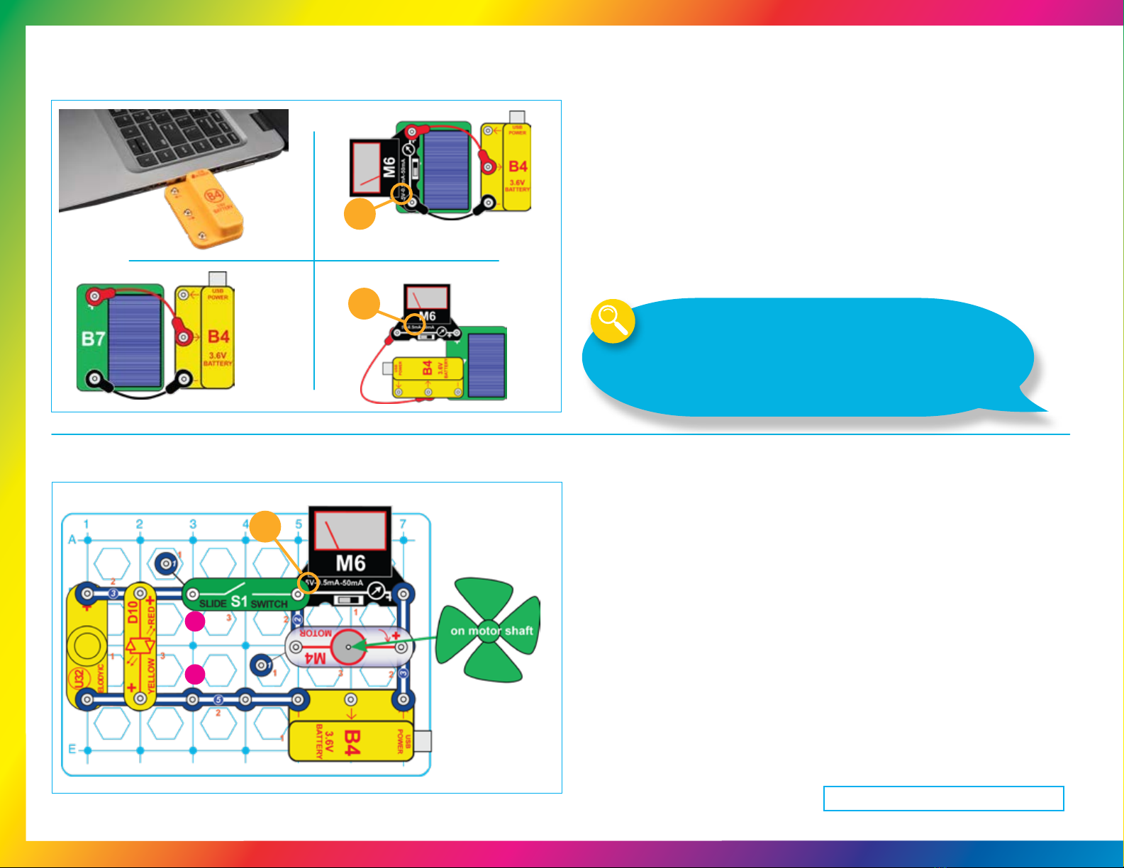
Project 3: Best Charging Circuits •Your Rechargeable Battery (B4) will need to be recharged often; it can
be charged with a USB connection or with solar light using any of these
circuits. The USB POWER light on B4 comes on when it is charging
through the USB.
•For solar charging, place the solar cell in sunlight or about 12 inches
from an incandescent light bulb of 60W or more. It takes a few hours to
charge the battery. LED, CFL, and uorescent lights do not work well
with solar cells. When measuring charge current, the current will often
be too high to measure on the 0.5mA setting but too low to measure on
the 50mA setting (you can use either). The current will get lower as the
battery approaches full charge.
You can’t hurt the battery by overcharging.
•Build the circuit and set the Meter (M6) to the 5V setting. Place the wind
fan on the Motor (M4). Turn on the Switch (S1). The LED (D10) lights, the
Melody IC (U32) makes a distorted sound, the fan spins, and the meter
shows the voltage across the motor. You may need to give the fan a push to
get it started. The voltage produced by the battery is split between the motor
and the LEDs and melody IC.
•Connect the red jumper wire across points labeled A & B. The LED and
melody IC turn off, the motor speeds up, and the meter shows a higher
voltage across the motor. With the jumper wire connected, the full voltage
from the battery is available at the motor because the LEDs and Melody IC
are bypassed.
Project 4: Moving Voltage
See project 3 if you need to recharge the battery (B4).
3
Although the battery is rated as 3.6V, it may charge to as high as 4.0V. If you are
monitoring the voltage using the meter, you may see the voltage quickly reach 3.6V,
but this does not mean that the battery is fully charged. When the battery is discharging
to power something, the voltage is nearly steady for a long while then drops off quickly.
The same thing occurs when it is charging. Recharging the battery will quickly reach
around 3.6V but it needs much more charging to avoid a quick drop-off when discharging.
Recharge the battery for several hours.
5V
USB Charging With Voltage measurement
Minimum parts: Measuring charge current:
0.5mA
5V
A
B

4
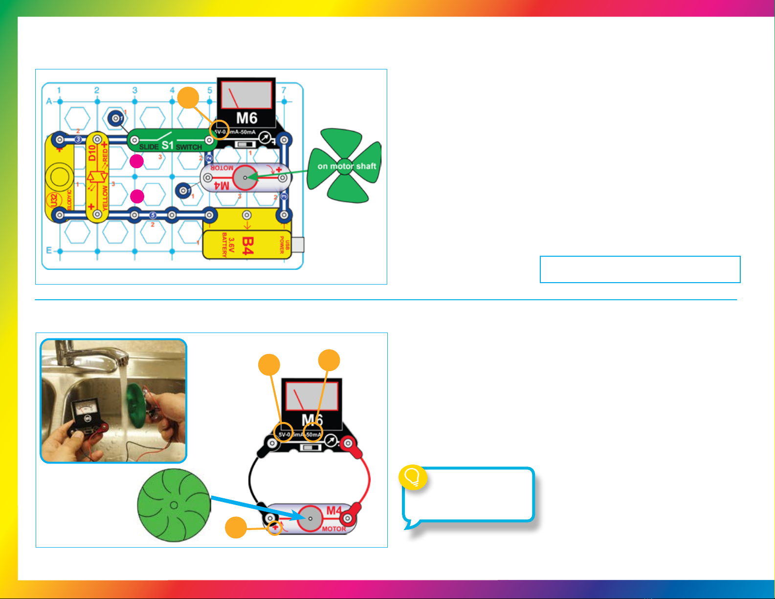
•Mount the Wind Fan on the
Motor (M4) and connect it to
the Meter (M6) using the red
and black jumper wires. Set
the meter to the 5V setting.
•Blow on the fan or place it in a
strong wind (either outside or
near an electric fan). You may
need to give the fan a push
to get it started. The meter
measures how much voltage
your “windmill” produces. See
how the voltage produced
changes with the angle to the
wind.
Project 7: Windmill
+
In the preceding circuit,
replace the Red/Yellow
LED (D10) with the Motor
(M4), in either direction)
and place the wind fan
on it. Now turn on the
switch and watch how the
voltage changes as the
solar cell runs the fan.
Depending on your light
source, the fan may need
a push to get started or
may not work at all.
•Place all the parts with a black 1 next to them on the green plastic base grid
rst, then parts marked with a 2, then the part marked with a 3. The red/yellow
LED (D10) may be connected in either direction.
•Place the circuit so the solar cell is in bright sunlight or close to an incandescent
light bulb. Set the Meter (M6) to the 5V setting.
•The meter is measuring the voltage produced by the solar cell. Adjust the
position of the solar cell to see how the voltage produced changes depending on
the angle to the light source and the brightness.
•Position the solar cell to make the highest voltage you can. Now turn on the
slide switch to run the red/yellow LED with the solar cell. Notice how the voltage
produced drops when the LED is connected.
•Compare the voltage and LED brightness when using different light sources
(sunlight, incandescent bulbs, LED bulbs, uorescent bulbs) to see which work
best with solar cells.
Project 5: Solar Power
Project 6: Solar Motor
Your solar cell makes electricity
from sunlight, but only a small
amount. In bright sunlight it produces a
voltage of about 7V, but this is reduced
when lots of current is owing. That is
why the voltage drops when you connect
the red/yellow LED.
The motor needs less electricity from
the solar cell as it speeds up, so the
solar cell voltage is higher as the
motor gets faster.
5V
5V
The windmill uses magnetism to
change the mechanical energy of the
spinning shaft into electricity. The voltage
it produces is usually lower than the solar
cell, but the current is higher.

5V
+
Project 9: Charge & Play
See project 3 if you need to recharge the battery (B4).
Project 8: Solar & Battery
50mA
See project 3 if you need to recharge the battery (B4).
5
•Build the circuit, set the Meter (M6) to the 50mA setting, and turn on the slide
Switch (S1). The Motor (M4) and fan spin, the Red/Yellow LED (D10) lights,
the Melody IC (U32) plays a tune, and the meter measures the current from
the Battery (B4).
•Place the Solar Cell (B7), which is connected using the Red & Black jumper
wires in direct sunlight or a few inches from an incandescent light bulb. If the
sunlight on the solar cell is very bright then the solar cell helps to power the
Motor, LED, and Melody IC, and the meter shows lower current because
less current is being drawn from the battery. Cover the solar cell with your
hand and see how much the current measured on the meter changes.
Part B: You can make the battery last longer if you turn off
some things. Remove the Melody IC, LED, or Motor from the
circuit, and see how much the current drops. Then remove
another. Some devices use more current than others, so it
helps most if you disconnect the highest current device - nd
out which one it is.
•Build the circuit shown here, set the Meter (M6) to the 5V setting, and
leave the Slide Switch (S1) off. The meter will measure about 3.6V if the
Battery (B4) is charged up.
•Place the Solar Cell (B7) in sunlight or a few inches from an
incandescent light bulb to charge the battery. The Red/Yellow LED (D10)
lights if the battery is being charged.
•Turn on the switch to play music on the Melody IC (U32). The voltage
measured may drop a little as the Melody IC slowly drains the battery.
Solar energy is free, abundant
and causes no pollution. However
it is difcult to harvest because even
low power solar cells are expensive.
Reducing how much energy we
use is just as important as nding
new sources of clean energy.

6
See project 3 if you need to recharge the battery (B4).
See project 3 if you need to recharge the battery (B4).
Project 10: Voltage Adder
Project 11: Wind Charger with Light
A
B
0.5mA
+
•Build the circuit shown. Set the Meter (M6) to the 0.5mA setting. Blow hard
on the fan or place it in a very strong wind (either outside or near an electric
fan). The “windmill” charges the Battery (B4) when the wind is blowing
hard, and the meter measures the charging current. Turn on the Switch
(S1) to turn on the LED (D10).
•Part B: Replace the Red/Yellow LED (D10) with the Melody IC
(U32, “+” on top). The circuit works the same except turning on the switch
makes sound. Here the Melody IC is run using wind power, by using the
battery for storage.
A problem with using wind to power a light is that the wind isn’t always blowing when
you need the light on. On the other hand, the wind is often blowing when you don’t need
the light on. So here you use the battery to store energy from the windmill when the wind
is blowing, and then run the LED when you need the light on. This way light is always
available from clean, free wind power.
+
0.5mA
1
•Set the meter (M6) to the 0.5mA or 50mA setting and turn on the Switch
(S1). Place the Solar Cell (B7) in bright sunlight or near an incandescent
lamp. If the light is bright enough, the Red/Yellow LED (D10) will be
bright and the Melody IC (U32) will play a tune. If the current is too high to
measure then change the meter to the 50mA scale.
•Now place a 3-snap wire across points A & B, to bypass the solar cell.
Now the LED is dimmer and the melody IC makes no sound or very
distorted sound,
When the solar cell is in the circuit
its voltage combines with the battery
voltage to make both the LED and
melody IC work.
•Build the circuit and set the Meter (M6) to the 5V setting. Place the wind fan
on the Motor (M4). Turn on the Switch (S1). The LED (D10) lights, the Melody
IC (U32) makes a distorted sound, the fan spins, and the meter shows the
voltage across the motor. You may need to give the fan a push to get it started.
The voltage produced by the battery is split between the motor and the LEDs
and Melody IC.
•Connect the Red Jumper Wire across points labeled A & B. The LED and
Melody IC turn off, the motor speeds up, and the meter shows a higher voltage
across the motor. With the jumper wire connected, the full voltage from the
battery is available at the motor because the LEDs and melody IC are bypassed.
5V
See project 3 if you need to recharge the battery (B4).
A
B
•Place the water wheel on the Motor (M4) and connect it to the Meter (M6),
as shown. Set the meter to the 5V or 50mA setting. Hold the motor under
a water faucet so the water wheel will “catch” the water as it falls. See how
much voltage and current you can produce.
•Using the water pressure from your faucet to make electricity using the motor
(used as a generator here) is just like using water pressure from a lake to run
an electric generator in a dam.
•Your parts might stop working if water gets inside them. Let them dry out and
they should be ne.
on motor shaft
50mA
5V
Project 12: Moving Voltage
Project 13: Changing Water Pressure to Electrical Pressure
+
7
Hoover Dam has a lake that is
500 feet deep on one side to
provide great pressure to turn the
generators that make our electricity.
8
•Remove the wind fan from the
motor shaft and replace it with
the Water Wheel. Watch how the
current is different with the larger
water wheel.
•The water wheel is heavier, so
it takes more current to spin it,
and doesn’t get as fast. Try laying
something on the water wheel to
give it even more weight.
See project 3 if you need to recharge the battery (B4).
•Build the circuit shown. Set the Meter (M6) to the 50mA setting and place the
wind fan on the Motor (M4). Turn on the slide switch (S1) and watch the current
on the meter as the motor speeds up.
•Do you know why the current drops as the fan speeds up?
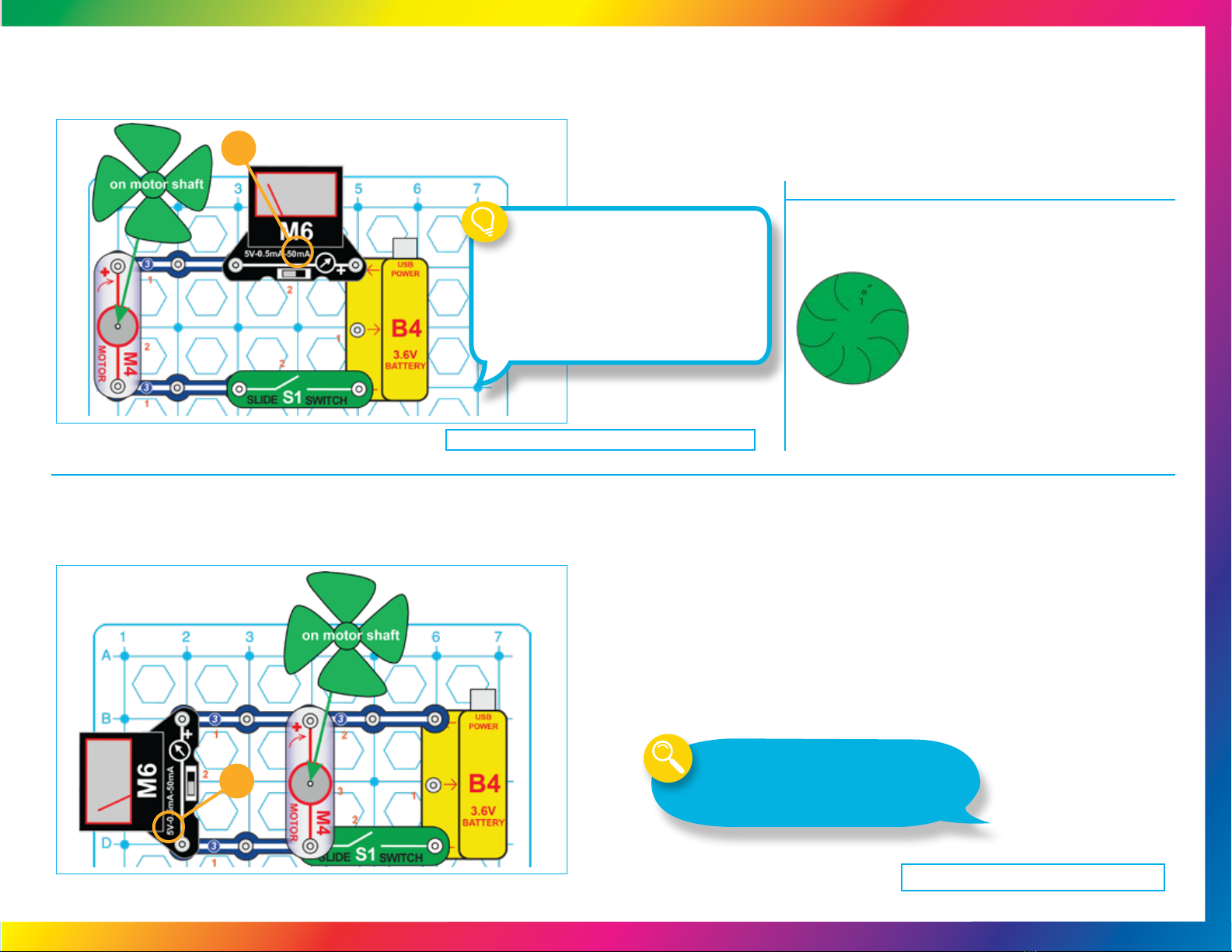
•Modify the preceding circuit into this one. Set the Meter (M6) to the 5V setting and
place the wind fan on the Motor (M4). Turn the Slide Switch (S1) on and off and
watch the voltage on the meter as the motor speeds up and slows down.
•Without pressing the switch, spin the fan clockwise with your nger and watch the
voltage. In the preceding project, the current dropped as the fan sped up - now you
see why. The spinning fan produces a voltage in the motor; this voltage opposes
the voltage from the battery, reducing the current as the motor speeds up.
•How will the voltage and current change if you replace the wind fan with the water
wheel? Try it.
5V
50mA
See project 3 if you need to recharge the battery (B4).
Project 14: Motor
Project 15: Water Wheel
Project 16: Motor Voltage
How does electricity turn the shaft in the motor?
The answer is magnetism. Electricity is closely
related to magnetism and an electric current owing
in a wire has a magnetic eld similar to that of a
very, very tiny magnet. Inside the motor is a coil of
wire with many loops. If a large electric current ows
through the loops, the magnetic effects become
concentrated enough to move the coil. The motor has
a magnet inside, so as the electricity moves the coil to
align it with the permanent magnet, the shaft spins.
Electricity is generated when you spin the motor shaft.
A coil of wire is on the shaft and as it spins past the
permanent magnet an electric current is created in the wire.

See project 3 if you need to recharge the battery (B4).
•This project combines several circuits to demonstrate what you can do with
Snap Circuits®Green Energy Lab. This circuit may be shown on your box
or manual cover.
•Assemble the circuits shown. Set the Meter (M6) to the 50mA setting. Turn
on the Slide Switch (S1). The Battery (B4) runs the Melody IC (U32).
•Place the solar cell (B7) in sunlight or near an incandescent light bulb to
charge the battery. The meter measures the changing current.
•Blow on the fan or spin it with your nger to light the Red/Yellow LED (D10).
The Motor (M4) acts as a generator, producing electricity to light the LED.
50mA
•Build the circuit shown. Set the Meter to the 5V setting, and keep the Slide
Switch (S1) off. Blow on the fan or place it in a strong wind (either outside or
near an electric fan). The meter measures how much voltage your “windmill”
produces. You may need to give the fan a push to get it started.
•Now turn on the Slide Switch (S1) to connect the Red/Yellow LED (D10) to
the Windmill. The voltage produced drops a little, but not as much as for the
solar cell circuits. Compare the brightness of the LED at different wind speeds.
•If the wind reverses direction then the meter will measure less than zero
voltage, and the Red/Yellow LED will light red. You can see this by spinning
the fan in both directions using your nger.
5V
+
Go to: to download projects 22 - 40
For Additional Projects:
Download projects 19-44,
more information about your parts
and how circuits work, and our Think
Green – Learn About Energy book.
Project 17: Windy Lights
Project 18: Box Cover Circuit
Go to:
www.elenco.com/scgrneng-manuals/
to download projects 19 - 44
9
There are many ways to
generate electricity, and many
more ways to use it!
10
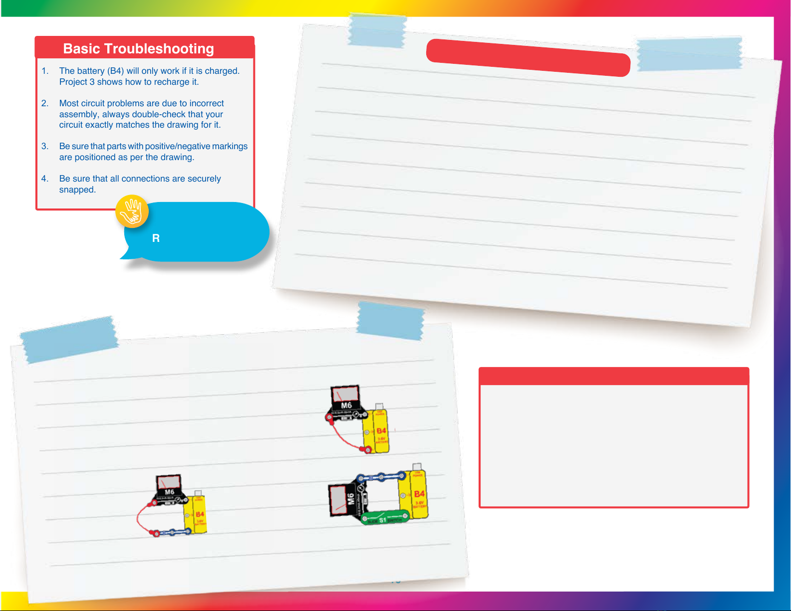
1. The battery (B4) will only work if it is charged.
Project 3 shows how to recharge it.
2. Most circuit problems are due to incorrect
assembly, always double-check that your
circuit exactly matches the drawing for it.
3. Be sure that parts with positive/negative markings
are positioned as per the drawing.
4. Be sure that all connections are securely
snapped.
Basic Troubleshooting
Advanced Troubleshooting
Elenco
®
is not responsible for parts damaged due to incorrect wiring.
If you suspect you have damaged parts, you can follow this procedure to
systematically determine which ones need replacing:
● Plug B4 into a powered USB port; the “USB POWER” light on B4 should
come on, indicating that it is being charged by the USB. Next, set the meter
to the 5V setting and touch it across B4; the meter pointer should move. If the
meter measures 3V or less then recharge B4 using project 3. If B4 cannot be
recharged then it is damaged. Set the meter to the 0.5mA and 50mA scales;
the reading should be maximum. Touch the D10 directly across B4, it should
light red or yellow (depending on which way you oriented it). Touch the motor
across the snaps on B4, it should spin.
● If the meter, LED, and motor all do not work then B4 is damaged; if one of
them did not work then that device is damaged.
● You should also conrm that B4 can be charged using the solar cell (B7).
Conrm that B7 works, then use the “Measuring Charge Current” circuit of
project 3. If the meter measures any current then B4 is ne.
1. To Test:
Battery (B4)
Meter (M6)
Red/Yellow LED (D10)
Motor (M4):
ADULT
SUPERVISION
RECOMMENDED
5. Slide switch (S1): Set
the meter to the 5V setting
and build this circuit. If the
meter pointer does not
move when you turn on
the switch, the switch is
damaged.
4. Snap wires:Set the
meter to the 5V setting
and use this circuit to
test each snap wire,
one at a time. The
snap does not move.
3. Red & Black Jumper wires: Set the meter to the 5V setting and use this
circuit to test each jumper wire. The jumper wire is damaged if the meter
pointer does not move.
6. Melody IC (U32):
Touch the melody IC directly across the snaps on the battery (B4), U32 “+” to battery “←”.
You should hear a tune. If the sound is distorted then recharge the battery.
2. Solar cell (B7): Place the meter directly across the solar cell and set it to the 5V setting. Place the solar cell
in sunlight or near a bright light source (incandescent light bulbs are best); the meter pointer should move.
Be sure you used a bright light source and removed any protective plastic wrap covering the solar cell.
IMPORTANT:
If any parts are missing or damaged,
DO NOT RETURN TO RETAILER.
Go to elenco.com/replacement-parts or e-mail us at
Note: A complete parts list is on page 2 in this manual.
If you have any problems, contact: ELENCO®
ELECTRONICS, LLC
150 Carpenter Ave. Wheeling, IL 60090 | (800) 533-2441
e-mail: [email protected] z

If you have any problems, contact: ELENCO® ELECTRONICS, LLC
150 Carpenter Ave. Wheeling, IL 60090 | (800) 533-2441 | e-mail: [email protected] | elenco.com
Base Grid (7.7” x 5.5”) overlays some parts.
Snap Circuits®Green Energy Lab Parts Layout
IMPORTANT:
If any parts are missing or damaged, DO NOT RETURN TO RETAILER. Go to elenco.com/replacement-parts or e-mail us at [email protected].
Note: A complete parts list is on page 2 in this manual.
Copyright © 2023 ELENCO®Electronics, LLC. All Rights Reserved.
Conforms to all applicable U.S. government requirements and CAN ICES-3 (B)/NMB-3 (B).
Model: SC-GRNENKT | Part #753342
Table of contents
Other SNAP CIRCUITS Science Education Product manuals


