Zantiks MWP User manual

The following instructions are for MWP
units purchased before March 2021
Zantiks MWP kit:
1. Integrated unit (approx. 270mm H; 220mm D; 160mm W) with:
• Zanscript (Zantiks proprietary scripting software)
• Built-in features / stimuli
• overhead 'house lights'
• screen on the MWP_sc
• vibration motor on the MWP_vb
• Camera
• Computer
2. A 12V power cable
3. Zantiks router, power cable, and Ethernet cable
• Zantiks router is supplied with the first unit, this is typically a TP Link
router (previously Cisco) with 4 LAN ports and 1 WAN port.
Subsequent units can be networked to this router, using a network
switch if necessary.
4. Stand to hold a multi-well plate or Petri dish
• The type of stand will vary depending on the unit. MWP_vb with come
with a diffuser stand, MWP_sc with come with a clear stand.
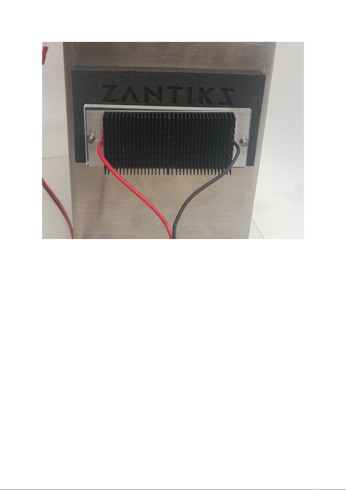
5. A standard temperature control system is included with all units. The peltier
temperature control system is offered as an optional add on if required.
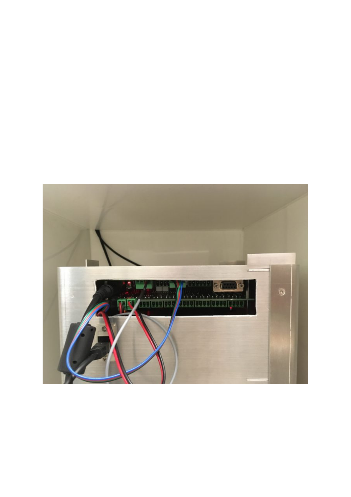
Assembling the motor plate
If you have purchased the MWP_vb unit you need to insert the motor plate into the
unit before using it. The motor plate is delivered detached in order to prevent
breakage during transit.
The link below shows how to open the front section of the MWP_vb unit so that the
motor plate can be inserted and attached. You will need a T10 Torx driver, or
similar, not an allen key to do this (this tool should be included with your unit).
Please note the MWP_sc unit does not have a built-in motor, so these assembly
instructions are not valid for this version.
https://www.youtube.com/watch?v=413nz3j7dKQ

Setting up the MWP
The video below demonstrates how to set up the MWP unit including the layout of
the cables in the socket panel, and how to insert a well-plate into the chamber
with or without a stand.
https://www.youtube.com/watch?v=7mjtl-jJOZ8
1. Place the MWP unit on a stable surface close to a power socket and away
from disturbances.
2. Insert the 12V power supply cable into the top left side socket of the MWP
and plug it into the mains socket.
3. Connect the ethernet cable at the side of the MWP unit, just below the 12V
power cable, and plug this into any of the 4 slots available in the LAN
section of the router.
Side socket of MWP unit showing where to insert the green connector plugs and cables.
Bottom left the Ethernet cable plugs in; directly above it is the 12V power supply cable.
On the bottom board are two 2-way green, connector plugs. On the top green connection
board are the 4-way connector plug for the thermistor (left) and the 4-wire connector plug
for the overhead lights (right).

4. Turn on the router and the mains power to the Zantiks unit. Wait a few
minutes for the MWP unit to power on. When using the MWP version with a
screen, text will scroll across the screen before displaying the IP address of
the unit (which begins with the same 7 digits 192.168.1.). When using the
MWP_vb, your IP address is included on your delivery note. If you have only
one Zantiks unit, the IP address will be 192.168.1.101. The IP address is
used to identify the unit on the Zantiks Control Console.
5. Using any browser-enabled device:
• go to your device’s network settings and connect to the wifi network
“Zantiks”
• type in the network password, which is initially provided as:
behaviour, simply
• go to the address bar of the web browser and type in the IP address
for your Zantiks unit
6. Your web browser should now display the Zantiks Control Console page.
Temperature control options for the
MWP
For information on temperature control options and their set up. Please refer back to the
MWP manual. These have not changed between models.
Assembling the Light Stand
The light stand can incorporate a diffusing stand, and so replaces the standard
diffusing stand that is supplied with the MWP_vb unit. The main components
include:
1. Light stand with incorporated diffusing stand
2. LED holder (with your choice of wavelength lights)
3. Control circuit to plug directly into the MWP unit
4. Foam door (with hole for light plate)

The main components of the light stand.
The system plugs directly into the MWP, and does not require an additional power
supply.
Control of the system is from the included Zanscript programming language, and
incorporates control of both the brightness of the light and the duration of the
stimulus.
The brightness of the light is controlled by the voltage set on output4. This is the
7th connector on the 8-way output located at CN5 of the lower board (see
picture).
The light being on or off is controlled by the relay output from CN4, which is the
second of the 3 way connectors on the lower board from the left (see picture).

Side socket of MWP unit demonstrating how the wires for the light stand should be
connected in CN4 and CN5 of the lower board
The LED holder is then connected to the control circuitry with the push
connectors.
Push plugs connecting LED holder to the control circuit

Connection of the LED holder to the MWP unit via the control circuit
The LED holder can be attached to the light plate. This can then be inserted into
the MWP unit with the foam door to prevent any excess light entering or exiting
the unit (see images below).

LED holder attached to light stand with green LEDs

Light stand with LED holder inserted into MWP unit with foam door to prevent light
escaping
We are using a third party LED driver device which allows us to control the on/off
and brightness of the LEDs from the ZANTIKS script and electronics. This allows the
system to be fully integrated into the Zantiks experiments.
The LED driver is permanently powered from the 3-way connector plugged in as in
the previous photo (CN4). CN4 each provides permanent 12V power, a 12V power
source switched by relays controlled from Zanscript, and a ground connection. CN4
has power applied by default, and when power is provided here the plate will not
be lit. When power is not applied then the LED will light as controlled by the
voltage out from the 4th output of CN5. High voltages (10000 mv) keep the stand
unlit, and low voltages (anything below about 4000mv) will have the stand at full
power.
Table of contents