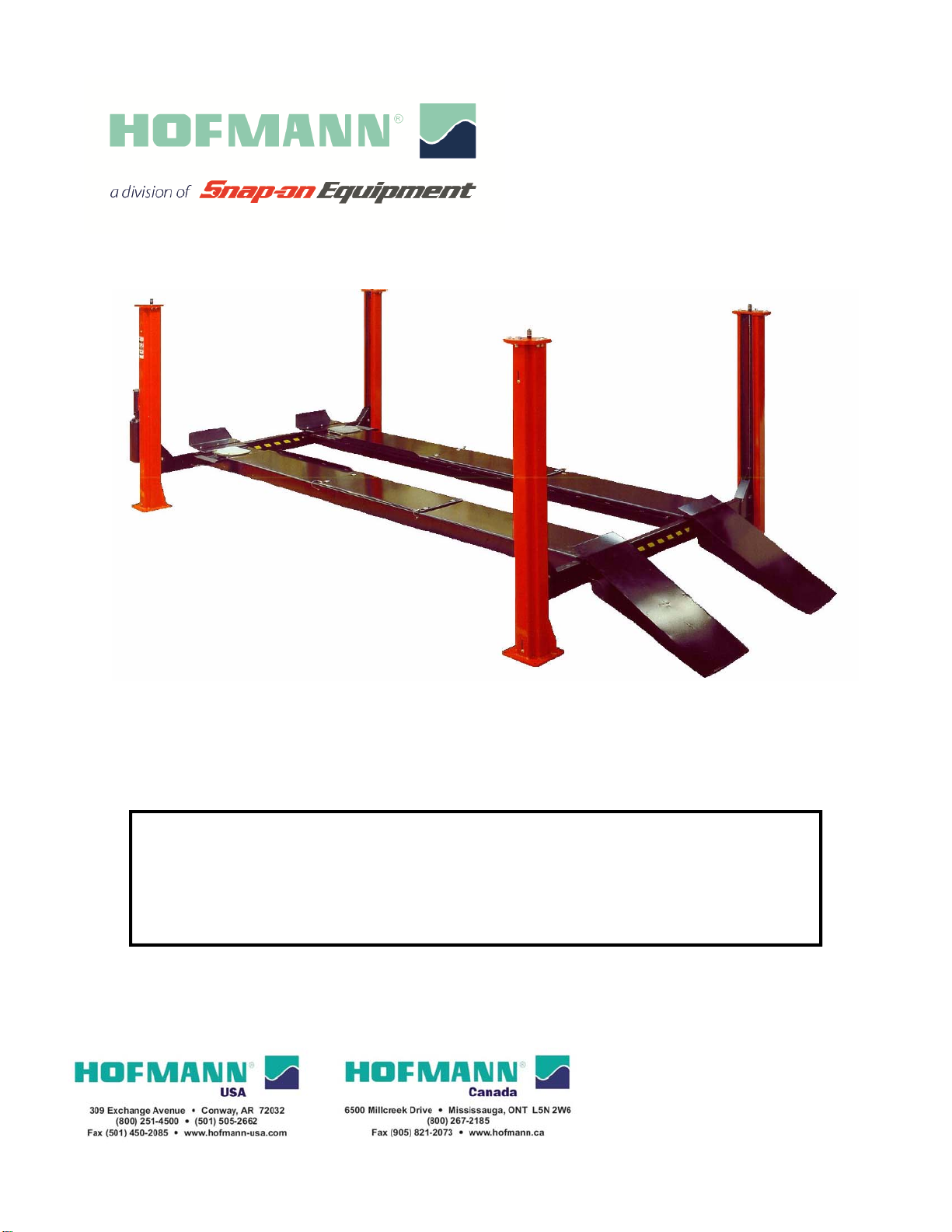
Snap-on Equipment Hofmann ALIGNMENT FPA18210 User manual
INSTALLATION
d OPERATION
INSTALLATION
d OPERATION
an
d
OPERATION
MANUAL
an
d
OPERATION
MANUAL
READ THIS INSTRUCTION MANUAL THOROUGHLY BEFORE
INSTALLING OPERATING SERVICING OR MAINTAINING THE
INSTALLING
,
OPERATING
,
SERVICING
OR
MAINTAINING
THE
LIFT. SAVE THIS MANUAL.
4-POST 18,000LBS
MODEL: ALIGNMENT FPA18210
SERVICE FPF18210
DEC 2016 REV.- 6-3347

2 of 75
TABLE OF CONTENTS PAGE
1.0OWNER / EMPLOYER OBLIGATIONS......................................................4
2.0IMPORTANT SAFETY INSTRUCTIONS....................................................5
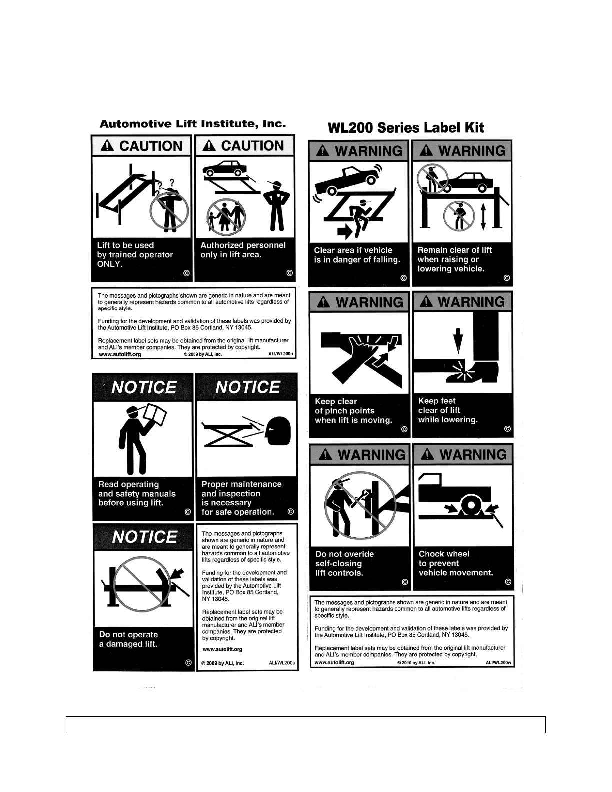
2.1Safety Warning Labels .........................................................................8
3.0GENERAL SPECIFICATION......................................................................9
3.1Service & Alignment Wheelbase Specification...................................10
4.0INSTALLATION REQUIREMENTS & TOOLS..........................................10
4.1Foundation .........................................................................................10
4.2Tools ..................................................................................................10
5.0CONTENTS..............................................................................................11
6.0BAY LAYOUT...........................................................................................12
6.1Typical Bay Layout.............................................................................13
6.2Chalk Line Layout...............................................................................14
6.3Identification of Components..............................................................16
7.0INSTALLATION INSTRUCTIONS............................................................17
7.1Assembly of Cables to Left Side Deck ...............................................17
7.2Assembly of Front & Rear Crossmember...........................................22
7.3Tower Assembly.................................................................................24
7.4Installation of towers...........................................................................25
7.5cable to tower installation...................................................................26
7.6Power Pack Installation......................................................................27
7.7Hydraulic Installation ..........................................................................28
7.8Air Installations...................................................................................29
7.9Electrical Connections........................................................................30
7.10Filter/Regulator/Lubricator Commisionning ........................................31
7.11Deck Leveling Procedure ...................................................................33
7.11.1Leveling Lift to Floor..................................................33
7.11.2Deck Leveling Procedure..........................................33
7.12Leveling on Safety Ladders................................................................34
7.13Anchor Installation..............................................................................35
7.14Accessory Installation.........................................................................37
7.15Final Check Of Assembled Lift...........................................................38
8.0OPERATING INSTRUCTIONS.................................................................39
8.1Operation Test With Vehicle...............................................................41
9.0SAFETY AND OPERATING INSTRUCTIONS.........................................41
10.0RECOMMENDED INSPECTION AND MAINTENANCE ..........................42
10.1Lubrication Specifications...................................................................42
10.2Maintenance Records ........................................................................44
10.3Wire Ropes.........................................................................................45
10.3.1Wire Rope Conditions Guide.....................................45
10.3.2Wire Rope Replacement Criteria...............................46

3 of 75
10.3.3Wire Rope Inspection................................................46
10.3.4Wire Rope Lubrication...............................................46
10.3.5Wire Rope Adjustment..............................................46
10.3.6Inspect Cable Flange................................................47
10.4Fasteners ...........................................................................................47
10.5Sheaves & Pins..................................................................................47
10.5.1Visual Inspection of Sheaves....................................47
10.5.2Measure Sheave Wear .............................................47
10.5.3Sheave Pins..............................................................48
10.6Mechanical Safety Latch (Dog) ..........................................................48
10.7Auxiliary Safety Mechanism ...............................................................48
10.8AirCylinders, Air Lines, Valves and Fittings........................................48
10.8.1General Checks ........................................................48
10.8.2Air Lubricator Oil Level..............................................49
10.9Hydraulic PowErpack and Hose.........................................................49
10.10Hydraulic Cylinder ..............................................................................49
10.11Runways.............................................................................................50
10.11.1Check Runways........................................................50
10.11.2Inspect Jackbeam Tracks .........................................50
10.12Columns.............................................................................................50
10.12.1Check Columns.........................................................50
10.12.2Check Column Anchors ............................................50
10.13Approach Ramps, Chocks, Front Wheel Stops..................................50
10.14Front and Rear Turn/Slip Plates.........................................................51
10.14.1Visual Inspection.......................................................51
10.14.2Clean Rear Slip Plates and Front Turn Tables..........51
10.14.3Maintenance of Rear Steer Plates ............................51
10.14.4Maintenance of Rear Steer Plates - If Equipped with Plastic
Bearing Cage.................................................................................51
10.14.5Anti-Skid Coating on Rear Steer Plates....................51
10.15Rolling Air Jacks.................................................................................52
10.16Entire Lift............................................................................................52
11.0LOCK OUT AND TAG OUT INSTRUCTIONS..........................................52
11.1Isolation and Verification Procedure:..................................................54
11.2Emergency Operation ........................................................................55
12.0PARTS LIST.............................................................................................57
12.1Lift Assembly......................................................................................57
12.2Parts List – Lift Assembly...................................................................58
12.3Tower Assembly.................................................................................59
12.4Parts List – Power Tower Assembly...................................................60
12.5Deck Assembly (Left Side).................................................................61
12.6Parts List – Deck Assembly (Left Side)..............................................62
12.7Crossmember Assembly ....................................................................63
12.8Parts List – Crossmember Assembly .................................................64
12.9Cylinder Assembly..............................................................................65
12.10Parts List – Cylinder Assembly...........................................................66
12.11Hydraulic And Air Kit ..........................................................................67
12.12Parts List – Hydraulic And Air Kit........................................................68
12.13Filter / Regulator / Lubricator Assembly .............................................69

4 of 75
12.14Cable Routing.....................................................................................70
12.15Parts List – Cable Routing..................................................................71
12.16Power Pack Assembly........................................................................72
12.17Parts List – Power Pack .....................................................................73
13.0AVAILABLE ACCESSORIES ...................................................................75
1.0 OWNER / EMPLOYER OBLIGATIONS
1. The Owner/Employer shall ensure that lift operators are qualified and that they
are trained in the safe use and operation of the lift using the manufacturer’s
operating instructions; ALI/SM 93-1, ALI Lifting it Right safety manual; ALI/ST-
90 ALI Safety Tips card; ANSI/ALI ALOIM-2008, American National Standard
for Automotive Lifts - Safety Requirements for Operation, Inspection and
Maintenance; ALI/WL Series, ALI Uniform Warning Label Decals/Placards;
and in the case of frame engaging lifts, ALI/LP-GUIDE, Vehicle Lifting
Points/Quick Reference Guide for Frame Engaging Lifts.
2. The Owner/Employer shall establish procedures to periodically inspect the lift in
accordance with the lift manufacturer’s instructions or ANSI/ALI ALOIM-2008,
American National Standard for Automotive Lifts - Safety Requirements for
Operation, Inspection and Maintenance; and the Employer shall ensure that
the lift inspectors are qualified and that they are adequately trained in the
inspection of the lift.
3. The Owner/Employer shall establish procedures to periodically maintain the lift in
accordance with the lift manufacturer’s instructions or ANSI/ALI ALOIM-2008,
American National Standard for Automotive Lifts - Safety Requirements for
Operation, Inspection and Maintenance; and the Employer shall ensure that
the lift maintenance personnel are qualified and that they are adequately trained
in the maintenance of the lift.
4. The Owner/Employer shall maintain the periodic inspection and maintenance
records recommended by the lift manufacturer’s instructions or ANSI/ALI ALOIM-
2008, American National Standard for Automotive Lifts - Safety
Requirements for Operation, Inspection and Maintenance.
5. The Owner/Employer shall display the lift manufacturer’s operating instructions;
ALI/SM 93-1, ALI Lifting it Right safety manual; ALI/ST-90 ALI Safety Tips
card; ANSI/ALI ALOIM-2008, American National Standard for Automotive
Lifts - Safety Requirements for Operation, Inspection and Maintenance;
ALI/WL Series, ALI Uniform Warning Label Decals/Placards; and in the case
of frame engaging lifts, ALI/LP-GUIDE, Vehicle Lifting Points/Quick Reference
Guide for Frame Engaging Lifts in a conspicuous location in the lift area
convenient to the operator.
6. The Owner/Operator shall provide necessary lockout/tagout means for energy
sources per ANSI Z244.1-1982 (R1993), Safety Requirements for the

5 of 75
Lockout/Tagout of Energy Sources, before beginning any lift repairs and
maintenance.
7. The Owner/Employer shall not modify the lift in any manner without the prior
written consent of the manufacturer.
DO NOT ATTEMPT TO OPERATE THIS LIFT IF ANY PART
IS NOT WORKING PROPERLY OR YOU HAVE NOT READ THE COMPLETE
OPERATING INSTRUCTION MANUAL.
2.0 IMPORTANT SAFETY INSTRUCTIONS
1. When using this lift, basic safety precautions should always be followed,
including the following:
2. Read all instructions in this manual and on the lift thoroughly before installing,
operating, servicing or maintaining the lift.
3. Care must be taken as burns can occur from touching hot parts.
4. Do not operate equipment with a damaged cord or if the equipment has been
dropped or damaged – until it has been examined by a qualified service person.
5. Do not let a cord hang over the edge of the table, bench, or counter or come in
contact with hot manifolds or moving fan blades.
6. If an extension cord is necessary, a cord with a current rating equal to or more
than that of the equipment should be used. Cords rated for less current than the
equipment may overheat. Care should be taken to arrange the cord so that it will
not be tripped over or pulled.
7. Always unplug equipment from electrical outlet when not in use. Never use the
cord to pull the plug from the outlet. Grasp plug and pull to disconnect.
8. Let equipment cool completely before putting away. Loop cord loosely around
equipment when storing.
9. To reduce the risk of fire, do not operate equipment in the vicinity of open
containers of flammable liquids (gasoline).
10.Adequate ventilation should be provided when working on operating internal
combustion engines.
11.Keep hair, loose clothing, fingers, and all parts of body away from moving parts.
12.To reduce the risk of electric shock, do not use on wet surfaces or expose to rain.

6 of 75
13.Use only as described in this manual. Use only manufacturer’s recommended
attachments.
14.ALWAYS PERSONAL PERTECTIVE EQUIPMENT. Everyday eyeglasses only
have impact resistant lenses, they are not safety glasses.
15.Inspect lift daily. Do not operate if it malfunctions or problems have been
encountered.
16.Never attempt to overload the lift. The manufacturer’s rated capacity is shown on
the identification label on the power side column. Do not override the operating
controls or the warranty will be void.
17.Before driving vehicle between the towers, position the arms to the drive-through
position to ensure unobstructed clearance. Do not hit or run over arms as this
could damage the lift and/or vehicle.
18.Only trained and authorized personnel should operate the lift. Do not allow
customers or bystanders to operate the lift or be in the lift area.
19.Position the lift support pads to contact the vehicle manufacturers recommended
lifting points. Raise the lift until the pads contact the vehicle. Check pads for
secure contact with the vehicle. Check all arm restraints and insure they are
properly engaged. Raise the lift to the desired working height.
20.Some pickup trucks may require an optional truck adapter to clear running
boards or other accessories.
21.NOTE: Always use all 4 arms to raise and support vehicle.
22.Caution! Never work under the lift unless the mechanical safety locks are
engaged.
23.Note that the removal or installation of some vehicle parts may cause a critical
load shift in the center of gravity and may cause the vehicle to become unstable.
Refer to the vehicle manufacturer’s service manual for recommended
procedures.
24.Always keep the lift area free of obstruction and debris. Grease and oil spills
should always be cleaned up immediately.
25.Never raise vehicle with passengers inside.
26.Before lowering check area for any obstructions.
27.Before removing the vehicle from the lift area, position the arms to the drive-thru
position to prevent damage to the lift and /or vehicle.
28.Do not remove hydraulic fittings while under pressure.
7 of 75
For additional safety instructions regarding lifting, lift types, warning labels, preparing to
lift, vehicle spotting, vehicle lifting, maintaining load stability, emergency procedures,
vehicle lowering, lift limitations, lift maintenance, good shop practices, installation,
operator training and owner/employer responsibilities, please refer to “Lifting It Right”
(ALI/SM) and “Safety Tips” (ALI/ST) and vehicle lift points for service garage
lifting SAE J2184.
For additional instruction on general requirements for lift operation, please refer to
“Automotive Lift-Safety Requirements For Operation, Inspection and
Maintenance” (ANSI/ALI ALOIM).
Installation shall be performed in accordance with ANSO/ALI ALIS, Safety
Requirements for Installation and Service of Automotive Lifts.
ATTENTION! This lift is intended for indoor installation only. It is
prohibited to install this product outdoors. Operating
environment temperature range should be 41 – 104 °F (5 – 40 °C).
Failure to adhere will result in decertification, loss of warranty,
and possible damage to the equipment.
8 of 75
SAVE THESE INSTRUCTIONS
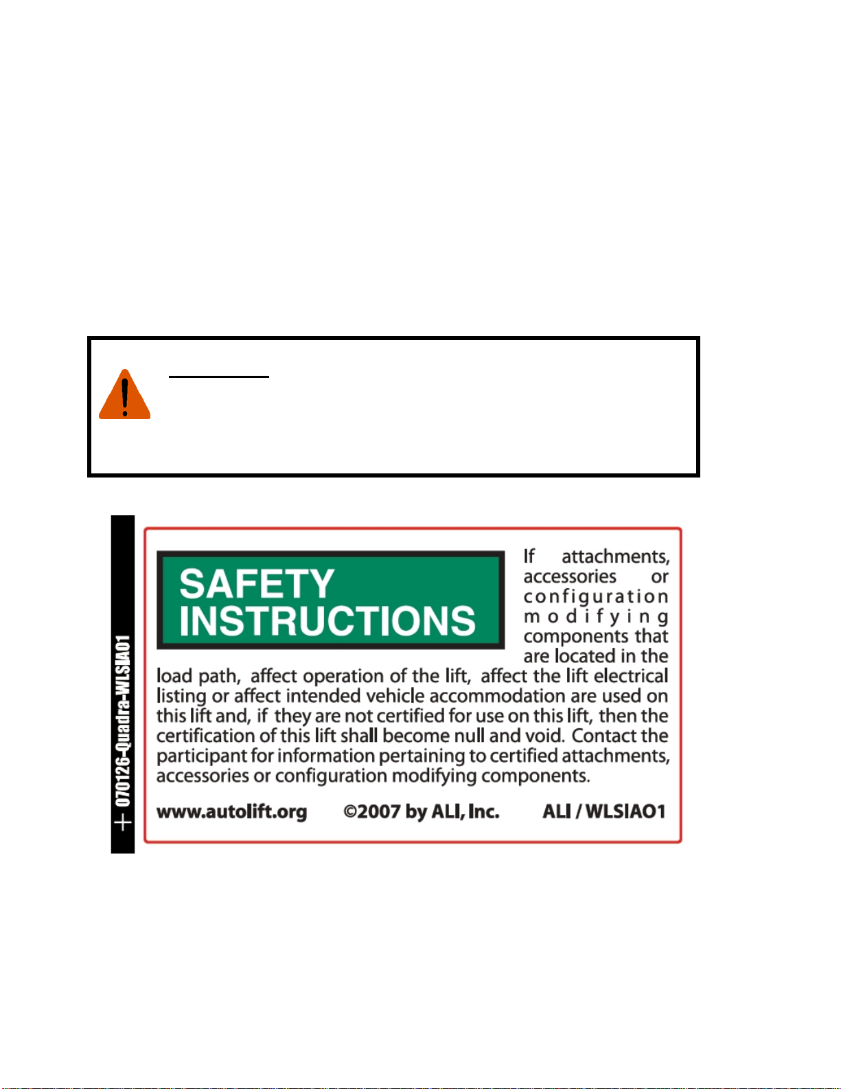
2.1 SAFETY WARNING LABELS
SAVE THESE INSTRUCTIONS

9 of 75
3.0 GENERAL SPECIFICATION
Figure 1 - General Specifications
Maximum Capacity 18,000 lb 8165 kg
Maximum Wheelbase – General Service 220” 5588 mm
Maximum Wheelbase – 2-Wheel
Alignment 203” 5156 mm
Maximum Wheelbase – 4-Wheel
Alignment 144” 3658 mm
Minimum Wheelbase – 4-Wheel Alignment 86” 2184 mm
Overall Length 303-3/8” 7706 mm
Overall Width 152-1/8" 3864 mm
Lowered Runway Height 9-1/2" 241 mm
Maximum Lifting Height (to runway
surface) 72” 1829 mm
Rise Time 70 Seconds
Ramp approach angle (no shims) 10°
Power Requirements 230VAC, 1PH., 20A, 60 Hz
Shipping Weight 5465 lb 2484 kg
Maximum Operating Pressure (Full Load): 2650 psi 183 bar
Air Supply Requirements: 90 - 120 psi 6 - 8 bar

10 of 75
3.1 SERVICE & ALIGNMENT WHEELBASE SPECIFICATION
4.0 INSTALLATION REQUIREMENTS & TOOLS
4.1 FOUNDATION
It is the user’s responsibility to provide a satisfactory installation area for the lift. Lifts
should only be installed on level concrete floors with a minimum thickness of six inches
(6") or 152 mm. Concrete must have a minimum strength of 4000 psi or 28 MPa and
should be aged thirty (30) days prior to installation. Please consult with an architect,
contractor or engineer if doubt exists as to the strength and feasibility of the floor to
enable proper lift installation and operation.
A qualified person should be consulted to address seismic loads and other local or state
requirements.
It is the user’s responsibility to provide all wiring for electrical hook-up prior to
installation and to insure that the electrical installation conforms to local building codes.
Where required, it is the user’s responsibility to provide an electrical isolation switch
located in close proximity to the lift that will enable emergency stop capability and
isolate electrical power from the lift for any servicing requirements.
4.2 TOOLS
ROTARY HAMMER DRILL
3/4” CONCRETE DRILL BIT
SELF LEVELING LASER OR 4’ LEVEL
HAMMER (for anchor installation)
PRY BAR (for shim installation)
CHALK LINE (lift location)
TAPE MEASURE
ELECTRICAL TAPE

11 of 75
STEP LADDER (adjusting cables and/or safety ladder in posts)
SIDE CUTTERS (for cutting shipping straps)
(8) JACK STANDS (set up)
STANDARD SOCKETS AND WRENCHES
ALLAN KEY SET
SCREWDRIVER SET
FLOOR JACK OR ENGINE HOIST
BOX CUTTER / SNIPS (to remove packaging)
RUBBER OR PLASTIC MALLET
5.0 CONTENTS
The lift is packaged to protect it from any damage that may occur during shipping. The
two deck assemblies and crossmembers are packaged together with the accessory
boxes strapped to them.
Main Structural Components:
1 - Left Side Deck Assembly (complete with hydraulic cylinder, sheaves and cables)
1 - Right Side Deck Assembly
1 - Front Crossmember Assembly (with air cylinder release locks and sheaves)
1 - Rear Crossmember Assembly (with air cylinder release locks and sheaves)
Accessory Box Components
Box 1 Contents:
1 - Power Post (with safety ladder)
3 - Post (with safety ladder)
Box 2 Contents:
1 - Hardware Kit (with separate packaging list)
2 - Ramp pin
2 - Front Wheel Stop
4 - Sheave Cover
2 - Approach Ramp
1 - Coupler, ¼”NPT
2 - Recoil Hose
1 - Power Unit 220v/1Ph/3hp
10ft - 1/4” DIA. Polytube
10ft - 3/8” DIA. Polytube
1 - Hose Guard
1 - Hydraulic Hose Assembly (16ft. lg.)
2 - Cable Tie
1 - Air Valve & Filter Assembly
1 - Flow Control
1 - Installation & Operation Manual
1 - Lift it Right Manual “ALI”
1 - Lift it Right Safety Tips

12 of 75
1 - “ALI” Standards
1 - “ALI” Quick Reference Guide
8 - Glide Bearing
4 - Lifting cables
6.0 BAY LAYOUT
PLEASE TAKE THE TIME TO READ THESE INSTRUCTIONS COMPLETELY.
A QUICK CHECK OF THE CONTENTS OF THE ACCESSORY BOX WOULD
ALSO DECREASE THE INSTALLATION TIME.
1. Gather the tools and materials required for the installation.
2. Select the location best suited for your lift.
NOTE: In determining lift area check for the following:
Ease of driving a vehicle on and off the lift.
Overhead obstructions, low ceiling height, overhead doors, overhead heaters etc.
Floor obstructions, uneven floor in lift area, floor drains, work benches, electrical
wiring in floor, etc.
Anchor locations must be a minimum of 6" from any cracks
An outline matching the dimensions shown in Figure 2 will need to be marked on
the floor. Refer to Figure 3 for outline dimensions. Refer to General Lift
Specifications for overall lift dimensions.
Recommended minimum clearance around the lift is three (3) feet. Ensure
clearance conforms to local building and fire codes.
Recommended overhead clearance is a minimum twelve (12) foot ceiling
providing 6 feet for the maximum lift height and 6 feet for the supported vehicle.
For vehicles taller than 6 feet it is recommended that the user provides additional
overhead clearance or a shut off mechanism to stop the lift from raising the
vehicle too high.
DO NOT install the lift on asphalt or other unstable surfaces. Lift
columns are supported only by anchors in floor.
INSTALLER: PLEASE RETURN THIS BOOKLET TO LIFT OWNER/OPERATOR
AFTER COMPLETING INSTALLATION
13 of 75
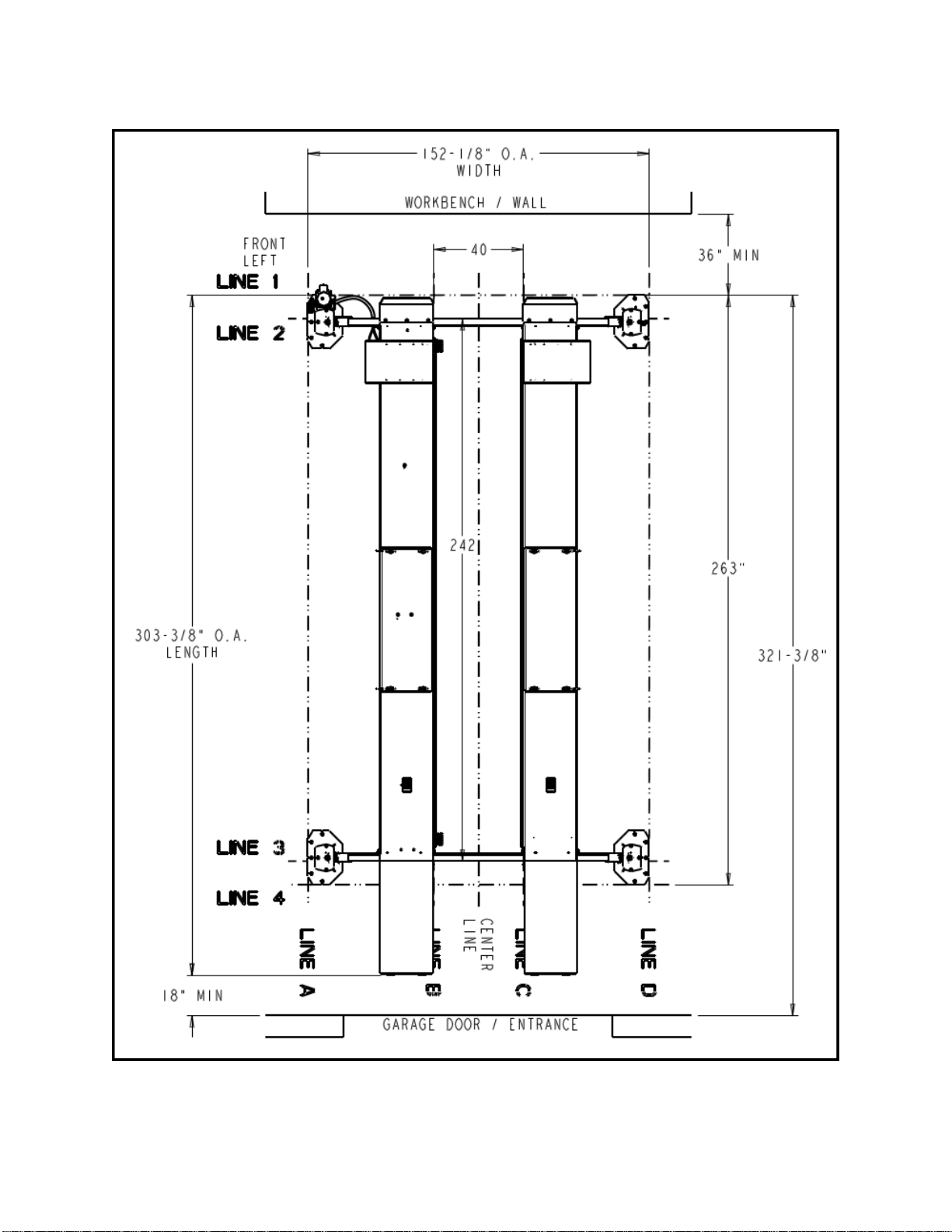
6.1 TYPICAL BAY LAYOUT
Figure 2 - Typical Bay Layout

14 of 75
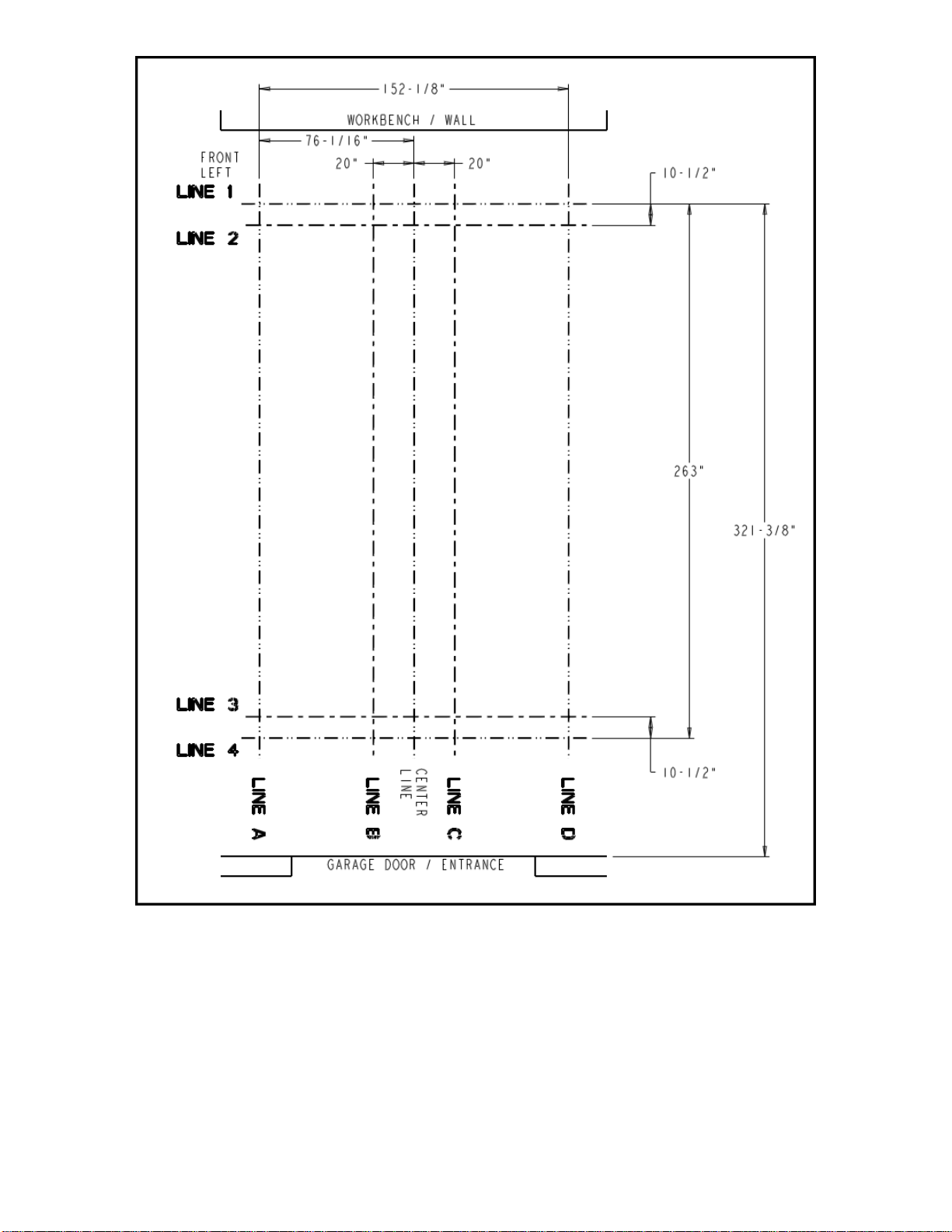
6.2 CHALK LINE LAYOUT
None of the anchors shall be closer than 4-3/4" to any edge of a
concrete slab, expansion joint or crack in the garage floor. Review
position of front towers, base plates and anchors, and relocate lines "1", "A", "D" if
needed.
1. Refer to Figure 2 & 3. Make a chalk line parallel to the doorway at least 321-
3/8” in from the doorway. This will be the location for the front face of the tower
baseplate. Call this line "1".
2. Determine the center of the doorway and bay. Make a centerline to intersect with
line "1".
3. Make a chalk line parallel to line “1”, 263” back toward the door. Call this line “4”.
4. Make a chalk like parallel to line "1", 10-1/2" towards door. Call this line "2".
5. Make a chalk like parallel to line "4", 10-1/2" towards front. Call this line "3".
Lines "2" and "3" will be the lines that the front and rear of the runways
align to.
6. Make a chalk lines parallel to the center line 76-1/16” to the left side and
intersecting line “1” and line ”4”. Call this line “A”.
7. Make a chalk line parallel to line "A" 152-1/8" to the right, intersecting lines "1"
and 4". Call this line "D".
Lines "A" & "D" and "1" & "2" will be the lines that the outside edge of the
tower baseplates align to.
8. Make two chalk lines spaced 20" to the left and right side of the centerline
intersecting line “1” and line ”4”. Call these lines, line “B” & "C".
Lines "B" & "C" will be the lines that the inside edge of the runways align
to.
15 of 75
Fi
g
ure 3 - Chalk line la
y
out

16 of 75
6.3 IDENTIFICATION OF COMPONENTS
1. Identify and unpack major lift components (Towers, Crossmembers & Runways)
and place them where they belong according Figure 1.
Figure 4. Component Identification
17 of 75
2. Locate and identify the coiled cables as follows, place close to the rear of the left
side of the chalk outlines. (Table 2):
Cable P/N Location Length
2-1360 Front Left 407.5"
2-1361 Front Right 473.5"
2-1362 Rear Left 162"
2-1363 Rear Right 228"
7.0 INSTALLATION INSTRUCTIONS
7.1 ASSEMBLY OF CABLES TO LEFT SIDE DECK
1. Place the left deck assembly so that the inside edge lies along chalk line “B”.
2. Place the right deck assembly so that the inside edge lies along chalk line “C”.
3. Position both decks so that the front edge lies along chalk line “2”.
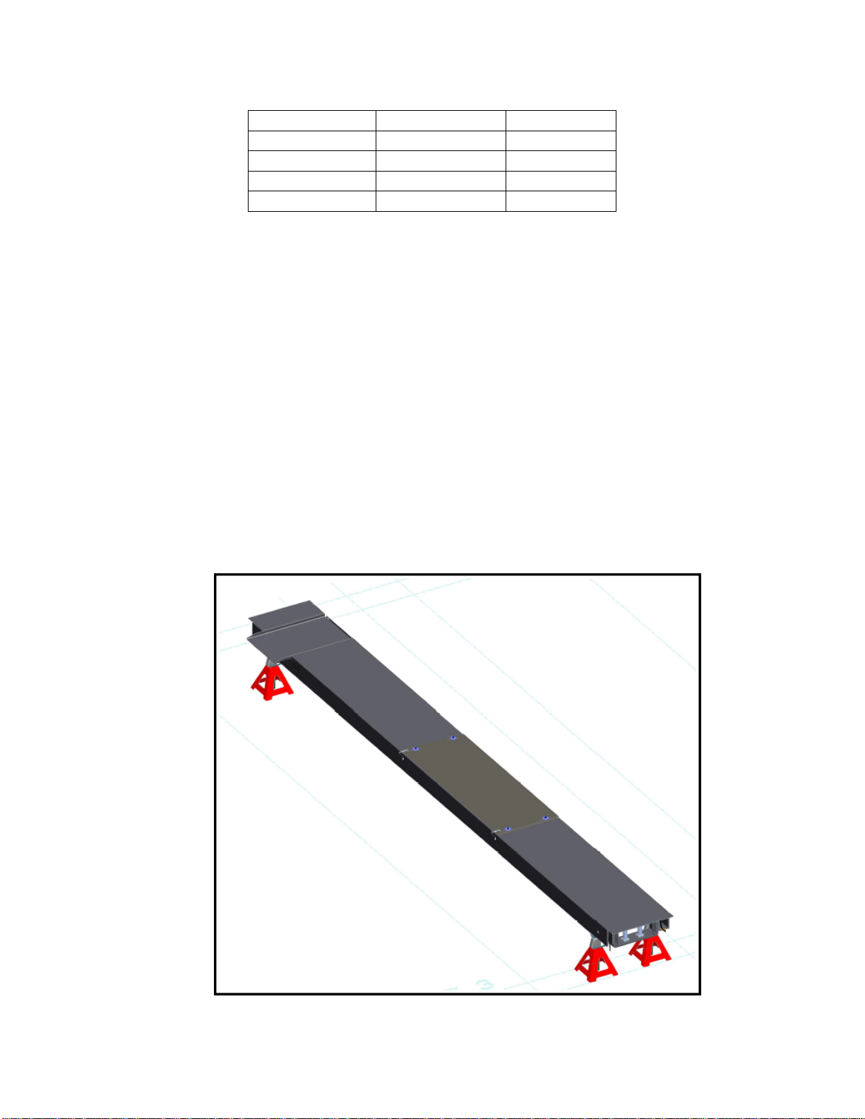
4. Using a floor jack or engine hoist, lift the left side runway and support with (4)
jack stands (see Figure 5) or other means of support. Use the floor jack or
engine hoist as addition support.
5. If possible, repeat for right side deck.
Figure 5: LS Deck Support
Table 2: Cable
Identification

18 of 75
NOTE: THE CYLINDER ROD MUST BE FULLY EXTENDED IN ORDER TO ATTACH
THE NON-THREADED ENDS (SLEEVES) OF THE CABLES TO THE CABLE FLANGE
ON CYLINDER ROD. USE COMPRESSED AIR IN THE SHOP AND AN AIR NOZZLE
AT THE BREATHER END TO EXTEND THE CYLINDER ROD. USE CAUTION AND
PROTECTIVE EQUIPMENT WHEN WORKING WITH COMPRESSED AIR.
6. Loosen the hose clamp on the cable flange and assemble the studded end of
each cable to the flange as shown in Figure 6. Ensure the cable studs are
seated properly in the counterbore. Tighten the hose clamp.
Figure 6. Cable Flange and Cable Assembly
7. Use Figure 7 as reference during the rear pulley stack and cable assembly.
Each cable will enter the pulley stack in the middle of the runway and wrap
around the pulley 90 degree (for rear) or 180 degrees (for front).
8. Remove the pulley pins and hardware from rear of runway.
9. Referring to Figure 7 and Figure 8, assemble the left side of the pulley stack, as
shown, with cables 2-1363 & 2-1360 starting from the bottom of the stack and
working to the top.

19 of 75
Assemble lower thrust washer and pulley and reinstall the pulley pin to
hold these in place.
Assemble four more thrust washers (as shown) and the top pulley with
front left cable 2-1360 wrapped around the pulley. Push pulley pin further
up to hold these in place.
Install remaining thrust washers and 1" spacer then complete assembly of
pulley pin and lock in place with hardware.
Install rear right cable 2-1363 around the lower pulley.
Figure 7. Rear Pulley Stack Assembly
Figure 8. Front Left and Rear Right Cable Installed at Rear

20 of 75
10.Referring to Figure 7 and Figure 9, assemble the right side of the pulley stack,
as shown, with cables 2-1362 & 2-1361.
Pass the rear left cable 2-1362 between the two pulleys on the left side
(shown above).
Starting from the bottom right side of the pulley stack, assemble the 1"
spacer, lower thrust washers and pulley. Reinstall the pulley pin to hold
these in place. Wrap around the front right cable 2-1362 on to the pulley.
Assemble four thrust washers as shown and the top pulley with front right
cable 2-1361 wrapped around the pulley. Push pulley pin further up to
hold these in place.
Add remaining single thrust washer and complete installation of pulley
pin and hardware to secure.
Note: If top thrust washer does not fit, remove one thrust washer from
middle of assembly.
Figure 9. Front Right and Rear Left Cable Installed at Rear
11. Use Figure 10 as reference during the front pulley stack and cable assembly.
This manual suits for next models
1
Table of contents
Other Snap-on Equipment Lifting System manuals


Popular Lifting System manuals by other brands


BLUM
BLUM AVENTOS HF manual

Car Oil System
Car Oil System RPB 35.11 Service handbook

FACAL
FACAL DOGE 80 Use and maintenance handbook

Harbor Freight Tools
Harbor Freight Tools Haulmaster Owner's manual & safety instructions

twin busch
twin busch TW 250 Installation, operation, and parts manual

Genie
Genie Z-30/20N Service and repair manual


