SICE S 65E User manual

MANUALE DI ASSISTENZA TECNICA
SERVICE MANUAL
MANUEL D’INSTRUCTIONS
POUR L’ASSISTANCE TECHNIQUE
WERKSTATT-HANDBUCH
MANUAL DE ASISTENCIA TÉCNICA
Ed. 05/2018
S 65E
S 64E

1. ERROR MESSAGES
The machine can recognise a certain number of malfunction conditions and signals them by displaying the relevant messages.
– A – Notice Messages
A 3
wheel not suitable for performing sensitivity calibration - use a wheel of average size (typically 5.5”X1440”) or a larger wheel weighing no more
than 40 kg.
A 5
Incorrect wheel data for an ALU programme. Correct the set dimensions.
A 7
The machine is temporarily not enabled to select the programme requested.
Perform a wheel spin, then repeat the request.
A 20
Internal sensor in an incorrect position during calibration.
• Bring it to the indicated position and repeat the calibration.
External sensor in an incorrect position during calibration.
• carry out the calibration procedure correctly;
• check the external sensor is at 5 +/-1 notch in the rest position;
• in service, check (with the pointer of the external sensor resting on the flange of the swinging unit) that about 167 +/-30 notches are
visualised.
• if the above points are not correct, adjust or replace the potentiometer.
A 23
Incomplete or incorrect data input in Precise ALU/EASY ALU Program. Repeat the input correctly.
A 26
Programme available only after selecting one of the following programmes: ALU 1P / ALU 2P / EASY ALU1/EASY ALU 2 / Motorcycle Dynamic /
Motorcycle ALU, or if selected in Motorcycle Programme but with the wheel NOT in centred position.
A 31
Optimisation procedure (OPT) already launched by another user.
A 41
Incorrect wheel spin procedure on the wheel balancer without guard. The warning appears when the spin button is pressed for more than 10
seconds without pressing the "Start" key at the same time. Release the button and spin the wheel according to the procedure indicated in the
"Wheel Spin (without guard)" paragraph.
Check the proper operation of the spin button and check for damage to the Start key on the keyboard.
A 52
Started procedure for the assembly of the hub automatic wheel locking system. After 60 seconds the procedure ends automatically.
A Stp
Wheel stop during the spin phase.
The rotation of the unit stopped before completing the entire reading cycle:
• check the weight tray does not touch the unit during the spin;
• Check communication between the
MBUGRF
main board and the PEAL32F power board via the control signal ribbon cables (check picoflex
connection - replace cable and/or boards if necessary).
Wheel movement is not integral with swinging unit movement:
• make sure the wheel is tightened correctly.
A Cr
The contact of the micro-switch associated with the guard casing is open.
• check the correct working of the automatic start micro-switch associated with the wheel guard casing (with the guard lowered, the contact of
the switch must be closed);
• Replace the
MBUGRF
main board if the checks described above identified no faulty components.
• Spin performed with guard raised.
• Lower the guard to carry out the spin.
• On machine versions without wheel guard and without the spin button, check that the JUMPER is connected correctly on the main board.
– E – Error messages
E 1
Sensitivity calibration missing. Perform the sensitivity calibration procedure.
• The MBUGRF board has been changed. Perform the sensitivity calibration procedure.
E 2
Error condition on sensitivity calibration. Repeat the sensitivity calibration procedure.
Take particular care NOT to knock the machine during calibration.
Error condition during shaft assembly zero position setting.

First calibrate sensitivity and then set the zero position for the assembly.
If the message persists, check the following:
that the search card reads correctly by performing the encoder test (see paragraph “Service programmes”);
PK modules and phases as indicated in the paragraph “Service Programmes”.
E 3 I/E 2/3
Error condition at end of sensitivity calibration. Repeat the calibration; if the message persists perform the following checks:
Correct sensitivity calibration procedure; Correct fastening and position of the calibration weight;
Check mechanical integrity of the calibration weight;
Check that the search card is reading correctly by performing the encoder test;
PK modules and phases as indicated in the paragraph “Service Programmes”:
Geometry of the wheel used
If the first gramme display function is enabled in the service environment (indicated by “1 ON” in the relative area), the following parameters
are displayed at the end of calibration:
L1= residual wheel unbalance calculated with respect to the barycentre of the calibration weight. The recommended value is less than 100g per
side, otherwise balance the wheel before performing the calibration;
L2= unbalance detected with the calibration weight in position as indicated in the second calibration spin. This value must be 100g +/-5 on the
inner side and less than 5g on the outer side;
L3= unbalance detected with the calibration weight in position as indicated in the third calibration spin. This value must be less than 5g on the
inner side and 100g +/-5 on the outer side.
When error “E 3” is displayed, this means that the grammes acquired by the machine during the second (L2) and/or third spin (L3), are out of
tolerance, therefore the previously described checks must be performed.
E 4
Error condition during calibration of
internal sensor and/or of external sensor (if installed). Calibrate the internal sensor and the external sensor, if present.
E 6
Error condition when executing optimisation programme.
Repeat the procedure from the beginning.
E 12
a) Width sensor not in the rest position when machine was switched on. Switch off the machine, return the sensor to the correct position and
switch back on.
b) External sensor not present or faulty. Visualisation of this error can be disabled by performing the following procedure:
- Select the "Sensor calibration" icon and press Enter.
E 27
Excessive braking time. Check:
• that relay “RL1”, which inverts current for braking, is working correctly. If the relay functions correctly, at the beginning of braking, you will
hear a mechanical tone coming from the power supply card. If not, replace the PEAL32F power supply card;
• check that the motor cables are connected correctly in the 6-pole connector;
• check that the 6-pole connector is connected correctly to the PEAL32F card.
E 28
Encoder counting error.
In this case, check the following:
• check the state of the encoder disc;
• check that the search card reads correctly by performing the encoder test (see paragraph “Service Programmes);
• check that the search card and the Main board are connected correctly with the 8 pole ribbon cable;
• if necessary, replace the search card or the Main board.
E 30
Wheel spin device failure.
Error condition related to the non-rotation of the unit after pressing the START key.
If the wheel begins to rotate:
• check the encoder card is working.
If the motor does not start up:
• check that the motor power supply cable is correctly connected to the PEAL32F power supply card;
• check that the PEAL32F power supply card is working;
• check the motor is working.
E 32
The wheel balancer was jolted during the reading phase. Repeat the spin.
The wheel balancer makes checks on the disturbances; if the machine suffers excessive jolts during the reading of the unbalances, it displays
this error.
If the machine was not knocked, check inside the machine whether:
• the wheel balancer is resting firmly on the floor;
• the swinging unit has noisy bearings;
• the securing ring nut is fastened tightly.
• check that the search card reads correctly by performing the encoder test (see paragraph “Service Programmes");
• check PK modules (see paragraph “Service Programmes“).
CCC CCC

Unbalance values greater than 999 grams.
2. TROUBLESHOOTING
The wheel balancer is equipped with self-test and self-diagnosis programmes supplying information about most possible faults and the relative
interventions (refer to the list of error messages and the paragraph “Troubleshooting” in the User Manual).
There are, however, irregular working conditions that the machine is not able to recognise, and which are listed below.
WARNING!
For all electrical irregularities, before replacing a board you are advised to check:
- the effectiveness of the wiring between those components probably involved in the malfunctioning. In particular, check:
- that the connectors are correctly inserted;
- that the contacts are correctly fixed to the ends of the individual wires of the cables;
- the stability of the mains voltage in the area where the machine is installed and the efficiency of the earthing system of the shop;
- for damage to the protection fuses installed in the power supply panel.
The table below summarises the general wiring diagram.
The machine does not switch on.
Using a voltmeter, check that there is a power supply voltage on the terminal board of the PEAL32F power supply card.
1) If there is no voltage on the PEAL32F card, check:
- that the power socket and the relative protection fuses are in proper working order;
- the correct connection of the plug to the machine power supply cable;
- the mains cable is not damaged;
- the main switch is working correctly.
2) If there is voltage on the PEAL32F card, check:
- the presence of the voltages envisaged on the PEAL32F card, i.e. from 90V to 250V;
- the efficiency of the power supply card, checking:
• that the relative signalling LEDs light up;
- that the power cable of the MBUGRF main board is installed correctly, and that the cable connectors are connected correctly;
- any short-circuits on the peripheral devices. For this purpose, detach all the cables of the connectors of the Mother card, apart from the
power supply one, and try to switch on the machine;
- the monitor is powered. Check:
• the power supply cable is correctly inserted in the power supply panel;
• the green indicator light is switched on;
- the monitor, if correctly powered, is working properly. Check:
• that the signal cable connector is fastened correctly to the MBUGRF board.
- that the cables of the internal and mechanical external sensor (if installed) are installed correctly - specifically, check: connector JSA2 external sensor
cable, JDSI2 internal distance sensor cable.
• Replace the SD board and, if necessary, the MBUGRF board if the checks described above identified no faulty components.
The picture on the monitor is not correctly visualised: it is not centred, not bright enough, there are strange colours, lines etc.
- adjust the registers in the front part of the LCD monitor, referring to the manual supplied together with the monitor;
- check that the monitor signal cable connection to the FPGA graphic card is fastened securely;
-"correctly"resynchronise"the"LCD"monitor"approved"by"the"manufacturer,"as"indicated"in" the"“Monitor"Auto"Setting”"programme" described"in" the" user"
manual.
The image of the monitor is distorted.
- Check that the screen format setting is correct for the monitor installed on the machine (see paragraph “Selecting monitor display format”)
Pressing the START key and/or lowering the guard, the machine does not perform the spin
In this case, the different causes can be distinguished on the basis of the display indications.
1) If the monitor continues to show the unbalance values previously calculated.
The main board is not receiving or perceiving the START signal arriving from the keyboard or the micro-switch.
Check:
• the correct operation of the automatic start micro-switch associated with the wheel guard casing (with the guard lowered, the contact of
the switch must be closed);
• that the automatic start micro-switch is wired correctly
;
• the correct operation of the Start key.
• Replace the
MBUGRF
main board if the checks described above identified no faulty components.
2) If the monitor shows the geometric data of the wheel.
The main board receives the signal from the START key or the micro-switch, but the subsequent command is not carried out.
Check:
- the “command cable” connecting the Mother board to the “PEAL32F power supply card” is correctly inserted and wired;
- that the “PEAL32 power board” is working correctly, as described in paragraph “2.1 PEAL32F power board”. To do this, proceed as follows:
• disconnect the power supply cables of the motor;

- place the terminals of a tester (used as an alternating voltmeter) in contact with the terminals of the disconnected cables;
• press the START key. If the piloting part upstream of the measuring point is working correctly, you should read a voltage value of around
115/230 Volts (based on the type of power supply used).
• the spin motor is not damaged.
Carry out this check using a multimeter on the PHOENIX connector connected to the PEAL32F power supply card:
PIN3 – PIN6 mains voltage (230/115vac) while spinning or braking
PIN4 – PIN5 mains voltage (230/115vac) while spinning or braking
PIN1 – PIN2 zero voltage, i.e. thermal overload circuit breaker closed, spin correct
PIN1 – PIN2 voltage approx. 3VDC, i.e. thermal overload circuit breaker open, spin NOT performed and error message “E 16”
PIN1 GND
PIN2 THERMAL OVERLOAD CIRCUIT BREAKER
If there is NO voltage across Pin3-Pin6 and/or Pin4-Pin5 there is a power supply card fault, whereas if there is voltage but the machine does
not spin, there is a spin motor fault.
- for damage to the coil of relay “RL2”, which is used to power the spin motor. If the relay operates correctly, after pressing START (or lowering
the guard) there will be a mechanical tone coming from the Mother board. Otherwise, replace the PEAL32F power supply card.
If the above checks have not pointed out any faulty components, replace the main board.
For the machine version without a guard, check the proper operation of the Start key on the keyboard and of the button to the side of the
machine. In the rest position, the button contact must be open whereas it must closed when pressed.
3) The monitor displays the message “A Cr”.
The Start button was pressed on the keyboard.
Check:
- that the guard is lowered when a spin is performed (pressing the START button);
• the correct operation of the automatic start micro-switch associated with the wheel guard casing (with the guard lowered, the contact of
the switch must be closed).
- in machine versions without a wheel guard but with an additional START button.
Check soundness of the START button and, if necessary, check soundness of the START key on the keyboard.
- in machine versions without a wheel guard and without an additional START button. Check soundness of the JUMPER plugged into the Mother
board's JMCR1 connector.
If the above checks have not pointed out any faulty components, replace the main board.
4) The monitor show the message “ E 30”.
If you hear a strange noise, check the status of the pinion.
If the wheel starts to rotate normally, check the operation of the encoder card, see paragraph “Service programmes”.
If the motor does not start up:
- check that the motor power supply cable is connected correctly;
- check motor operation.
Pressing the Start button and key, the machine does not perform the spin (wheel balancer version without the guard).
In this case, the different causes can be distinguished on the basis of the display indications.
1) The monitor continue to show previously calculated unbalance values.
The Mother board is not receiving or perceiving the Start signal arriving from the Start button and key.
Check:
- the correct wiring of the START micro-switch;
- the correct operation of the micro-switch and the Start key.
If the above checks have not pointed out any faulty components, replace the main board.
2) If the geometric data of the wheel appear on the monitor.
The Mother board receives the signal from the Start button or key, but the subsequent command is not carried out.
Check:
- For damage to the coil of relay “RL2”, which is used to power the spin motor. If the relay operates correctly, after pressing START (or
lowering the guard) there will be a mechanical tone coming from the Mother board. Otherwise, replace the PEAL32F power supply card.
- for damage to the spin motor, checking that it is powered with the relative mains voltage. In the case of damage, replace the motor.
If the above checks have not pointed out any faulty components, replace the main board.
3) The message “A StP” appears on the monitor.
- Either the Start button or key (or both) was released when the machine was in the spin or acquisition phase.
4) The monitor show the message “E 30”
If you hear a strange noise, check the status of the pinion.
If the wheel starts to rotate, check the operation of the encoder card, see paragraph “Service programmes”.

If the motor does not start up:
- check that the motor power supply cable is connected correctly;
- check motor operation.
If when commanding the spin (or when lowering the guard or pressing the Start key and the button) the wheel turns in the opposite direction
(i.e. toward the operator), replace the PEAL32F power supply card.
In fact this irregularity is caused by the incorrect operation of the relay “RL1”, which manages the inversion of current for wheel braking.
When switched on, the machine is blocked (it does not accept any command)
Check the keyboard is undamaged and is working. In this case, the keyboard itself should be replaced.
When the machine is switched on, the motor is powered
Probably, the relay “RL2” which is used to power the spin motor does not function correctly, i.e. it remains activated permanently. In that case,
replace the PEAL32F power supply card.
The diameter and/or distance values acquired automatically with the sensors diverge from the real values.
Within the service environment, check the efficiency of the sensors (paragraph "Internal and external sensor").
For slight variances (maximum one inch), noted above all with alloy rims of greater thickness than usual, bear in mind the consideration already
outlined in the paragraph specified above.
The width value acquired automatically with the sensors diverges from the real value.
If the potentiometer presents no irregularities, it may be sufficient to carry out a correct calibration of the external sensor.
The wheel balancer produces inconsistent imbalance values for a number of successive spins (differences greater than 3 grammes for imbalance values of
approximately 30 grammes)
Check (in this order):
- the machine is resting firmly on the floor and the feet are undamaged;
- the weight tray is correctly positioned i.e. not rubbing against the bell of the swinging unit during the spin;
- the anchor, fixed to the hub, does not touch the brake during the signal acquisition phase
- the wheel is well blocked on the shaft i.e. there is no sliding between the wheel and the resting flange during the spin phase.
- To check this condition, make two reference marks with a piece of chalk, one on the flange and the other on the wheel, perfectly in line with
each other. Check there has been no reciprocal movement between the two reference points after a few spins;
- the two pick-ups are correctly tightened (refer to the values of the signals visualised on the service page);
- the efficiency of the main board, replacing it with a new one.
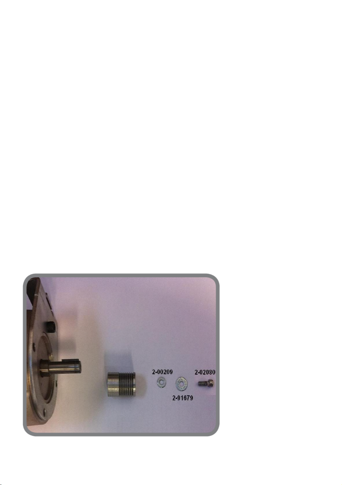
- warns of air in the cylinder when the wheel is clamped. To check, disconnect the pipe (A, Fig.21); there should only be a very small quantity of
residual air in the release circuit. If this is not the case, modify the pneumatic circuit with the kit P/N 5-107159.
If the above checks have produced a favourable result, replace the swinging unit and, if necessary, check for any noise from the bearings.
It is impossible to balance the wheel: applying the weights indicated by the wheel balancer, and performing a check spin, new unbalance values appear at
random
Make the checks listed in the previous point.
Check also:
• that the geometric dimensions set are correct;
• the machine is not out of calibration (carry out the sensitivity calibration procedure);
- the anchor, fixed to the hub, does not touch the brake during the signal reading phase
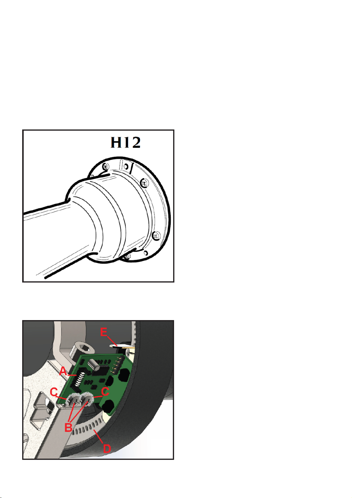
• the cable connecting the search board (encoder) to the main board is correctly inserted and wired;
• the search board (encoder) is working correctly (via the values visualised in service - see the paragraph “Service programmes”). An operational
defect in the search board prevents the machine from correctly calculating the position of the unbalances. In this case it is necessary to check:
• that the photodiodes of the search card are clean;
• the mechanical adjustment of the fork in relation to the search disk.
If the irregularity persists, replace the search board and, if necessary, the search disk (if damaged).
If the fault still does not disappear, replace the main board.
The motor remains activated, keeping the wheel in traction, and the current spin does not end
Perform all checks on the Mother board that were listed in the previous point.
Probably, the relay “RL2” which is used to power the spin motor does not function correctly, i.e. it remains activated permanently. In that case,
replace the PEAL32F power supply card.
If instead after sampling (i.e. acquisition of wheel unbalance signals)in fall, the machine continues to spin the wheel instead of braking, check
the operation of the relay “RL1” which inverts the current for braking.
If the relay functions correctly, at the beginning of braking, you will hear a mechanical tone coming from the power supply card. Otherwise,
replace the PEAL32F power supply card.
During a spin:
• unknown characters appear on the monitor;

Check that the CF was inserted correctly in the graphic card and replace the CF if necessary;
• the machine resets.
The fault (usually sporadic) can arise due to the temporary absence of a power supply to the main board, or owing to a disturbance or
malfunctioning of the main board.
Check:
- the correct wiring of the power supply cable of the main board, and the correct insertion of its connectors;
- the proper operation of the “PEAL32F power supply card”, checking in particular the values of the available power supply voltages (power
supply values from 90 Volts to 270 Volts).
If the above checks have not pointed out any faulty components, replace the main board.
The brake at the end of the cycle is too long, or noisy
Check:
- If the bell of the swinging unit or the motor pulley slides on the belt during the braking phase. Then check the tension of the driving belt
(nominal frequency 200Hz tolerance + 5 / -10Hz);
- check the operation of the relay “RL1”, which inverts the current for braking.
If the relay functions correctly at the end of the cycle, you will hear a mechanical tone coming from the Mother board. Otherwise, replace the
PEAL32F power supply card.
The RPA programme does not function correctly, i.e. the wheel is not stopped in a centred position at the end of the spin or when pressing the Start key with
the guard raised (if present)
Check:
- the state of wear and tear of the brake anchor;
- the distance between the anchor of the hub and the brake (nominal distance 0.2 mm -0/+0.05mm).
The spin device is noisy:
Check:
- If the bell of the swinging unit or the motor pulley slides on the belt during initial acceleration. Then check the tension of the driving belt
(nominal frequency 200Hz tolerance + 5 / -10Hz);
• the motor is not mechanically damaged.
- after removing the belt from the spin motor, check for excessive clearance between the pulley and drive shaft.
If the result is positive, check for wear of the pin and seats on the shaft and pulley.
Replace all parts found to be worn.
Check that all the parts indicated in fig. 1 are installed correctly:
Code 2-00209 washer 4x9mm thickness 1mm;
Code 2-91679 washer 4X12mm thickness 1mm;
Code 2-02080 M4X10.
Now fasten the pulley in the sequence shown in the figure, applying medium strength Loctite thread lock to the 1 M4X10 screw.
fig. 1
Touching the metal parts of the wheel balancer, you get an electric shock

Check the efficiency of the earthing connection of the socket (essential for the correct operation of the machine as well as for safety purposes).
- the earth cable is correctly connected inside the electric system and on the internal machine parts.
3. SOFTWARE CONFIGURATION SUMMARY TABLE
ENCODER
NOTCH
HIDDEN FUNCTIONS
0
Function for electronically resetting the shaft assembly using a
medium/large wheel.
Procedure described in the service manual, “RESETTING THE SHAFT
ASSEMBLY” paragraph
50
Function for enabling/disabling wheel spin with the “Str on/off ” button
for versions without a wheel protective casing.
Procedure described in the service manual paragraph “MACHINE SOFTWARE
CONFIGURATIONS”.
55
Neutral Logo or Logo1 or 2 setting
Procedure described in the service manual paragraph “MACHINE SOFTWARE
CONFIGURATIONS”.
131
Jap/USA/EUr market
To change the threshold to gx5
Procedure described in the service manual paragraph “MACHINE SOFTWARE
CONFIGURATIONS”.
169
Changing the video ratio 4:3, 16:9, 16:10
Procedure described in the service manual, “MACHINE SOFTWARE
CONFIGURATIONS” paragraph
200
Function for calibrating the automatic inner sensor.
Procedure described in the service manual paragraph “INNER SENSOR
CALIBRATION“.
244
Function for enabling wheel spin simulation. Procedure described in the
service manual paragraph “MACHINE SOFTWARE CONFIGURATIONS”.
4. SERVICE PROGRAMMES
The aim of these programmes is to make some data available, to allow the quick and easy checking of the efficiency of the various parts of the
machine.
The data are visualised in the service environment, which is accessed by first selecting the icon .
“Utilities”, then the icon “Configuration programmes”, then the icon “Service program”.
After making the selection, the display will visualise an image showing (from the top):
- the geometric data of the wheel: width, diameter, distance;
- the unbalance values (without thresholds) relating to the last spin made;
- the angular positions (written in white and expressed in notches) of the unbalances relating to the last spin made;
- The software versions installed on the MBU32F board for the CPU (MBU) section of the graphic section (MSK).
- the presence of the threshold of 1 gram for the unbalance values shown. During normal working, when the “gr x 1” unbalance visualisation
mode is selected, the first gram of unbalance is not shown. In this condition, the message “1 OFF” is highlighted in the appropriate window. If,
on the other hand, you wish to visualise the first gram of unbalance as well, you must select the icon.
In this condition, the message “1 ON” is highlighted in the appropriate window.
In this condition, the sensitivity of the machine is also intensified so as to calculate and visualise the unbalance values with the greatest
precision possible.
This characteristic allows you:
to visualise the unbalance values with the maximum precision allowed, so you can balance a wheel perfectly and then carry out further checks
on it.
The technical assistance staff must always work with this condition.
- the presence of the rounding-off (to one inch) of the values obtained with the automatic sensor. When the rounding-off is activated, the
message “ON” is shown in the appropriate window. If you wish to visualise the diameters acquired with the precision of a tenth of an inch, it is
necessary to select the icon. The message “OFF” appears on the display, indicating the setting of this new condition.

This function allows you:
to check with the maximum precision (a tenth of an inch) the match between the values obtained with the sensor and the nominal values of the
wheels.
- The current value of the angular position transducer of the wheel (encoder), its variation interval, and two numerical values corresponding to
the number of impulses counted by the encoder during a spin and the expected value for this count (XXX).
These data allow to:
to easily check the efficiency of the encoder. In particular, that the value of the encoder is continuously updated within the interval 0 - 511
when turning the shaft manually in the two directions, and that the two numerical values visualised on the right of the line are the same at the
end of a spin made in the service environment.
If the two numerical values displayed on the right side of the row are NOT equal, the encoder card must be replaced:
- switch off the machine;
- remove the weight tray;
- remove the card by unscrewing the two fixing screws, then fasten the new encoder card as follows:
a. turn the shaft assembly until the threaded hole in the bell (used for fastening the calibration weight for sensitivity calibration), is positioned at H12 (see
Fig.2).
Fig. 2
b. fasten the search card (A, Fig.2a), so that its base rests on the step on the motor support, using the two screws (B, Fig.2a) and the fastening plate (C, Fig.2a)
provided (tighten the screws in a way that the card can be adjusted), then place the calibration template code 4-130557 (E, Fig.2a) between the card and the
metal disc (D, Fig.2a);
Fig.2a

c. lightly push the search card A in the direction of the metal disc D, tighten the two fastening screws then remove the calibration template.
IMPORTANT:
after any adjustment or after replacing the encoder board, perform the relative test cycle by performing a spin with a wheel, and check that the two numerical
values shown on the right hand side of the row denominated ENCODER TEST in the service environment match.
If replacing this component does not resolve the problem, replace the fork cable (A, Fig.3).
- The values of the transducers / sensors used to obtain the geometric data of the wheel, together with their typical variation intervals.
These data allow to:
to easily check their efficiency. In particular, that when moving the sensor the relative values are continuously modified within the envisaged
intervals (see also paragraph 6):
diameter sensor -110
distance sensor from 0 to 630
if the sensor rod is short (527mm); from 0 to 720
if the sensor rod is long (572mm);
There is a green window to the side of the distance sensor value that displays the message “ON”, which indicates the status of the zero sensor
used for zero-setting the automatic sensor.
This message changes to “OFF” when the internal sensor is extracted and returns to “ON” when it returns to the rest position (reference
distance sensor value 5 +/-1). If this update does not occur, carry out the checks described in the “internal and external sensor” chapter.
width dial setting from 5 to 255, with external sensor installed.
This value is updated by moving the external sensor towards and away from the operator.
External sensor distance from 5 to 1950, with ultrasonic sensor installed.
This value is updated within the operating range of the sensor itself (min. distance 60mm - max. distance 400mm).
- that the wheel guard (COVER) micro-switch is working correctly; OPEN state with wheel guard open, CLOSE state with wheel guard lowered.
- that the PL clamping system pedal (C CONTROL PEDAL) micro-switch is working correctly. OPEN state when the pedal is NOT pressed, PRESS
when the PL pedal is pressed.
These values may be used to determine if the wheel guard micro-switch and the micro-switch of the PL automatic clamping system control
pedal are working correctly.
- speed (rpm) and the number of any discarded periods in the last spin executed.
These data allow to:
check that the spin speed is correct (rpm), using an average sized wheel (typically 5.5” x 14”) - speed value must be within the range from 95-
105.
check for interference during the spin. If there is a number different from 0/X (where X is the number of sampled periods during the spin)
repeat the spin, taking care not to knock the wheel balancer during the readout phase.
If the machine was not knocked, check inside the machine whether:
• the wheel balancer is resting firmly on the floor;
• the shaft assembly has noisy bearings;
• the securing ring nut is fastened tightly;
• the anchor fixed to the hub is not touching the brake, and the clutch in the electromechanical locking system is not touching the anchor fixed
to the cone of the internal device during the signal acquisition phase.
- the following numerical values:
1. amplitude and phase of the signal generated by the internal pick-up.
2. amplitude and phase of the signal generated by the external pick-up.
3. the phase displacement (in relation to the reference value of 180 degrees) of the signal of the external pick-up compared with that of the
internal pick-up. The value is expressed in encoder notches (whole part) and in tenths of a notch (decimal part). One encoder notch
corresponds to about 1.4 degrees.
4. to visualise or update the values, it is necessary to:
- to calibrate with the 100 g weight, mount a previously balanced medium sized wheel (5.5”X14”) on the swinging unit (after selecting “1
ON” mode with the icon) and apply the calibration weight (100 g) on the external side;
- to calibrate with the SLUG calibration counterweight, mount a previously balanced medium sized wheel (typically 5.5”X14”) or a larger
wheel, but with a mass NOT exceeding 40 Kg. Apply the SLUG (calibration weight) in the position indicated in the figure:

- perform a spin.
The values visualised do not depend on the dimensions set.
These data allow to:
• to check that the values visualised are within the envisaged intervals, i.e. (see also the paragraph “Pick-up replacement and adjustment”):
- internal pick-up signal: > 200
- external “ “ “ : > 100
- difference between pick-up phases: from -2.0 to + 2.0
- the phase calibration coefficient.
This value makes it possible to:
to check that the value visualised is within the envisaged interval, i.e. from -2.0 to +2.0.
You can exit the service environment by selecting the programme exit icon.
If the pick-up phase difference is not within the specified range (+/-2), check that the search board is reading correctly by conducting the test described previously.
The aim of these programmes is to make some data available, to allow the quick and easy checking of the efficiency of the various parts of the
machine.
5. ELECTRICAL BOX BOARDS

fig. 3
5.1 PEAL 32F power board
This power board enables the wheel balancer to be powered with single phase AC mains power with a voltage of 100 - 240 Volts +/- 10% (20
fig.3).
The following LEDs must illuminate after power-on:
- LED LD1 (green) must be lit (indicates that board is receiving 5VDC power),
- LED LD20 (green) must be lit (indicates that Sonar sensor is receiving 24VDC power),
if these LEDs are not lit, check that the board is receiving power correctly.
The following red LEDS light up in sequence when a spin is performed:
• LD2 indicates the power supply to the spin motor (115/230VAC);
• LD3 indicates the end of spin braking with inversion of current mode;
• LD4 FR_ST indicates clamping braking or braking in a centred position if the RPA programme is enabled.
5.2 “MBUGRF” CPU board
- LD1 = green +5V board power supply presence LED
- LDG35 = Graphic module output green +3.3V power supply presence LED (if off, problem with graphic module)
the other LEDs must always be off (currently not managed)
If the LED is off, check the following in the order given:
- that the PEAL32F board is functioning correctly;
- that the power cable from the PEAL32F board (O, Fig.3) is connected correctly.
- replace the power cable (O, Fig.3);
- replace the MBUGRF board (2, Fig.3);.
TEST POINTS ON BOARD
U10 +5V = +4.75V to +5.25V
NOTE
The SD board on the MBUGRF (25, Fig. 3) must be configured as shown in figure 4 (NO LOCK).
Otherwise, the machine will NOT acquire any changes/settings.

fig. 4
After switch-on. the machine loads the graphics. This operation, which lasts approx. 25 seconds, results in the display of a logo with a clock on
the monitor
if the "clock" logo is displayed for longer, check the correct loading of the SD and replace it if necessary.
If the “clock” logo does not appear after switch-on, check:
- the connection of the monitor power supply cable;
- connection of the monitor signal cable (L, Fig.3) to connector on MBUGRF board;
- the correct functioning of the MBUGRF board;
- The correct insertion of the SD in the JSD1 connector.
5.3 WHEEL ENCODER board
Fig. 4a
Perform the ENCODER TEST to check that the encoder board functions correctly (chap. Service Programmes)
6. HARDWARE CONFIGURATION OF MBE32F MAIN BOARD
On the boards used in the wheel balancer, there are certain hardware (dip switch and jumpers) settings that allow them to be used on different
models. According to the code of the requested spare part, the board is configured in the factory. During the installation phase, it is
recommended not to modify these configurations for any reason.
7. MACHINE SOFTWARE CONFIGURATIONS
When replacing the MBUGRF CPU board or performing the board reset diagnostic test “t5”, the wheel balancer must be configured correctly for
the specific machine version.
Configure the wheel balancer as follows:
7.1 Enabling wheel spin with button
-access the service environment and, turning the unit, position it to encoder position notch 50;
-Remaining on this notch, hold down the Enter button (with the cursor on the “spin counter” icon) for approx. 5 seconds. A window with the
message “Start OFF” appears on the monitor;
- Press Enter to enable the wheel spin with a button; the message “on” appears on the monitor;

- Press the Escape key to exit.
7.2 Selecting monitor display format
This function may be used to change the screen format to suit the monitor used.
- access the service environment and, turning the unit, position it to encoder position notch 169;
- while still at this notch, press and hold ENTER (with the cursor on the “spin counter” icon) for approximately 5 seconds. A window with the
following message is displayed on the monitor:
“Video 4:3” (default setting)
- Press ENTER again to cycle through the following modes:
16:10
16:9
- select the desired screen format, then press ESCAPE to confirm and exit.
IMPORTANT: some configurations may be performed as follows:
• Select the “Utility programmes” icon.
• Press and hold the STOP button for at least 10 seconds. A window opens on the screen with the letters “CFG X” where X is the number of the
configuration on the board;
• Use the arrow buttons or enter key to change the type of machine configuration.
• Press the ESC key to exit.
• The table below shows the different selectable configurations:
IMPORTANT: after configuring the machine as described above and after pressing the Escape key to confirm/exit, turn the machine off and on
with the main switch located at the back.
7.3 Setting imbalance threshold for market
- enter the service environment and, turning the unit, position to notch 131;
- Remaining on this notch, hold down the Enter button (with the cursor on the “spin counter” icon) for approx. 5 seconds. A window with the
message “SEL EUr” (factory setting) is displayed on the monitor;
- Press ENTER to change the market (refer to the working zone), the message “USA” or “JAP” (Japan) will appear on the monitor;
- Press the ESCAPE key to exit and confirm the selection that was made.
7.4 Enabling wheel spin simulation
This programme makes it possible to perform subsequent wheel spins in automatic mode by setting a fixed time (seconds). This setting may be
used to check over time if there are any mechanical or electronic machine anomalies.
- access the service environment and, turning the unit, position it to notch 244;
- Remaining on this notch, hold down the Enter button (with the cursor on the “spin counter” icon) for approx. 5 seconds. A window with the
message “Delay= 10” appears on the monitor.
- Press the arrow keys to change the pause time between one spin and the next one. It is possible to change this time from a minimum of 5
seconds to a maximum of 180 seconds.
- Press ENTER to start the wheel spin simulation cycle.
- Press the ESCAPE key to stop the cycle and exit.
7.5 Enabling Neutral Logo setting
- access the service environment and, turning the unit, position it to encoder position notch 55;
- Remaining on this notch, hold down the Enter button (with the cursor on the “spin counter” icon) for approx. 5 seconds. A window with the
message “Logo XXX” will appear on the monitor, where XXX is the machine setting;
- Press the Enter button to change the machine logo setting. The following settings will appear on the monitor:
Logo STD →manufacturer logo displayed
Logo OFF →manufacturer logo NOT displayed, or specific logo enabled if applicable.
Logo 2 →manufacturer logo NOT displayed
Logo 3 →manufacturer logo NOT displayed
- Press the ESCAPE key to exit.
8. E2PROM MEMORY RESET PROGRAMME
Proceed as follows to perform the E2PROM calibration parameter zero-setting test t5:
Configuration Number
CFG1
(DEFAULT)
CFG2
CFG3
CFG4
CALIBRATION TYPE
SLUG
SLUG
SLUG
100g
MARKET: EUROPE/USA/JAPP
EUROPE
USA
JAPP
EUROPE
UNBALANCE UNIT OF
MEASURE: GRAMS/OUNCES
GRAMS
OUNCES
GRAMS
GRAMS

- With the machine turned off, set the dip-switch (A, figure 5A) which is necessary for accessing the diagnostics mode, i.e:
MBUGRF
: SW1 DSW2 to ON;
- Turn the wheel balancer on;
- The diagnostics programme page “TEST SELECT” will appear on the screen. Use the arrow keys to select the test called “5 E2PROM”;
- Press the enter button to confirm the selection. The board will automatically reset the calibration parameters;
- Once the operation on the screen is completed, the OK message (green) will appear to the side of the previously selected test “5 E2PROM”;
- turn off the machine and return the dip-switch to its original position (all switches are OFF).
9. ZERO-SETTING OF THE SWINGING UNIT
If it is necessary to replace the MBUGRF main board and/or the shaft assembly, after calibrating sensitivity, the zero position of the shaft assembly
itself must be set as follows :
- mount a medium sized wheel (e.g. 5.5”X14”) on the machine with a rim preferably in steel and with a maximum residual unbalance of 10
grams per side;
Important: to properly perform the zero-setting of the swinging unit, the wheel rim must be in perfect condition, without deformations or
abrasions or dirt in the centring hole or on the plane that rests on the swinging unit. In addition, the centring accessories must be correct for
the wheel type and be clean and in perfect condition.
- clamp the wheel on the unit, keeping the valve in the 12 o'clock position;
- enter the wheel dimensions (in manual mode or automatic mode in versions with a digital sensor);
- go to the service environment as described in the “Service Programme” paragraph
- turning the unit position to encoder position notch 0;
- Remaining on this notch, hold down the Enter button (with the cursor on the “spin counter” icon) for approx. 5 seconds. A window with the
message “GRP 0” appears on the monitor;
- perform a spin;
- at the end of the spin, a window with the message “GRP 180” appears on the monitor:
- move the wheel valve to the 6 o'clock position, then keeping the unit in this position, loosen the ring nut and return the wheel valve to the 12
o'clock position;
- Perform a second spin;
- when the spin is complete, the machine will automatically prepare the service environment
- Exit the service environment by pressing the “Escape” key.
- Check that the zero-point has been set correctly for the unit by balancing the wheel. Then, move the wheel valve to the 6 o'clock position and,
keeping the unit in this position, loosen the ring nut and return the wheel valve to the 12 o'clock position;
- perform a spin. The residual unbalance obtained must be max. 3 grams per side, otherwise, repeat the procedure, paying attention to the
indicated positions and the residual unbalance of the used wheel.
10. DISASSEMBLING THE WEIGHT TRAY
TYPE A

Fig. 5
- disassemble the keyboard via the adhesive velcro;
- remove the ground cable and the picoflex connector from the keypad;
- Disconnect the monitor signal and power supply cables;
- remove the panel (C, Fig.5);
- remove the two cables disconnected previously, feeding through the hole on the cover panel D (Fig.5);
-Remove the weight tray cover, unscrewing the four M6 fixing screws.
TYPE B
- disassemble the keyboard via the adhesive velcro;
- remove the ground cable and the picoflex connector from the keypad;
- Disconnect the monitor signal and power supply cables;
- Unscrew the four M6 fastener screws of the weight tray.
11. UPDATING CONTROL UNIT OF MBU AND/OR OF SD OF MBUGRF BOARD
These cards are used for belt transmission wheel balancers.
Card description

- MBUGRF board - Main board, manages the wheel balancer and processes data.
- SD board, manages the graphics of the wheel balancer.
The board is controlled by a microprocessor with relative firmware.
The firmware of the MBUGRF card may be updated during maintenance.
It should be pointed out that:
• - The MBUGRF firmware release is identified in the SERVICE environment under MBU.
- the SD board firmware version is identified in the SERVICE environment under the MSK.
In order to work properly, the boards contained in the wheel balancer must have compatible firmware versions. If one board is replaced or updated,
the other boards MUST be checked and updated if necessary.
The following table indicates compatibility between the MBUGRF and SD boards.
COMPATIBILITY TABLE FOR MBUGRF AND MSK (SD) FW VERSIONS.
Firmware release MBUGRF
Software MSK (SD)
1.0 of
23/09/2015
1.1 of
20/10/2015
1.2 of
27/07/2016
1.3 of
28/07/2016
1.4 of
24/03/2017
1.5 of
19/02/2018"
10.0 of 23/09/2015
X
10.1 of 20/10/2015
X
X
X
10.2 of 14/01/2016 SD 5-121447 rel.10.2
X
X
X
MSK 10.2 of 14/01/2016 + GRF 1.6 of
19/04/2016 SD 5-121447 rel.10.2
X
X
X
MSK 10.4 of 17/01/2017 + GRF 1.6 of
19/04/2016 SD 5-121447 rel.10.4
X
X
The programme denominated
wbs
is required to update the control unit (CPU) of the MBUGRF board. If it is not already installed on the PC to be used for
the update, it can be downloaded as explained below. Then launch the “setup.exe” programme.
Downloading the software and firmware from the internet for card updating
If one or more cards needs to be updated, the Firmware that is required can be downloaded from the internet.
To download the updated firmware and graphics versions, proceed as follows:
Connect to the manufacturer's website.
Select “Private area”.
Enter your username, password and then select “Enter”. Select “Software Updates” in the new screen. Fill in the "Keyword" field using the keyword
corresponding to the Firmware to be downloaded. Example:
- Enter "wbs" to download the programming firmware (wbs) for updating from the PC.
- If you want to download the MBU Firmware enter the name of the machine to be updated.
N.B.
The downloaded files are in a compressed format (.zip) and must therefore be unzipped before they can be used.
MBUGRF Firmware update
The application
wbs
is required to update the firmware. If it is not already installed on the PC to be used for the update, it can be downloaded
beforehand as explained in the previous paragraph. Then launch the “setup.exe” programme to install the programme.
Important: the application WBS is only compatible with Windows 98SE, 2000 and XP Professional operating systems.
WARNING: if a laptop is used to update the board, ensure that the laptop is connected to the mains power supply during the update procedure. Using only
battery power (even if fully charged when starting) may cause the update procedure to fail.
-With the machine switched off set the relative deep switch (A, figure 5A) which is necessary for the programming based on the card to be updated,
i.e.:
- MBUGRF: SW1 DSW1 to ON;

Fig.5A
- Connect the serial cable code 8-21100224 to the “JPS1A” connector of the card itself (see part B figure 5A). The other end of the cable is
connected to the RS232 serial port on the PC. If the PC does not have a RS232 port, use the RS232/USB adapter P/N 8-21100226.
- Turn the wheel balancer on.
- Run the application wbs.
- The following control panel for the wbs.exe programme will now open.
fig. 5B
- Select the folder icon (A, figure 5B) and load the file with the extension .cef relative to the firmware version for the update downloaded
previously from the web.
- Select the Options tab and the COM serial port where the programming cable is connected to the PC, see figure 5C.

Fig.5C
Select Firmware Update (icon B, figure 5B) to start the programming procedure.
Fig.5D
- “100%” is displayed when programming has been completed successfully.
- After the programming procedure, close the application, switch off the machine and return the dip-switch to the original position (all switches
OFF).
- If an error message is displayed, check the serial cable wiring harness and repeat the programming procedure, turning the machine off and
then on.
SAB32F program
- Launch the SAB32F program.
- The following control window of the SAB32F program will now open.

- Select the "OPEN" icon and load the file with the extension .bin of the firmware version to be updated previously downloaded from the
network.
- Select the COM serial port where the programming cable is connected to the PC.
- Select the "START" icon to start programming.
- When the message "OK 100%" appears, this means that the programming has been completed successfully.
- At the end of programming, press the "Close" key to close the program, switch off the machine and return the deep-switch to its original
position (all the switches are OFF).
- In the event that error messages are displayed, check the correct wiring of the serial cable and repeat the programming procedure by
switching the machine off and on again.
IMPORTANT: when the board FIRMWARE update is complete, test the E2PROM to reset the calibration parameters as described in the paragraph “E2PROM
MEMORY RESETTING PROGRAMME”.
After this test, the following operations must be repeated in this order:
1. configure the machine based on the version as described in the paragraph “MACHINE SOFTWARE CONFIGURATIONS”;
2. internal sensor calibration as described in the paragraph “INTERNAL SENSOR CALIBRATION”;
3. Calibrate the external sensor, if installed;
4. machine sensitivity calibration;
5. resetting the group, see paragraph “shaft assembly resetting”.
This manual suits for next models
1
Table of contents
Other SICE Wheel Balancer manuals