Snell & Wilcox ARC130S User manual

ARC130S 060801 Version 1 Issue 1 0.1
Operator’s
Manual
© August 2001
Snell & Wilcox Ltd, Durford Mill, Petersfield, Hampshire, GU31 5AZ, United Kingdom.
Tel: +44(0) 1730 821188. Fax: +44(0) 1730 821199.
ARC130S
Aspect Ratio Converter

ARC130S SECTION 0
ARC130S 060801 Version 1 Issue 1 0.2
Safety Warnings
Always ensure that the unit is properly earthed and power connections correctly made.
This equipment shall be supplied from a power system providing a PROTECTIVE EARTH connection and
having a neutral connection which can be reliably identified.
The power terminals of the IEC mains input connector on the rear panel are
identified as shown below:
E = Protective Earth Conductor
N = Neutral Conductor
L = Live Conductor
Power cable supplied for countries other than the USA
The equipment is normally shipped with a power cable with a standard IEC moulded free socket on one end
and a standard IEC moulded plug on the other. If you are required to remove the moulded mains supply plug,
dispose of the plug immediately in a safe manner. The colour code for the lead is as follows:
GREEN/YELLOW lead connected to E (Protective Earth Conductor)
BLUE lead connected to N (Neutral Conductor)
BROWN lead connected to L (Live Conductor)
Power cable supplied for the USA
The equipment is shipped with a power cord with a standard IEC moulded free socket on one end and a
standard 3-pin plug on the other. If you are required to remove the moulded mains supply plug, dispose of the
plug immediately in a safe manner. The colour code for the lead is as follows:
GREEN lead connected to E (Protective Earth Conductor)
WHITE lead connected to N (Neutral Conductor)
BLACK lead connected to L (Live Conductor)
The terminals of the IEC mains supply
lead are identified as shown opposite:
Note that for equipment that is not fitted with a mains power switch, to comply with BS60950 Clauses 1.7.2 and
2.6.9, the power outlet supplying power to the unit should be close to the unit and easily accessible.
Warnings
Voltages within this unit can be lethal under certain circumstances. Where power
is required to be connected to the unit during servicing great care must be taken
to avoid contact with these voltages.
Maintenance should only be carried out by suitably qualified personnel.
No part of this publication may be transmitted or reproduced in any form or by any means, electronic or
mechanical, including photocopy, recording or any information storage and retrieval system, without
permission being granted, in writing, by the publishers or their authorised agents.

ARC130S SECTION 0
ARC130S 060801 Version 1 Issue 1 0.3
EMC Standards
This unit conforms to the following standards:
Electromagnetic Compatibility-Generic Immunity Standard BS EN 50082-1:1992
The European Standard EN 50082-1:1992 has the status of a British Standard and is related to European
Council Directive 89/336/EEC dated 3rd May 1989.
Electromagnetic Compatibility-Generic Emission Standard BS EN 50081-1:1992
The European Standard EN 50081-1:1992 has the status of a British Standard and is related to European
Council Directive 89/336/EEC dated 3rd May 1989.
Federal Communications Commission Rules Part 15, Class A :1998
Safety Standards
This unit conforms to EN60065:1992 as amended by amendment A1(May 1993) and
amendment A2(March 1994). Specification for safety of technology equipment, including
electrical business equipment.
EMC Performance of Cables and Connectors
Snell & Wilcox products are designed to meet or exceed the requirements of the appropriate European EMC
standards. In order to achieve this performance in real installations it is essential to use cables and connectors
with good EMC characteristics.
All signal connections (including remote control connections) shall be made with screened cables terminated
in connectors having a metal shell. The cable screen shall have a large-area contact with the metal shell.
COAXIAL CABLES
Coaxial cables connections (particularly serial digital video connections) shall be made with high-quality
double-screened coaxial cables such as Belden 8281 or BBC type PSF1/2M.
D-TYPE CONNECTORS
D-type connectors shall have metal shells making good RF contact with the cable screen. Connectors having
"dimples" which improve the contact between the plug and socket shells, are recommended.

ARC130S SECTION 0
ARC130S 060801 Version 1 Issue 1 0.4
About this Manual
This manual covers the following product:
•ARC130S with 8 GPI inputs (via 2 x 9 way D connectors) and 8 GPI outputs via a 25 way D connector
Packing List
The unit is supplied in a dedicated packing carton provided by the manufacturer and should not be accepted if
delivered in inferior or unauthorised materials. Carefully unpack the carton and check for any shipping damage
or shortages.
Any shortages or damage should be reported to the supplier immediately.
Enclosures:
•ARC 130S Aspect Ratio Converter
•Power cable
•Operators Manual
•2 floppy disks containing software for up and down loading ARC configurations to a PC
Software Version Amendments
Notes about Versions Fitted
Firmware. This machine is shipped with version A32 of the firmware.
Floppy Discs Disk 1 ARC Configuration Loader Version 1.0.1
Disk 2 ARC Configuration Loader Version 1.0.1
Manufacturers Notice
Copyright protection claimed includes all forms and matters of copyrightable material and information now
allowed by statutory or judicial law or hereinafter granted, including without limitation, material generated from
the software programs which are displayed on the screen such as icons, screen display looks etc.
Reproduction or disassembly of embedded computer programs or algorithms prohibited.
Copyrighted names:
Microsoft Windows™
Information in this manual and software are subject to change without notice and does not represent a
commitment on the part of Snell & Wilcox Ltd. The software described in this manual is furnished under a
licence agreement and may not be reproduced or copied in any manner without prior agreement with Snell &
Wilcox Ltd. or their authorised agents.

ARC130S SECTION 0
ARC130S 060801 Version 1 Issue 1 0.5
Table of Contents
Section 1 Introduction
Section 2 Specification
Section 3 Installation
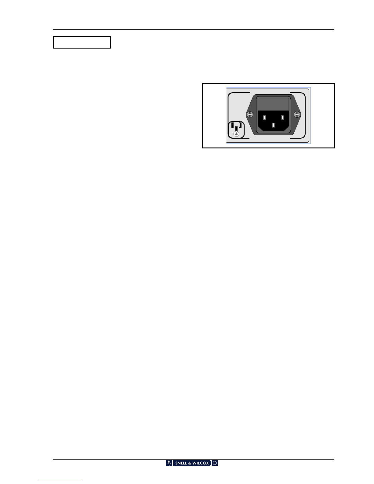
Power Connections .......................................................................................................... 3.1
Environment .....................................................................................................................3.1
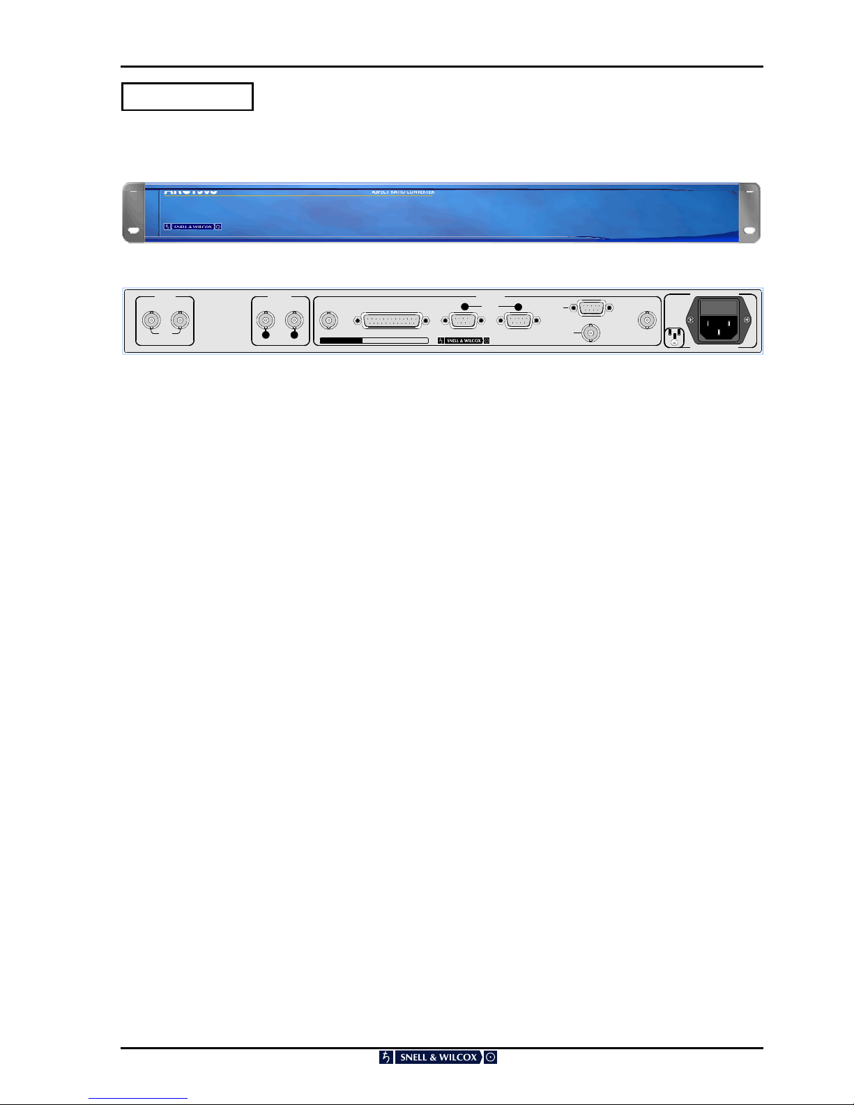
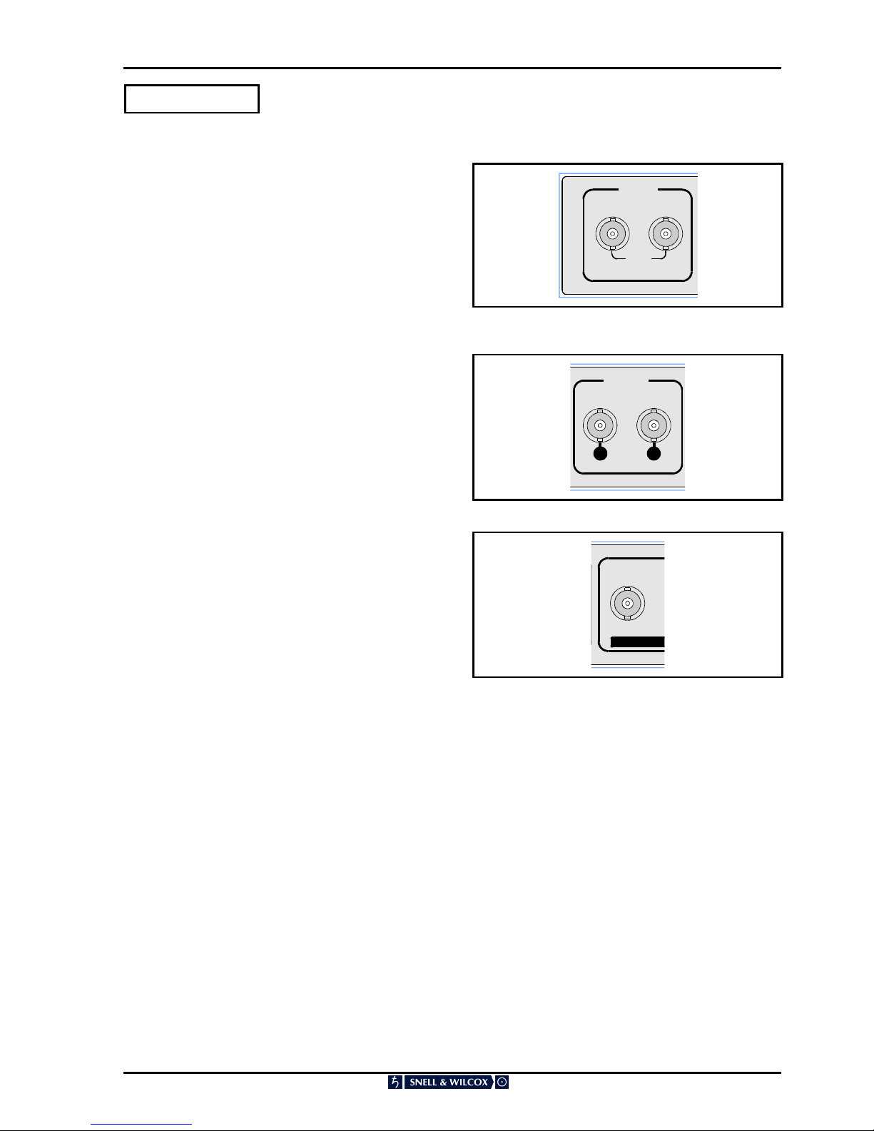
Rear Panel Connections .................................................................................................. 3.2
Using a Kudos Active Front Panel fitted to a Shoebox..................................................... 3.5
GPI Connections .............................................................................................................. 3.6
ARC Configuration Loader Program ................................................................................ 3.8
Switching On ....................................................................................................................3.10
Section 4 Operation
Introduction....................................................................................................................... 4.1
Switch Controls (Blank Front Panel) ................................................................................ 4.1
Top Menu ............................................................................................................... 4.2
Audio ...................................................................................................................... 4.3
Blanking ................................................................................................................. 4.4
Display ................................................................................................................... 4.5
GPI ......................................................................................................................... 4.10
Auto Setup ............................................................................................................. 4.11
Line 23 (PAL Standard Only) ................................................................................. 4.14
AFD Dat ................................................................................................................. 4.15
Memory .................................................................................................................. 4.17
Setup...................................................................................................................... 4.18
VITS ....................................................................................................................... 4.23
Option with Front Panel Controls ..................................................................................... 4.24
Function Select ...................................................................................................... 4.25
Display ................................................................................................................... 4.25
VITS ....................................................................................................................... 4.27
Auto........................................................................................................................ 4.27
Setup...................................................................................................................... 4.28
GPI ......................................................................................................................... 4.30
Bypass ................................................................................................................... 4.36
User........................................................................................................................ 4.36
Aspect Ratio Selection ........................................................................................... 4.37
Blanking Setup ....................................................................................................... 4.46
Line 23 Setup ......................................................................................................... 4.47
Video Index Setup.................................................................................................. 4.48
Appendix – Video Index and Enhanced Line 23 .................................................... 4.50
Operation via a Kudos Active Front Panel
Protocol .................................................................................................................. 4.53
RollCall Menu System Drawing.............................................................................. 4.54
Menu Details .......................................................................................................... 4.55
Section 5 System Overview ........................................................................................................... 5.1
Block Diagram Description............................................................................................... 5.2
Section 6 Aspect Ratio Technical Codes for Video and Picture Sources

ARC130S SECTION 0
ARC130S 060801 Version 1 Issue 1 0.6
Manual Revision Record
Date Version No. Issue No. Change Comments
060801 1 1 First issue of manual

ARC130S SECTION 1
Introduction
ARC130S 060801 Version 1 Issue 1 1.1
Aspect Ratio Converter ARC130S
Front Panel View
INPUT
SERIAL DIGITAL
MADE IN ENGLAND
REMOTE
CONTROL
DELAY
1
ACTIVE
LOOP
OUTPUT
SERIAL DIGITAL
12
AC INPUT
AUTO SELECT
115/230V
1.2/0.6A
45-60Hz
FUSE
T2.5A
ROLLCALL
RS-422
EDH GPI OUT GPI IN 11
2
M
MM
Mo
oo
od
dd
de
ee
el
ll
l:
::
:
A
AA
AR
RR
RC
CC
C
1
11
13
33
30
00
0S
SS
SS
SS
Se
ee
er
rr
ri
ii
ia
aa
al
ll
l
N
NN
No
oo
o.
..
.
Rear Panel View
The ARC130S is a compact Broadcast-Quality
Aspect Ratio Converter with serial digital inputs
and outputs. It will aspect ratio convert in both
directions, e.g. 16:9 to 4:3 or 4:3 to 16:9, and
allows the picture area required for transmission to
be selected from the input picture.
There are twelve preset conversion ratios plus
ratios set up by the user. The user ratios can be
stored in twelve memories and are quickly
pushbutton selected when required for use.
The aspect ratio can also be remotely controlled
either via an RS-422 port, RollCall or from contact
closures via a General Purpose Interface (GPI).
The ARC130S is designed to fit in Continuity
Suites, Studio’s, Outside Broadcast Vans, etc.
It facilitates the production of master tapes for
broadcast using PAL+, D2MAC and digital
transmissions. It facilitates postproduction and
presentation of tapes mastered in 16:9 format
through the current 4:3 format transmission
system.
The ARC130S is a compact 1RU high unit for
location on the desktop or in a 19-in. rack. It will
operate in 525 and 625 line systems.
Vertical interval information is passed without
conversion.

ARC130S SECTION 2
ARC123S 060801 Version 1 Issue 1 2.1
Specifications
Features
Signal Inputs
Serial Digital 1 Serial D1 525 or 625 via BNC
loop-through connectors
Remote Control 9 way D-Type
GPI 2 via 9 way D-Type
Network Control RollCall via BNC connector
Signal Outputs
Serial 2 sets of Serial Digital D1 via BNC
connectors
Delay 1 Output via BNC connector
GPI via 25 way D-Type
Control
Functions
Blanking: Controls blanking on both input
and output
Display Position, Size and Aspect Ratio
Enhanced Line 23
Setup Input/Output Setup
Video Index Input/Output Setup
Memory Stores settings in memory and
allows recall of memorized
settings
VITS VITS blanking
SETUP Audio, Clipping, Freeze, Gamut
Limiting, GPI, GPI Program, Input
Loss, Input Standard (625, 525),
Process, Test Pattern, Field
Pairing Mode and line 21 video
(525 line systems).
BYPASS Non-interpolated output
USER User display memories
Output Aspect Ratio Letterbox: 16:9, 1.85:1, 1.66:1,
14:9.
Full Screen: 16:9, 1.85:1, 1.66:1,
16:9 anamorphic
4:3 Curtains, 14:9 Curtains, 4:3
Full Width, 16:9 full Width
Specifications
Input Standard 525/625 line
Serial Input Return
Loss better than 15 dB to 270 MHz
Serial Output Return
Loss better than 15 dB to 270 MHz
Power
Input Voltage Range 90 V to 260 V 45/90 Hz
Consumption 75 W maximum
Mains Fuse Rating 2.5 AT
Mechanical
Temperature Range 0 to 40° C operating
Case Type 1U Rack Mounting
Dimensions 483 mm x 530 mm x 44 mm
(w,d,h)
Weight 7 kg

ARC130S SECTION 3
Installation
ARC130S 060801 Version 1 Issue 1 3.1
POWER CONNECTIONS
Power Supply
Mains power is supplied to the unit via a filtered
IEC connector with integral fuse holder. The fuse
rating is 2.5 A (T).
The unit automatically senses the supply voltage in
the ranges 90V-132V and 176V-264V and sets
itself up accordingly. No voltage adjustment
procedure is required.
ENVIRONMENT
The unit is ruggedly constructed to meet the
normal environmental requirements. It is important
that there is a free flow of air at both sides of the
unit to dissipate the heat produced during
operation. Installations should be designed to allow
for this.
If the unit is to be rack mounted, first open the front
panel by lifting up the the two levers at right and left
of the panel, hinge the panel down and
AC INPUT
AUTO SELECT
115/230V
1.2/0.6A
45-60Hz
FUSE
T2.5A
pull it forward. The fixing “ears” behind the panel
will be revealed and the unit can be mounted in the
rack. Refit or close the front panel by pushing it
back into position (the levers will click into place).
The rear of the base includes additional fixing
holes on either side to allow a rear support to be
added.

ARC130S SECTION 3
Installation
ARC130S 060801 Version 1 Issue 1 3.2
REAR PANEL CONNECTIONS
Digital Input
A BNC connector is provided for the serial digital
input, with an active loop-though BNC connector
also fitted.
Digital Output
Two BNC connectors are provided for the serial
digital outputs.
EDH
This connector has no function; connections
should not be made to this connector.
INPUT
SERIAL DIGITAL
ACTIVE
LOOP
1
OUTPUT
SERIAL DIGITAL
12
EDH
M
MM
Mo
oo
od
dd
de
ee
el
ll
l:
::
:
A
AA
AR
RR
RC
CC
C

ARC130S SECTION 3
Installation
ARC130S 060801 Version 1 Issue 1 3.3
Delay Output
Because the ARC130S contains a synchroniser,
the through delay depends upon the setting of
vertical genlock timing.
If the input and output video are co-timed, then the
delay through the ARC130S is four fields (80 ms
for 625 line systems and 66.7 ms for 525 line
systems). If the input and output video are not co-
timed then the range of delay through the ARC is
3.5 to 4.5 fields.
The delay pulse output from the ARC130S
accurately represents the delay through the unit.
The pulse is high for a period equal to the delay
through the ARC. It can be connected to a Snell
and Wilcox audio delay module to automatically set
a compensating audio delay.
If the ARC130S is put into Bypass mode or, field
pairing mode, then the nominal delay remains at
four fields. However because the unit acts as a
frame synchroniser in these modes, the delay
range of the unit is now increased to between 3
and 5 fields.
DELAY

ARC130S SECTION 3
Installation
ARC130S 060801 Version 1 Issue 1 3.4
Remote Control
The unit can be controlled from the special remote
panel option via an RS-422-A D-type connector
(see Table - RS-422-A Remote Connections)
If a remote panel is connected to the RS-422-A
port, set the “Front Panel/Remote Comms/
Auxiliary switch on the ARCOPI2A card to “FRP &
REM” (centre), see Fig. 3.1
The front panel can be disabled by setting the
switch to REM (right hand position) see Fig. 3.1
RS-422-A Remote (Master) Connections
Pin Function Direction
1
2
3
4
5
6
7
8
9
Ground
Transmit –
Receive +
Rec Sig Common
Spare
Trans Sig Common
Transmit +
Receive –
Ground
ARC Remote
ARC çRemote
ARC Remote
ARC çRemote
The Baud Rate is 38.4Kbs, half duplex. Format is 1
start bit, 7 data bits, 1 parity bit, 1 stop bit.

ARC130S SECTION 3
Installation
ARC130S 060801 Version 1 Issue 1 3.5
OPERATION FROM A KUDOS ACTIVE FRONT PANEL FITTED TO A SHOEBOX
OPERATIONAL OVERVIEW
The ARC130S has provision to be remotely
controlled via two different interfaces, either S&W
RollCall, or RS422.
Interface to the "RollCall" communications network
is via the single BNC connector. Connections
should be made by means of a `T' piece (Zo=75
Ohms) to a 75 Ohm cable system as shown below.
It should be noted that both extremities of the cable
system must be terminated in 75 Ohms and the
maximum number of units limited to 240 on one
single cable run.
The communications network is a specially
designed remote control network system and many
more units can be accommodated by using a
"Network Bridge". Remote control can come from
either a dedicated front panel or "shoe-box" or a
standard IBM compatible PC. Full protocol
documentation and more detailed information is
available on request from the supplier.
The RS 422 remote control interface is via the 9-
pin female `D' connector. Protocol information is
also available on request from the supplier.
For more detailed information about the operation
of the remote panel or PC software please consult
their relevant manuals. e.g. Shoebox operator’s
manual.
For specific information about the RollCall menu
system for the ARC130S see Section 4, Operation,
RollCall Menu System on page 4.34
BASIC ROLLCALL OPERATION
All the features from the menu system are
available remotely with the same options structure.
This maintains compatibility and facilitates easy
operation for users familiar with the unit.
The most common remote configuration is shown
below where many units are connected to the
network for remote control by one remote panel or
"shoe-box".
Typical Set-up
The network address for the ARC is set using the
switches SW3 and SW4 on the Output Interface
card. See fig 3.1 on page 3.8.
Parameter changes are reflected both locally and
remotely. For example, if the output is changed to
the colour bars test pattern by a remote unit then
any further access from the card edge to the
PATTERN TYPE option will indicate this change.
Similarly, if the card edge changes a parameter
then this will be reflected on the display panel of
the remote unit.

ARC130S SECTION 3
Installation
ARC130S 060801 Version 1 Issue 1 3.6
GPI
GPI functions are implemented as follows:
GPI Inputs
MADE IN ENGLAND
CONTROL
GPI IN 11
2
These are accessed via two 9-way D type
connectors labelled 1 and 2. Each connector has 4
inputs and connections are as below.
GPI = GPI input
GPI input 1
Pin 2 GPI 0 signal
Pin 6 GPI 0 return
Pin 3 GPI 1 signal
Pin 7 GPI 1 return
Pin 4 GPI 2 signal
Pin 8 GPI 2 return
Pin 5 GPI 3 signal
Pin 9 GPI 3 return
Pin 1 safety ground.
GPI input 2
Pin 2 GPI 4 signal
Pin 6 GPI 4 return
Pin 3 GPI 5 signal
Pin 7 GPI 5 return
Pin 4 GPI 6 signal
Pin 8 GPI 6 return
Pin 5 GPI 7 signal
Pin 9 GPI 7 return
Pin 1 ground.
GPI Outputs
GPI OUT
1
11
13
33
30
00
0S
SS
SS
SS
Se
ee
er
rr
ri
ii
ia
aa
al
ll
l
N
NN
No
oo
o.
..
.
These are accessed via a 25-way D type connector
and connections are as follows:
GPO = GPI output
Pin 2 GPO 0 signal
Pin 14 GPO 0 return
Pin 3 GPO 1 signal
Pin 15 GPO 1 return
Pin 4 GPO 2 signal
Pin 16 GPO 2 return
Pin 5 GPO 3 signal
Pin 17 GPO 3 return
Pin 6 GPO 4 signal
Pin 18 GPO 4 return
Pin 7 GPO 5 signal
Pin 19 GPO 5 return
Pin 8 GPO 6 signal
Pin 20 GPO 6 return
Pin 9 GPO 7 signal
Pin 21 GPO 7 return
Pins 1,10,11,12,13,22,23,24,25 ground
The GPO output characteristics are as follows:
Operating Voltage Range 0 to ±60 V
(DC/AC peak)
Maximum Load current 1.0 A (AC/DC)
Maximum On-State
Resistance @ Tamb =+25°C
500 mOhm
Minimum Off-State
Resistance
@Tamb =+25°C,V=±48V
100 MOhm

ARC130S SECTION 3
Installation
ARC130S 060801 Version 1 Issue 1 3.7
GPI Overview
The GPO provides contact closure tally outputs
that can be used to turn on lamps etc.
GPO 0 tracks GPI 0 so if the display memory that
GPI 0 recalls is active then GPO 0 will close.
Similarly, GPO 1 tracks GPI 1 etc.
This functions even if the GPI inputs have been
assigned different recall memories and if the
memory was recalled via a front panel button
rather than via the GPI.
So, if GPI 3 recalls AUTO, then whenever AUTO is
selected GPO 3 will be closed.
In GPI binary mode, the four LSB’s (GPO 0 to
GPO 3) GPI contacts indicate the binary GPI
memory in use. The four MSB’s (GPO 4 to GPO 7)
contacts are closed if a GPI binary memory is
being used; otherwise they are open.
If a non-binary GPI memory is being used all 8
contacts will be open.
GPI interface Delay
The GPI interface on the ARC130S has a delay
that matches the video processing delay through
the ARC.
This means that if a given input-video field is
desired to produce the first output-field built with a
new aspect ratio conversion; the GPI contacts that
recall that new aspect ratio conversion should be
closed during the field when that video field is
present at the ARC130S input.
Ideally, the contact should be closed a few lines
after the vertical sync group of the reference video,
and, should remain closed for at least one field
period.

ARC130S SECTION 3
Installation
ARC130S 060801 Version 1 Issue 1 3.8
Included with ARC130S software version A32 are 2 floppy disks containing software for up and down
loading ARC configurations to a PC.
ARC Configuration Loader Program
The downloading and uploading of ARC
configuration files is made possible by the
Windows program ‘ARC Configuration Loader’.
Data contained in existing ARC configuration files
(held on the PC) may be downloaded to the ARC
or, ARC hardware configurations may be uploaded
to the PC. The configuration files held on the PC
are in a simple ASCII text format. The
configuration files contain all parameters held in
the ARC. This includes all display memories of all
types that the user can program. This allows the
user to configure an ARC once and then, send that
same configuration to multiple units. Also, if the
ARC software is upgraded, the user can store the
ARC configuration before the upgrade and then
download it afterwards so that the configuration
does not have to be re-done.
The ARC Loader program uses the ARC RollCall
network BNC connection. Thus, the user must
have a means of connecting to the ARC RollCall
BNC before the program can be used. Therefore a
RollCall ‘Shoebox’ or a PC equipped with the high
speed RollCall network card must be available.
The ARC loader program is designed to work with
ARC software version A28 and onwards. Note that
software versions A24 and onwards allow the user
to upload the configuration data from the ARC to
the PC but, the download operation can fail. This
will allow users of software versions A24 to A27 to
capture their ARC configurations before upgrading
to A28.
ARC Configuration Loader Installation
The distribution of the ARC Configuration Loader
includes a setup.exe program file. This file is kept
on the floppy disk labelled DISK1. Running the
ARC Configuration Loader setup.exe, either by
mouse click from within Windows Explorer, or from
the Windows Start\Run menu, will commence the
setup sequence. SETUP SHOULD ONLY BE RUN
LOCALLY TO THE TARGET HOST MACHINE,
this may be achieved either by installing locally
from floppy disk or, by copying the installation files
to a local, temporary directory and running setup
from there. The ARC Configuration Loader
requires the RollCall server program RollOLE to be
pre-installed. The ARC Configuration Loader setup
program searches for a registered installation of
RollOLE prior to commencing its own installation
sequence. If the RollOLE executable is found and
validated then ARC Configuration Loader will
install. Conversely, if setup is unable to find or
validate RollOLE.exe it will inform the operator of
the requirement to install, or re-install, RollOLE and
then setup will exit. The installation of RollOLE
should then be carried out before re-attempting to
run the ARC Configuration Loader setup program.
A compatibility issue has arisen in that RollOLE
makes use of Windows Dynamic Link Library (.dll)
files, the current RollOLE is compatible with the
Library files required to run Internet Explorer (IE)
4.0 or later. Earlier versions of RollOLE will not run
correctly on systems that have installed on them
IE4.0, conversely, the current version of RollOLE
cannot run using the .dll files found on a system
using IE3.x or earlier. The setup program will
therefore detect the absence of IE, or if present the
version of IE, and may accordingly give the
operator the option to continue to load the ARC
Configuration Loader, or exit if a configuration not
suited to RollOLE is detected. This is only an issue
for systems running Win95, as Win98 and
WinNT4.0 implicitly use IE4.0 or later.

ARC130S SECTION 3
Installation
ARC130S 060801 Version 1 Issue 1 3.9
ARC Configuration Loader Operation
The ARC Configuration Loader program can be
run by double clicking on it from Explorer or via the
START menu. When the program is run the User
needs to set two parameters and then up and
downloading may begin.
1. Configuration File Name
This is the name of the file on the PC that the user
wishes to access. If an Upload is undertaken then
the data from the ARC will be stored in this file. If a
Download is undertaken then data from this file will
be sent to the ARC. A valid filename must be
chosen before an Upload or Download can be
undertaken. Note, the file extension must be .TXT.
The filename can be typed in or, the Browse button
may be used to navigate to the desired file.
2. ARC Address
This allows the user to select which ARC on the
RollCall network the program will connect to. The
user must select an ARC before an Upload or
Download can be undertaken. The find module
button should be clicked to navigate to the desired
unit.
3. Download
Clicking this button will send a configuration file
from the PC to the chosen ARC.
4. Upload
Clicking this button will send configuration data
from the ARC to the selected PC file.
Program Menu Selections
The following Menu selections are available to
operators of the ARC Configuration Loader:
1. File: Exit
Ends the ARC Configuration Loader Program.
2. Help: About
Provides Information about the ARC Configuration
Loader including version data

ARC130S SECTION 3
Installation
ARC130S 060801 Version 1 Issue 1 3.10
SWITCHING ON
Check that power is connected to the unit and is
switched on. Open the front panel by pushing up
the levers at the ends of the panel, and hinging the
panel down and sliding partly out.
Set the switch on the Power Unit (see fig. 3.1) to
on. Check that the indicator lamp illuminates green
and the alpha-numeric display is active.
Fig. 3.1 PCB Locations ARC 130S
Front panel &
Remote Control
Remote
Control
SW4 SW3
FAN FAIL WARNING
If when the power is turned ON the power indicator is RED and the card edge alpha-numeric display on the
active front panel displays FAN FAIL message, the unit should be turned OFF as this indicates a failure of the
cooling fan which is located behind the power switch panel.

ARC130S SECTION 4
ARC130S 060801 Version 1 Issue 1 4.1
SWITCH CONTROLS
To gain access to the controls, open the front
panel by lifting up the levers at right and left of the
panel, hinge the panel down and pull it forward.
To provide a full range of functions with just 4
buttons and an 8-digit display, a menu system is
used.
During normal operation, the display slowly cycles
through the status of current operation (Home
Display). Typically these will be the line standard,
the aspect ratio, genlock status and pattern
generated if on.
The ENT (Enter) key interrupts the Home Display
and allows you to enter the menu structure. It is
also used to display a selected option. The and
keys enable you to scroll up and down through
the menu. The ESC (Escape) key returns you to
the previous menu level.
A “>“ at the right of an option on display indicates
that selecting the option (pressing ENT) will lead to
another menu level without changing a system
setting. If there is not a “>“ at the right, pressing
ENT will change the indicated system setting.
If the menu being displayed allows you to pick one
of a number of options, the currently selected
option is indicated by an “∗” (asterisk) at the left.
Pressing and simultaneously returns a
parameter to it’s preset value.
Pressing ENT and ESC simultaneously will return
you to the Home Display.
TOP MENU
Each of the items on the menu is described
separately.
Home Display
Audio
Blank (Blanking)
Display
Genlock
GPI
Auto
Memory
Setup
VITS

ARC130S SECTION 4
ARC130S 060801 Version 1 Issue 1 4.2
AUDIO
This allows the status of the audio channels to
beset up.
Use the I/P Group item to set the input group to 1,
3, or 4.
Use the O/P Group item to select the output group
to 1, 2, 3, or 4.
The embedded audio output may be set to Off (no
audio data), On (audio data from selected input
group), Mute (silence) or Test Tone.
An audio buffer compensates for the video delay.
Audio Setup Off
On
Mute
Tone
I/P Grp Group 1
Group 2
Group 3
Group 4
O/P Grp Group 1
Group 2
Group 3
Group 4
Table of contents
Other Snell & Wilcox Media Converter manuals

Snell & Wilcox
Snell & Wilcox HD200 User manual

Snell & Wilcox
Snell & Wilcox Premier HD HD2200 Administrator Guide

Snell & Wilcox
Snell & Wilcox Kudos Plus CVR250 User manual

Snell & Wilcox
Snell & Wilcox MDD550-70 User manual

Snell & Wilcox
Snell & Wilcox HD5050 User manual

Snell & Wilcox
Snell & Wilcox HD2300 Administrator Guide