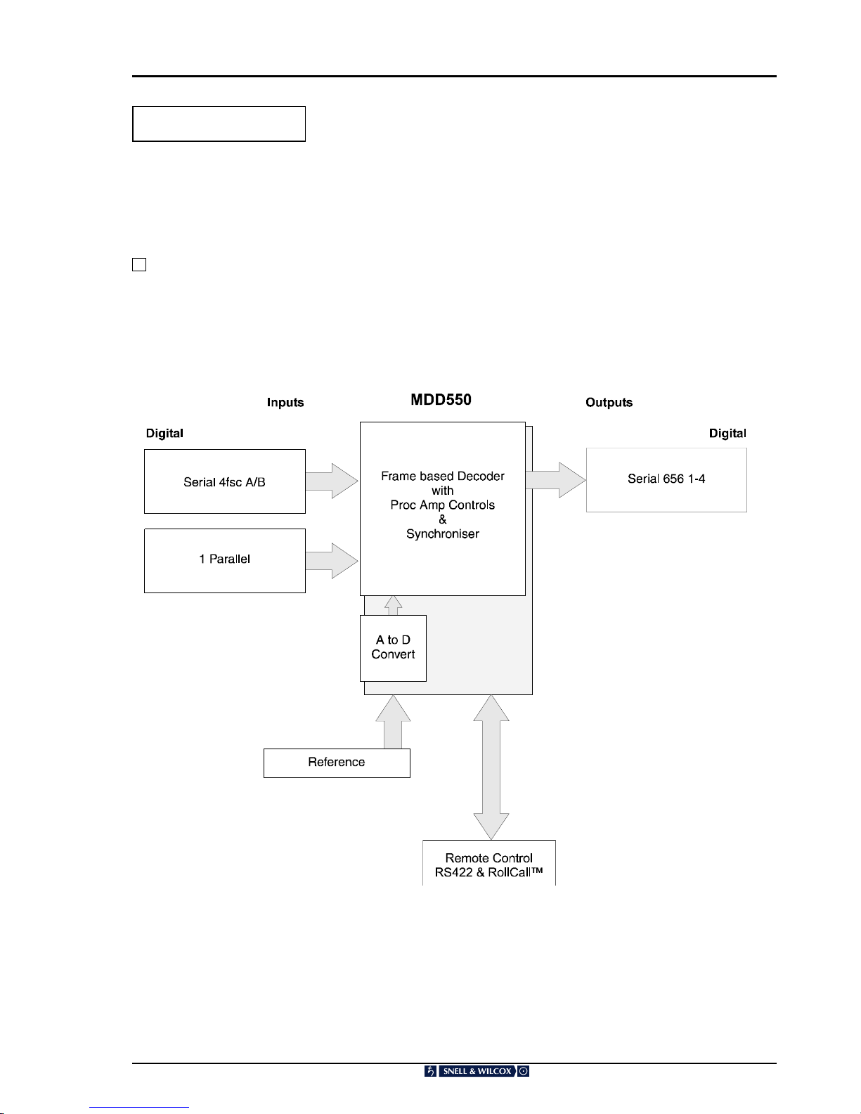
Snell & Wilcox MDD550-70 User manual

MDD550011298 Version 1 Issue 2 0.1
Operator’s
Manual
© December 1998
SNELL & WILCOX LTD, DURFORD MILL, PETERSFIELD, HAMPSHIRE, GU31 5AZ, UNITED KINGDOM.
Tel: +44(0) 1730 821188. Fax: +44(0) 1730 821199.
Snell & Wilcox
MDD550
Series of Decoders -50,-60,-70
Transit Protection-Important Notice
REMOVING THE TRANSIT TIE-WRAPS
When supplied the PCB card will be secured by 2 tie-wraps, looped around the card ejectors and through 2
holes in the base plate. Before installing the rack both of the tie-wraps should be removed by cutting off the
tie-wrap knot and completely removing the tie-wrap.
REPLACING THE TRANSIT TIE-WRAPS
Before shipping, the transit tie-wraps should be replaced with the
spare tie-wraps supplied (part no. RMW610). With the unit
free-standing ensure that the PCB card is pushed fully home
using the card ejectors. From the inside of the unit, feed the
tongue of the tie-wrap behind the card ejector and through the
base plate using the rear of the 2 holes. From the outside, feed
the tongue back through the base plate using the other hole, past
the front of the card ejector, feed through the eye of the tie-wrap,
pull tight and cut off the excess.

Safety Warnings
Always ensure that the unit is properly earthed and power connections correctly made.
This equipment shall be supplied from a power system providing a PROTECTIVE EARTH connection and
having a neutral connection which can be reliably identified.
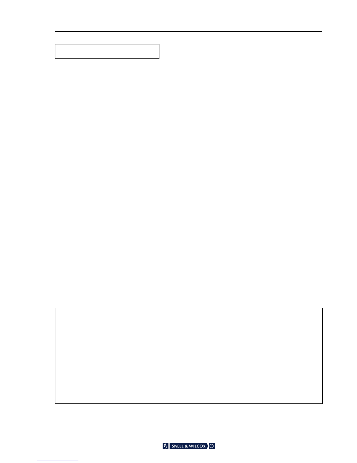
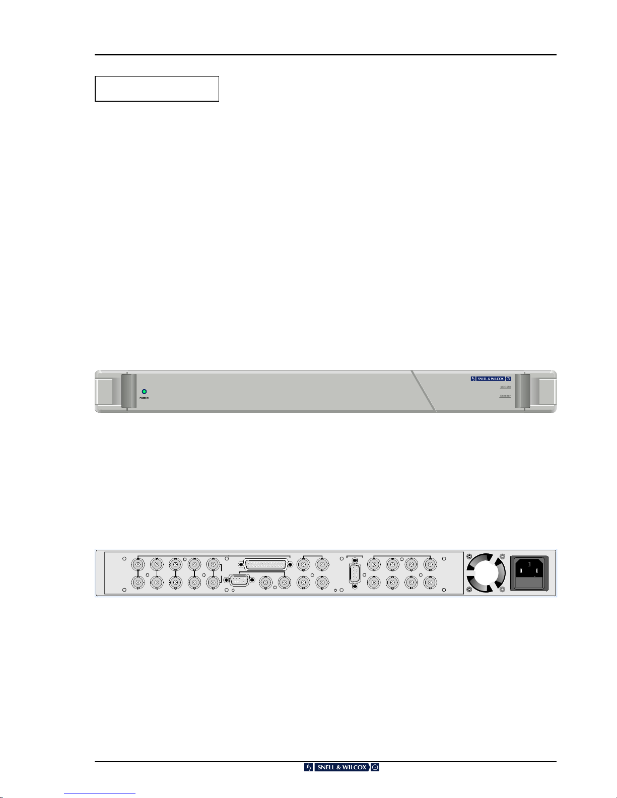
The power terminals of the IEC mains input connector on the rear panel are
identified as shown below:
E = Protective Earth Conductor
N = Neutral Conductor
L = Live Conductor
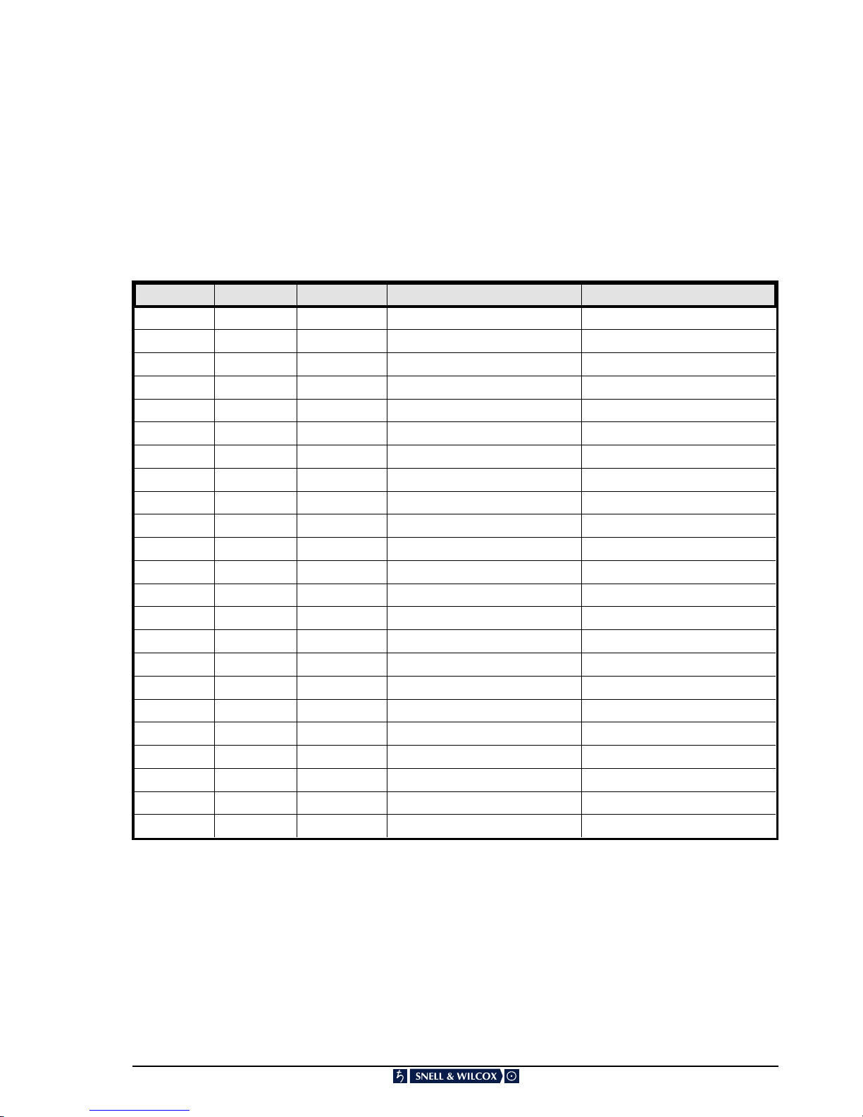
Power cable supplied for countries other than the USA
The equipment is normally shipped with a power cable with a standard IEC moulded free socket on one end and
a standard IEC moulded plug on the other. If you are required to remove the moulded mainssupply plug, dispose
of the plug immediately in a safe manner. The colour code for the lead is as follows:
GREEN/YELLOW lead connected to E (Protective Earth Conductor)
BLUE lead connected to N (Neutral Conductor)
BROWN lead connected to L (Live Conductor)
Power cable supplied for the USA
The equipment is shipped with a power cord with a standard IEC moulded free socket on one end and astandard
3-pin plug on the other. If you are required to remove the moulded mains supply plug, dispose of the
plugimmediately in a safe manner. The colour code for the lead is as follows:
GREEN lead connected to E (Protective Earth Conductor)
WHITE lead connected to N (Neutral Conductor)
BLACK lead connected to L (Live Conductor)
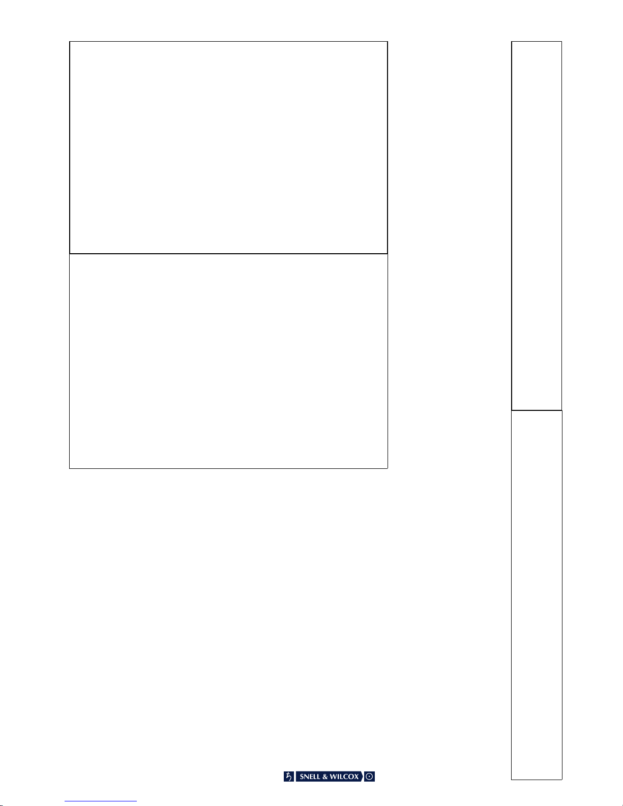
The terminals of the IEC mains supply
lead are identified as shown opposite:
Note that for equipment that is not fitted with a mains power switch, to comply with BS60950 Clauses 1.7.2 and
2.6.9, the power outlet suppling power to the unit should be close to the unit and easily accessible.
No part of this publication may be transmitted or reproduced in any form or by any means, electronic or
mechanical, including photocopy, recording or any information storage and retrieval system, without
permission being granted, in writing, by the publishers or their authorised agents.
Warnings
Voltages within this unit can be lethal under certain circumstances. Where power
is required to be connected to the unit during servicing great care must be taken to
avoid contact with these voltages.
Maintenance should only be carried out by suitably qualified personnel.
MDD550011298 Version 1 Issue 2 Software Version 1.3.1 onwards 0.2

EMC Standards
This unit has been designed to conform to the following standards:
Electromagnetic Compatibility-Generic Immunity Standard BS EN 50082-1:1992
The European Standard EN 50082-1:1992 has the status of a British Standard and is related to
European Council Directive 89/336/EEC dated 3rd May 1989.
Electromagnetic Compatibility-Generic Emission Standard BS EN 50081-1:1992
The European Standard EN 50081-1:1992 has the status of a British Standard and is related to
European Council Directive 89/336/EEC dated 3rd May 1989.
Safety Standards
This unit conforms to EN60950:1992 as ammended by ammendment A1(May 1993)
and ammendment A2(March1994). Specification for safety oftechnology equipment,
including electrical business equipment.
EMC Performance of Cables and Connectors
Snell & Wilcox products are designed to meet or exceed the requirements of the appropriate European
EMC standards. In order to achieve this performance in real installations it is essential to use cables
and connectors with good EMC characteristics.
All signal connections (including remote control connections) shall be made with screened cables
terminated in connectors having a metal shell. The cable screen shall have a large-area contact with
the metal shell.
COAXIAL CABLES
Coaxial cables connections (particularlyserialdigital video connections)shallbemadewithhigh-quality
double-screened coaxial cables such as Belden 8281 or BBC type PSF1/2M.
D-TYPE CONNECTORS
D-type connectors shall have metal shells making good RF contact with the cable screen. Connectors
having "dimples" which improve the contact between the plug and socket shells, are recommended.
CAUTION: These servicing instructions are for use by qualified personnel only. To reduce the risk of
electric shock, do not perform any servicing other than that contained in the Operating Instructions
unless you are qualified to do so. Refer all servicing to qualified service personnel.
MDD550011298 Version 1 Issue 2 Software Version 1.3.1 onwards 0.3

Table of Contents
SECTION
1Introduction
Description . . . . . . . . . . . . . . . . . . . . . . . . . . . . . . . . . . . . . . . . 1.1
Features . . . . . . . . . . . . . . . . . . . . . . . . . . . . . . . . . . . . . . . . . . 1.2
Operational Block Diagram . . . . . . . . . . . . . . . . . . . . . . . . . . . . . . . . 1.3
2Specifications
Input Signals . . . . . . . . . . . . . . . . . . . . . . . . . . . . . . . . . . . . . . . . 2.1
Output Signals . . . . . . . . . . . . . . . . . . . . . . . . . . . . . . . . . . . . . . . 2.1
Technical Data . . . . . . . . . . . . . . . . . . . . . . . . . . . . . . . . . . . . . . 2.2
3Installation
Power Connections . . . . . . . . . . . . . . . . . . . . . . . . . . . . . . . . . . . . 3.1
Communication Connections . . . . . . . . . . . . . . . . . . . . . . . . . . . . . . . 3.2
Input Connections . . . . . . . . . . . . . . . . . . . . . . . . . . . . . . . . . . . . . 3.3
Output Connections . . . . . . . . . . . . . . . . . . . . . . . . . . . . . . . . . . . . 3.4
4Operation
General Information . . . . . . . . . . . . . . . . . . . . . . . . . . . . . . . . . . . . 4.1
Operation using Card Edge Controls . . . . . . . . . . . . . . . . . . . . . . . . . . . 4.2
Menu System Diagram . . . . . . . . . . . . . . . . . . . . . . . . . . . . . . . . . . 4.9
Operation from an active front panel . . . . . . . . . . . . . . . . . . . . . . . . . . . 4.10
Active Front Panel Push Buttons . . . . . . . . . . . . . . . . . . . . . . . . . . . . . 4.12
Menu Details . . . . . . . . . . . . . . . . . . . . . . . . . . . . . . . . . . . . . . . 4.13
Packing List
The unit is supplied in a dedicated packing carton provided by the manufacturer and should not beaccepted
if delivered in inferior or unauthorised materials. Carefully unpack the carton and check for any shipping
damage or shortages.
Any shortages or damage should be reported to the supplier immediately.
Enclosures: * MDD550 series Decoder
* Power cable
* Operator’s Handbook
MDD550011298 Version 1 Issue 2 Software Version 1.3.1 onwards 0.4

Manual Revision Record
Date Version No. Issue No. Change Comments
050398 1 1 First Issue for MDD550 series
011298 1 2 UL data added New manual issued
MDD550011298 Version 1 Issue 2 Software Version 1.3.1 onwards 0.5

Operator’s Manual
Snell
&
Wilcox
MDD550
Series
MDD550-50
MDD550-60
and
MDD550-
70
Operator’s
Manual
Snell & Wilcox
MDD550
Series of Decoders
Covering MDD550-50, MDD550-60 and MDD550-70

SECTION 1
Introduction
DESCRIPTION
The MDD550 series are composite video decoders
which have an adaptive multi-dimensional filter which
can work across 5 fields or in a minimum delay mode.
The MDD550 series comprise:
MDD550-50 NTSC Decoder
MDD550-60 PAL Decoder
MDD550-70 Multi-standard Decoder
Fuse
PANEL ROLLCALL
CONTROL
EDH
COMPOSITE PARALLEL SERIAL OUTPUT CONTROL COMPONENT OUTPUT
PbYPr
Pb/B
Y/G
Sync
3
21
REFERENCE SERIAL
COMPOSITE
INPUT
AAB
LOOP
REMOTE Pr/R
RS422
4
POWER
88-264V(AC)
50/60Hz0.6A
FUSE1A(T)
The units are contained in a single 1U rack case,
meeting current EMC regulations (BS EN 50081-1 for
emission and BS EN 50082-1 for immunity)
Control is via card edge controls or by using the
RollCallremote control system.
MDD550050398 Version 1 Issue 1 Software Version 1.3.1 onwards 1.1

SECTION 1
Introduction
FEATURES
NTSC, PAL and Multi-Standard versions
4fsc to 4:2:2 bridge
Sophisticated adaptive, multi-tap vertical-temporal separation filter
Two 4fsc SMPTE-259 looped inputs
One Parallel 4fsc input
Four Rec656 4:2:2 outputs
Synchronise frame operation
Output may be locked to input
High quality Digital filtering
RollCallcontrol protocol with built-in gateway to RS422
MDD550050398 Version 1 Issue 1 Software Version 1.3.1 onwards 1.2

SECTION 1
Introduction
All 10-bit digital design
OPERATIONAL BLOCK DIAGRAM
MDD550050398 Version 1 Issue 1 Software Version 1.3.1 onwards 1.3

INPUT SIGNALS
Reference Standard Video or black burst via loop-through BNC connectors for 75 Ohms.
Serial Two inputs (A and B ) for Serial Digital via loop-through BNC connectors for 75
Ohms.
Input return loss better than -15 dB @ 270 MHz
An input equaliser contains an automatic equaliser allowing input cable lengths
of up to 150 m when high quality cable is used.
Parallel One input for parallel composite digital video via DB25 connector
Terminatedin110Ohms±10Ohms.10mmaximumcablelengthusingshielded
multi-core cable.
OUTPUT SIGNALS
Serial Digital Four isolated serial digital outputs are available via BNC connectors for
connection to 75 Ohms systems.
Output level 800 mV ±10%
Output return loss better than -15 dB @ 270 MHz
Note that to ensure reliable transmission of serial digital signals without causing
unacceptable levels of radiated emissions, only high quality 75 Ohm co-axial
cable should be used.
The cable must also be terminated with a precision 75 Ohm load.
SECTION 2
Specifications
MDD550050398 Software Version 1.3.1 onwards 2.1

SIGNAL PATH
Digital Input One parallel digital composite input via 25 way DB connector in accordance
with SMPTE 244M (110 Ohm ±10 Ohms)
Two serial inputs for 143 Mbs/177Mbs composite digital video data in
accordance with SMPTE 259M-A via passive loop-through BNC connectors for
75 Ohms.
Return loss better than -15 dB to 270 MHz at all times (active or inactive)
Reference Input Oneinputviapassiveloop-throughBNCconnectorsfor75Ohms.Nominalinput
level 1 V p-p composite video, black burst at standard level or mixed syncs at
2 V p-p.
Return loss better than -35 dB to 5.75 MHz.
RollCallInput OneinputviaBNCconnectorfor75Ohms.ForconnectiontoRollCallnetwork
Rate Conversion All digital rate conversion is performed operating ona data path with a minimum
of 10 bits resolution.
The rate conversion method used is the subject of a Snell & Wilcox patent.
Synchroniser A full 10-bit digital frame synchroniser is incorporated into the main signal
processing path.
The output of the synchroniser may be locked to the input video, the reference
video or allowed to free run.
Control Limited control functions are available from card edge switches with modes of
operation indicated by LED’s.
FullcontrolisviatheoptionalfrontpanelorbyusingRollCallwhichcancontrol
the unit from a P.C. or a remote front panel.
Digital Output Four serial digital outputs are provided via BNC connectors for 75 Ohms.
The serial component digital output is in accordance with SMPTE 259M-C
Return loss is better than -15 dB to 270 MHz.
Power Requirements 90 V to 250 V 50/60Hz A.C. IEC Socket Fused 1A(T)
(Note that EN60950 clause 1.4.5 requires safe operation taking into account
a tolerance of +6% to -10% on this voltage range)
Power Consumption 50VA maximum
Temperature Range 0 to 40°C operating (Unit incorporates a cooling fan)
Mechanical The unit is ruggedly constructed in a 19" 1U steel rack mount case.
Dimensions 483mm x 457mm x 45mm (W, D, H.)
Weight 7 kg
SECTION 2
Specifications
MDD550050398 Software Version 1.3.1 onwards 2.2

POWER CONNECTIONS
This is the IEC320 mains power connector suitable for
a standard IEC type power cable and contains a 1A(T)
fuse. If a fused type plug is fitted to the cable a fuse of
7A (F) rating should be installed.
POWER ON/OFF SWITCH
The power ON/OFF switch is located behind the
drop-down front panel in the left hand corner.
POWER INDICATOR
The green LED indicator on the front panel marked
POWER will be illuminated when the unit is
powered-up.
Fuse
O
WER
6
4V(AC)
0
Hz0.6A
S
E1A(T)
SECTION 3
Installation
MDD550050398 Software Version 1.3.1 onwards 3.1

COMMUNICATIONS CONNECTIONS
CONTROL RS422
This 9 pin ‘D’ connector on the rear panelis the RS422
control connector. Connections are as follows:
Pin 1 Ground
Pin 2 Transmit TXA
Pin 3 Receive RXB
Pin 4 Common (Transmit Signal)
Pin 5 Ground
Pin 6 Common (Receive Signal)
Pin 7 Transmit TXB
Pin 8 Receive RXA
Pin 9 Ground
REMOTE PANEL
This 9-pin ‘D’ connector allows an interconnection to
be made to a remote or other panels in a multiple-unit
system.
ROLLCALL
This single BNC connector allows the unit to be
connected to the RollCallnetwork communications
system.
For more details of the RollCallsystem see Section 1
PANEL ROLLCALL
CONTROL
SERIAL
A
BLOOP
REMOTE
SECTION 3
Installation
SERIAL OUTPUT CONTROL COMP
O
P
Y
P
Y/G
3
2
1
RS422
4
ROLLCALL
CONTROL
MDD550050398 Software Version 1.3.1 onwards 3.2

INPUT CONNECTIONS
REFERENCE
Theunitanditsoutputsignalsmaybereferencelocked
to an external analogue (black burst or composite
video) signal using the ‘REFERENCE’ connector.
This input expects a standard level signal via
loop-through BNC connectors for 75 Ohms. If the
loop-through facility is not used a BNC 75 Ohm
terminating plug should be fitted on the unused
connector.
Note that any reference signal supplied must be
compatible with the operating standard of the unit.
SERIAL
Theseare thetwo Serial Digitalvideo inputs totheunit
via loop-through BNC connectors for 75 Ohms. If the
loop-through facility is not used a BNC 75 Ohm
terminating plug should be fitted on the unused
connector. Nominal input level is 1V p-p.
Either A or B input may be selected using the card
edge controls or via the RollCallremote control
system.
PARALLEL INPUT
This is the parallel composite digital video input to the
unit via a 25 way ‘D’ type connector (DB25)
SERIAL
AB
LOOP
SECTION 3
Installation
REFERENCE
INPUT
COMPOSITE PARALLEL
MDD550050398 Software Version 1.3.1 onwards 3.3

OUTPUT CONNECTIONS
SERIAL OUTPUTS
There are four outputs of Serial digital video available
from the unit via these BNC connectors for 75 Ohms.
Note that the following connectors have no function on
this unit and connections should not be made to them:
COMPOSITE A & B, EDH, COMPONENT OUTPUT
Y, Pb, Pr, Sync, Y/G, Pb/G, Pr/R.
SECTION 3
Installation
PANEL ROLLCALL
CONTROL
EDH
COMPOSITE PARALLEL SERIAL OUTPUT CONTROL COMPONENT OUTPUT
Pb
YPr
Pb/B
Y/G
Syn
3
2
1
REFERENCE SERIAL
COMPOSITE
INPUT
AAB
LOOP
REMOTE Pr/R
RS422
4
SERIAL OUTPUT
3
2
1
4
MDD550050398 Software Version 1.3.1 onwards 3.4

GENERAL INFORMATION
The MDD550 series may be controlled by means of a card edge controls located behind the hinged front panel,
from a suitable active remote front panel or via a computer interface. Remote control is also available via a wired
network system called RollCalland several units may be controlled.
SECTION 4
Operation
MDD550050398 Software Version 1.3.1 onwards 4.1

OPERATION USING CARD EDGE CONTROLS
Adjustment of the settings for the MDD550 series is
available either via card edge controls or via the
RollCallremote control system.
Front Panel Connector
The front panel is connected to the card via this 9-pin
connector.
SW1 and SW2
These push-button switches allow parameters (as
selected by SW3) to be adjusted.
SW1 increases values and SW2 decreases values.
To return to default values both buttons should be
pressed simultaneously.
SW3 Position 0
The input gain may be adjusted in this position.
Adjustment range is from 0% to 117% in steps of 1%
and preset value is 100%.
SW3 Position 1
The chrominance gain may be adjusted in this
position.Adjustmentrangeisfrom0%to200%insteps
of 1% and preset value is 100%.
SW3 Position 2
This position is not used
SW3 Position 3
This position allows the front porch to be adjusted.
In NTSC mode the width may be adjusted in 148 ns
steps. Preset value is 1333 ns.
In PAL mode the width may be adjusted in 148 ns
steps. Preset value is 1333 ns.
SECTION 4
Operation
MDD550050398 Software Version 1.3.1 onwards 4.2

SW3 Position 4
This position allows the back porch to be adjusted.
In NTSC mode the width of the back porch may be
adjusted in 148 ns steps.
Preset value is 4741 ns.
In PAL mode the width of the back porch may be
adjusted in 148 ns steps.
Preset value is 5630 ns.
SW3 Position 5
This position is not used
SW3 Position 6
In this position the vertical phasing or offset between
the reference signal and the output signal may be
adjusted.
In NTSC mode this selection allows the vertical
phasing to be adjusted by ±262 lines in steps of 1 line.
Preset value is 0.
In PAL mode this selection allows the vertical phasing
to be adjusted by ±312 lines in steps of 1 line.
Preset value is 0.
SW3 Position 7
In this position the horizontal phasing or offset
between the reference signal and the output signal
may be adjusted.
In NTSC mode this selection allows the horizontal
phasing to be adjusted in steps of 37 ns.
Preset value is 0 ns.
In PAL mode this selection allows the horizontal
phasing to be adjusted in steps of 37 ns.
Preset value is 0 ns.
SW3 Position 8
This position is not used
SW3 Position 9
(Only available in NTSC mode)
This position allows adjustment of the hue or colour
tint of the picture.
Adjustment range is from -180° to +179° in steps of 1°
and preset value is 0°
SW3 Position A
The horizontal picture position (within blanking) may
be adjusted from this position.
The adjustment in steps of 4 ns and preset value is
0 ns.
SW3 Positions B to E
These positions are reserved
SW3 Position F
In this position operating the push buttons will set all
controls to their factory default values.
SECTION 4
Operation
MDD550050398 Software Version 1.3.1 onwards 4.3

LED INDICATORS
D1 (SOIRX)
This indicator will flash when RS422 data is being
received from the remote control port.
D2 (SIOTX)
This indicator will flash when RS422 data is being
transmitted to the remote control port.
D3 (DAT2)
This indicator will flash when network data is being
received from the RollCallremote control port.
D4 (DAT1)
This indicator will flash when network data is being
transmitted to the RollCallremote control port.
D5, D6, D7 & D8
Theseindicate thatthe -6 V,+5V, +6 V and-5Vpower
supplies are present.
D9 (INPUT)
This indicator will illuminate if the input is present.
D10 (REF)
This indicator will illuminate if the reference signal is
present.
D11 (ERROR)
This indicator will illuminate if an error is detected
e.g. selected input is missing or selected reference is
missing or the wrong standard.
D12 (EDH)
This indicator is non-operational.
D13 (SCL) and D14 (SDA)
These are internal status indicators
D15 (ILF)
This indicator will flash if an internal load fault is
detected;continious illumination indicates a faultyunit.
SECTION 4
Operation
MDD550050398 Software Version 1.3.1 onwards 4.4

SW4
This Hex switch allows various decoder comb modes
to be selected.
Position 0: Studio 1
Thismodeshouldbeusedformoststablestudiosignal
sources
Position 1: Studio 2
This mode should be used for ‘non-sports’ type
material.
Position 2: Studio 3
(Only available in NTSC Mode)
This mode should be used for "real life" type pictures
e.g. sports etc. Use this mode as a starting point.
Position 3: Mindel
This mode produces the minimum input/output delay
(approx 3 lines) and may be used where audio delay
problems may exist and cannot be compensated for.
Position 4:
This position has no function
Position 5:
This position has no function
Position 6: Still
This mode gives best results with sources that contain
no motion. e.g. Rostrum cameras and still graphics.
Position 7: Simple1
This simple decode mode incorporates a wide
bandwidth subcarrier notch filter.
Position 8: Simple2
This simple decode mode incorporates a narrow
bandwidth subcarrier notch filter.
Position 9: Line
This is a classical line comb with no adaption.
Positions A to F are reserved; do not use.
SECTION 4
Operation
MDD550050398 Software Version 1.3.1 onwards 4.5
This manual suits for next models
2
Table of contents
Other Snell & Wilcox Media Converter manuals

Snell & Wilcox
Snell & Wilcox HD200 User manual

Snell & Wilcox
Snell & Wilcox Kudos Plus CVR250 User manual

Snell & Wilcox
Snell & Wilcox Premier HD HD2200 Administrator Guide

Snell & Wilcox
Snell & Wilcox HD2300 Administrator Guide

Snell & Wilcox
Snell & Wilcox HD5050 User manual

Snell & Wilcox
Snell & Wilcox ARC130S User manual