Snell & Wilcox HD200 User manual

HD200200599 Version 1 Issue 5 0.1
Operator’s
Manual
© May 1999
Snell & Wilcox Ltd, Durford Mill, Petersfield, Hampshire, GU31 5AZ, United Kingdom.
Tel: +44(0) 1730 821188. Fax: +44(0) 1730 821199.
HD200
Compact High Definition
Downconverter

HD200200599 Version 1 Issue 5 0.2
Safety Warnings
Always ensure that the unit is properly earthed and power connections correctly made.
This equipment shall be supplied from a power system providing a PROTECTIVE EARTH connection and
having a neutral connection which can be reliably identified.
The power terminals of the IEC mains input connector on the rear panel are
identified as shown below:
E = Protective Earth Conductor
N = Neutral Conductor
L = Live Conductor
Power cable supplied for countries other than the USA
The equipment is normally shipped with a power cable with a standard IEC moulded free socket on one end
and a standard IEC moulded plug on the other. If you are required to remove the moulded mains supply plug,
dispose of the plug immediately in a safe manner. The colour code for the lead is as follows:
GREEN/YELLOW lead connected to E (Protective Earth Conductor)
BLUE lead connected to N (Neutral Conductor)
BROWN lead connected to L (Live Conductor)
Power cable supplied for the USA
The equipment is shipped with a power cord with a standard IEC moulded free socket on one end and a
standard 3-pin plug on the other. If you are required to remove the moulded mains supply plug, dispose of the
plug immediately in a safe manner. The colour code for the lead is as follows:
GREEN lead connected to E (Protective Earth Conductor)
WHITE lead connected to N (Neutral Conductor)
BLACK lead connected to L (Live Conductor)
The terminals of the IEC mains supply
lead are identified as shown opposite:
Note that for equipment that is not fitted with a mains power switch, to comply with BS60950 Clauses 1.7.2 and
2.6.9, the power outlet supplying power to the unit should be close to the unit and easily accessible.
Warnings
Voltages within this unit can be lethal under certain circumstances. Where power
is required to be connected to the unit during servicing great care must be taken
to avoid contact with these voltages.
Maintenance should only be carried out by suitably qualified personnel.
No part of this publication may be transmitted or reproduced in any form or by any means, electronic or
mechanical, including photocopy, recording or any information storage and retrieval system, without permission
being granted, in writing, by the publishers or their authorised agents
.

HD200200599 Version 1 Issue 5 0.3
EMC Standards
This unit has been designed to comply with the following standards:
Electromagnetic Compatibility-Generic Immunity Standard BS EN 50082-1:1992
The European Standard EN 50082-1:1992 has the status of a British Standard and is related to European
Council Directive 89/336/EEC dated 3rd May 1989.
Electromagnetic Compatibility-Generic Emission Standard BS EN 50081-1:1992
The European Standard EN 50081-1:1992 has the status of a British Standard and is related to European
Council Directive 89/336/EEC dated 3rd May 1989.
Safety Standards
This unit has been designed to comply with EN60950:1992 as amended by amendment
A1(May 1993) and amendment A2(March 1994). Specification for safety of technology
equipment, including electrical business equipment.
EMC Performance of Cables and Connectors
Snell & Wilcox products are designed to meet or exceed the requirements of the appropriate European EMC
standards. In order to achieve this performance in real installations it is essential to use cables and connectors
with good EMC characteristics.
All signal connections (including remote control connections) shall be made with screened cables terminated in
connectors having a metal shell. The cable screen shall have a large-area contact with the metal shell.
COAXIAL CABLES
Coaxial cables connections (particularly serial digital video connections) shall be made with high-quality
double-screened coaxial cables such as Belden 8281 or BBC type PSF1/2M.
D-TYPE CONNECTORS
D-type connectors shall have metal shells making good RF contact with the cable screen. Connectors having
"dimples" which improve the contact between the plug and socket shells, are recommended.
Packing List
The unit is supplied in a dedicated packing carton provided by the manufacturer and should not be accepted if
delivered in inferior or unauthorised materials. Carefully unpack the carton and check for any shipping damage
or shortages.
Any shortages or damage should be reported to the supplier immediately.
Enclosures: •HD200 unit
•Power cable
•Operator’s Handbook

HD200200599 Version 1 Issue 5 0.4
INFORMATION TO THE USER
NOTE
This equipment has been tested and found to comply with the limits for a Class A digital device, pursuant to
Part 15 of the FCC Rules. These limits are designed to provide reasonable protection against harmful
interference when the equipment is operated in a commercial environment. This equipment generates, uses,
and can radiate radio frequency energy and, if not installed and used in accordance with the instruction
manual, may cause harmful interference to radio communications. Operation of this equipment in a residential
area is likely to cause harmful interference in which case the user will be required to correct the interference at
his own expense.
CAUTION
Any changes or modifications to this equipment that are not specifically authorised in writing by Snell & Wilcox
could void your authority to use the equipment.
7KLVGHYLFHFRPSOLHVZLWK3DUWRIWKH)&&UXOHV
2SHUDWLRQLVVXEMHFWWRWKHIROORZLQJWZRFRQGLWLRQV
WKLVGHYLFHPD\QRWFDXVHKDUPIXOLQWHUIHUHQFHDQG
WKLVGHYLFHPXVWDFFHSWDQ\LQWHUIHUHQFHUHFHLYHGLQFOXGLQJ
LQWHUIHUHQFHWKDWPD\FDXVHXQGHVLUHGRSHUDWLRQ

HD200200599 Version 1 Issue 5 0.5
Table of Contents
SECTION
1Introduction
Description..........................................................................................................................1.1
Features..............................................................................................................................1.2
Overview.............................................................................................................................1.3
Input-Output Characteristics...............................................................................................1.4
2 Specifications
3 Installation
Power Connections.............................................................................................................3.1
Remote Connections ..........................................................................................................3.1
Input Connections...............................................................................................................3.2
Output Connections............................................................................................................3.3
4 Operation
General Operating Principles..............................................................................................4.1
Menu System Diagram .......................................................................................................4.3
Dedicated Push Buttons
Input........................................................................................................................4.4
Video ......................................................................................................................4.5
Enhance .................................................................................................................4.5
Patterns..................................................................................................................4.6
Utils.........................................................................................................................4.6
Output.....................................................................................................................4.6
Display....................................................................................................................4.7
Genlock ..................................................................................................................4.10
Config.....................................................................................................................4.11
Memory...................................................................................................................4.12
Operating from an active control panel via the RollCall remote control system..................4.13
5 Remote Control
RollCall................................................................................................................................5.1
Control of HD200 with other RollCall Units.........................................................................5.5
6 Operating the HD200 from a remote controller using the RS422 interface ................6.1

HD200200599 Version 1 Issue 5 0.6
Manual Revision Record
Date Version No. Issue No. Change Comments
020798 1 1 First Issue
090798 1 2 Mixed syncs input function
removed –all sections New manual issued
150998 1 3 FCC data added to section 0 New section 0 issued
171198 1 4 Section 6 RS422 interface added New section 0 and 6 added
200599 1 5 To spec, card edge controls
added, input and memory menus
Text changes to 1.3, 1% to 0.1%
2.1, extra standard 4.4, 1% to
0.1% 4.8 & 4.9, page 4.21 to 4.17
4.11, SW2 text 4.16
New section 0, 1, 2, 4 issued

HD200 SECTION 1
HD200200599 Version 1 Issue 5 1.1
Description
HD200
The HD200 is a compact unit that converts any high
definition input to the standard definition equivalent..
It is an ideal camera downconverter, converting a HD
camera into a spatially over-sampled device.
The HD200 offers SDI component digital output with
EDH as standard, and analog component and
composite outputs. Aspect ratio conversion is integral
with pan, tilt and zoom controls allowing the key part
of the HD image to be available at the output. An HD
serial digital component input is available as an
option.
With a three dimensional filter structure, HD200 can
handle interlacing without loss of quality so that those
fine lines in the input are truly resolved. In addition to
automatically sensing the input standard, HD200
allows features such as up to 4 x zoom with pan and
tilt so that the wanted area of the picture can be
enlarged to fill the television screen.
INPUTS OUTPUTS
REF CONTROL
LOOP
LOOP
Y/G Pb/B Pr/R SYNC KEY
MS
12Y
Y
Pb
Pb
Pr
Pr
SERIAL D1 COMPOSITE
REMOTE NET
Y-C
SERIAL D1
Fuse
I
O

HD200 SECTION 1
HD200200599 Version 1 Issue 5 1.2
Features
•Compact interface from HD to SDTV
•All current HD standards supported
•Optional serial digital HD input
•Aspect ratio conversion
•Component digital output with EDH
•Analog component and composite outputs
•Compact: only 2RU
•Low power
•Built-in test patterns
•Full proc. amp facilities

HD200 SECTION 1
HD200200599 Version 1 Issue 5 1.3
Overview
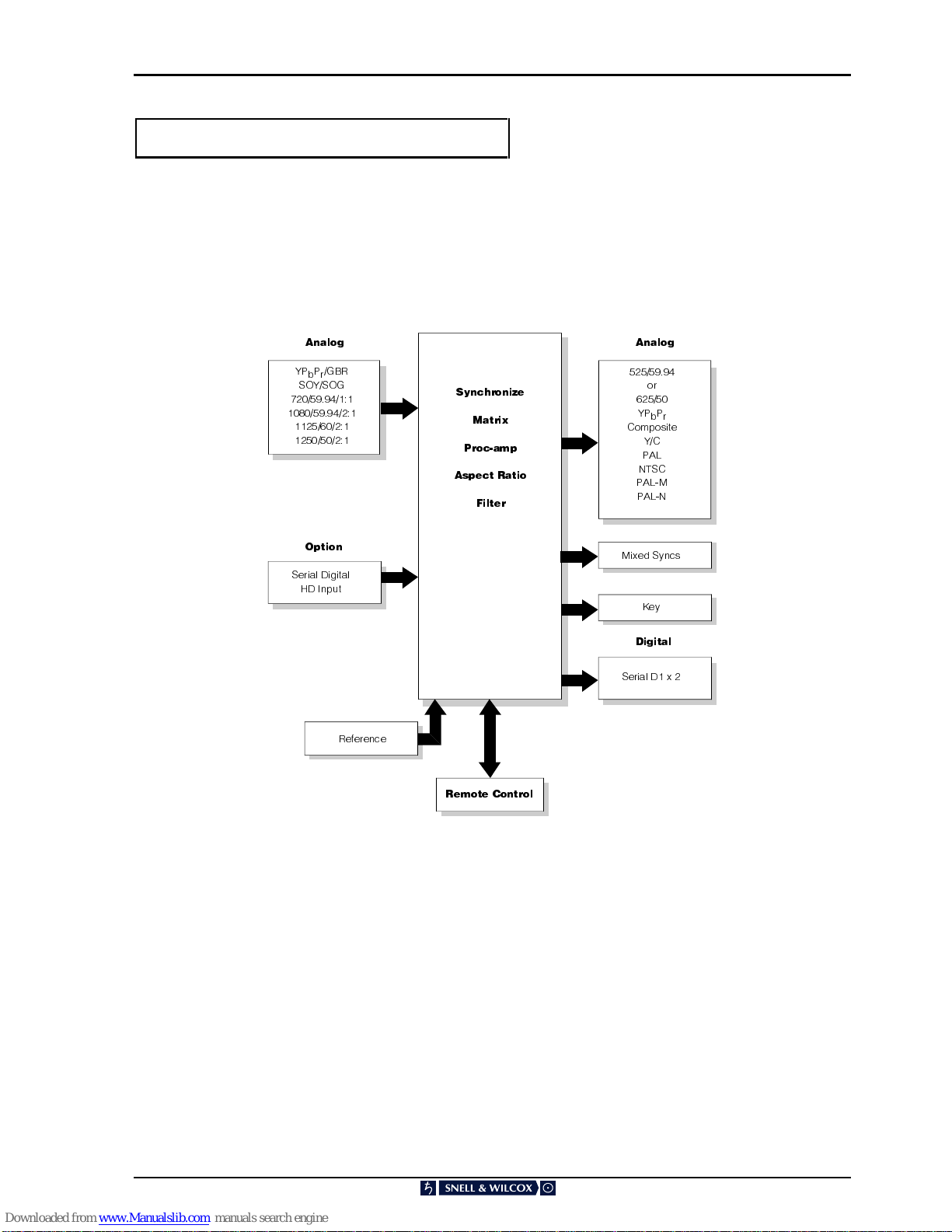
The HD200 from Snell & Wilcox is able to convert a
wide range of high definition formats into standard
TV video without artificial degradation.
The HD200 performs true format conversion. It
does not restrict the operation of the HD source so
that the HD monitor can continue to operate at full
resolution. It uses high quality wide aperture
three-dimension interpolation to perform true scan
format conversion.
Vital to any high quality conversion system is its
ability to handle motion in the graphics. Animated
graphic sequences are nowadays the norm and so
it is no longer possible to use a simple converter
that just drops fields to reduce the field rate to 50 or
60Hz. Converters that use this technique will
introduce unacceptable motion judder. As we
move into the era of virtual studios the motion
portrayal issue becomes even more important.
Even though the input format is high definition the
use of three-dimensional interpolation is necessary
if the resulting output is to be accurately interlaced.
Without this, motion portrayal would suffer. The full
resolution is sampled and stored inside HD200 and
is used to build the necessary output pixels.
The output, by definition, needs to use interlaced
scan as it is a standard TV video signal. Through
the use of Snell & Wilcox’s patented three
dimensional interpolation techniques, the twitter
often associated with interlaced scan is
dramatically reduced leading to stable TV video
that is pleasing to watch.
The correct shaping of the three dimensional filters
is the secret of the HD200’s ability to correctly
anti-alias the video without introducing the softness
often associated with over filtered pictures. This
filter shaping experience has been built up over
years of producing top of the range PAL-NTSC
standards converters.
A range of outputs is available including Serial D1,
YPbPr, Y/C, and analog composite. The
component input is accurately matrixed to fully
compliant broadcast quality YPbPr. Many
adjustments such as black level are adjusted
automatically, but there are also manual controls
available to allow the optional adjustments of some
proc-amp parameters.
A useful feature is the HD200’s ability to zoom in or
shrink the size of video from the HD source and
offset it both vertically and horizontally.

HD200 SECTION 1
HD200200599 Version 1 Issue 5 1.4
Input-Output Characteristics
+',QSXWV 2XWSXWV
$QDORJ
RU
<3E3U
&RPSRVLWH
<&
3$/
176&
3$/0
3$/1
.H\
6HULDO'[
6\QFKURQL]H
0DWUL[
3URFDPS
$VSHFW5DWLR
)LOWHU
$QDORJ
<3E3U*%5
62<62*
6HULDO'LJLWDO
+',QSXW
5HPRWH&RQWURO
5HIHUHQFH
2SWLRQ
'LJLWDO
0L[HG6\QFV

HD200 SECTION 2
HD200100599 Version 1 Issue 3 2.1
Specifications
Features
Signal Inputs
Component One YPbPr with active loop-
through or
one GBRS with active loop-
through
Sync SOG/Y/0.6 V tri-level (loop-
through)
Digital Input (Option) 1.5 Gbits of 1125/59.94/2:1 with
active monitor output
1.75 m of PSF1/2 supported
Reference Composite Video or Black Burst
(loop-through)
Signal Outputs
Digital 2 x Serial D1
Analog 2 x Component YPbPr Chroma
100% saturation 0.7V or 0.93 V
pk to pk
Analog 2 x Composite
Analog 1 x Y-C Separated 4 pin
connector
Sync Mixed syncs at 2 V pk to pk into 75
Ohms
Key 1 V pk to pk (0.7 V luminance,
0.3 V syncs)
High during active video output
Front Panel
Buttons
Input
Video
Enhance
Patterns
Utilities
Output
Display
Genlock
Memory
Preset Controls
Input Standards 1125/59.94/2:1, 1080 active lines
1035 interlaced
1250/50, 1152 active lines
1250/50, 1080 active lines
720 progressive
Input Chroma
Standards Pass through, SMPTE 240,
SMPTE 274, BT709
Input Aspect Ratio 16:9
Analog Input YPbPr/GBR
Sync Input SOG/SOY
Features
Output Standards 525/59.94/2:1, 625/50/2:1 Aspect
Ratio 4:3
Y/C Timing -200 ns to +100 ns in 37 ns steps
Luminance Gain ±3 dB in 0.1 dB steps
Black Level ±50 mV in 2 mV steps
Chrominance Gain ±3 dB in 0.1 dB steps
Patterns 100% color bars
100% bars and red
Cross hatch
Multi-burst: 0.5, 1, 2, 3, 4, 5 MHz
10 steps
Valid Ramp
PLUGE
White
Black
Utilities Monochrome, freeze, fade-to-
black; fade time cut to 10 s in
500 ms steps
Display Size, Zoom and
Aspect Separate horizontal and vertical
size controls;
77.5 to 500% scale in 0.1% steps
Pan Control ±90% of input picture in 0.1%
steps
Tilt Control ±75% of input picture in 0.1%
steps
Aspect Ratios 16:9 to 4:3 conversion using
letterbox
16:9 to 4:3 conversion using side
curtains
Genlock Horizontal
Timing ±32 µs in 37 ns steps
Genlock Vertical Timing +4, -8 lines in 1 line steps
Transition time for size
changes Variable to 4 s in 20 ms
increments
Memory 4 x user memories storing all
parameters.
Variable transition time for size
variations 4 s in 20 ms increments
SC-H Phase Fixed at 0°
Aperture Correction Separate horizontal and vertical
filtering corrections
-3 to +1 vertical filters -3 to +4
horizontal filters
Gamma -4 to +5 tables to change gamma
of Luminance outputs
Remote Control
Full control via
RollCall™ system by a
KUDOS IQ active front
panel or RS422
computer interface

HD200 SECTION 2
HD200200599 Version 1 Issue 4 2.2
Specifications
Video Processing 8-bit 4:2:2
Aperture Spatio-temporal
2T Pulse to bar ratio k-
rating Better than 1%
2T Pulse response k-
rating Better than 1%
Tilt Better than 1%
Residual Jitter < ±10 ns
Y/C Timing Error ±10 ns
Reference Input Return
Loss Better than 38 dB at 4.5 MHz
Analog Blanking
Timings 525 Horizontal: Front porch 1.7 µs,
back porch 9.4 µs Blanking total
11.1 µs, 708 active line samples
Vertical: 1st line 21/283, active
lines 483
Analog Blanking
Timings 625 Horizontal: Front porch 1.5 µs,
back porch 10.5 µs
Blanking total 12.0 µs, 702 active
line samples Vertical: 1st line
23/336, active lines 574
Digital Blanking Digital blanking option selects 720
active samples; analog blanking
timings are correspondingly
reduced
Output Rates 625/50/2:1 or 525/59.94/2:1
interlaced
Output Standards PAL/NTSC/PAL-N
Bandwidth (YPbPr) 8.0 MHz -3 dB, 4.0 MHz -0.1 dB
Bandwidth (Composite) 6.0 MHz -1 dB
Composite or Black
Burst Reference Level Standard level ±6 dB
Power
Rated Voltage Range 88 V to 264 V 47/65 Hz A.C.
Consumption 150 W maximum.
Mechanical
Temperature range 0 to 40° C Operating
Case Type 2U Rack Mounting
Dimensions 483 mm x 450 mm x 89 mm (w,d,h)
Weight 10kg

HD200 SECTION 3
HD200090798 Version 1 Issue 2 3.1
Installation
POWER CONNECTIONS
This is the IEC320 mains power connector suitable
for a standard IEC type power cable and contains
a 1A(T) fuse. If a fused type plug is fitted to the
cable a fuse of 5A (F) rating should be installed.
POWER ON/OFF SWITCH
The power ON/OFF switch is located on the rear
panel combined with the fuse holder and mains
inlet.
ROLLCALL™
This single BNC connector allows the unit to be
connected to the RollCall network communications
system. For more details of this system see
Section 2 `Remote Control’
REMOTE
This 9 pin `D' connector on the rear panel is the
remote control connector that allows specific
functions to be controlled remotely.
Fuse
I
O
NET
C
O
NTR
O
L
REMOTE

HD200 SECTION 3
HD200090798 Version 1 Issue 2 3.2
INPUT CONNECTIONS
G/Y, B/Pb, R/Pr (GBR/YPbPr Component Inputs)
Component RGB or YPbPr inputs are accepted via
these three sets of active loop-through BNC
connectors for 75 Ohms.
Input signals should be connected to the upper set
of connectors. Buffered signal outputs are
available from the lower set of connectors.
For RGB signals
Connect Green signal to the G/Y connector
Connect Blue signal to the B/Pb connector
Connect Red signal to the R/Pr connector
Signal levels are 0.7V p-p into 75 Ohms with syncs
on the green channel.
For YPbPr signals
Connect Y signal to the G/Y connector
Connect Pb signal to the B/Pb connector
Connect Pr signal to the R/Pr connector
Signal levels are 0.7V p-p into 75 Ohms with syncs
on the Y channel.
Sync
These connectors have no function on this unit.
Selection of Input Sync Format
This Input button allows, via the Input Syncs
menu either Syncs on green/Syncs on Y, or Digital
HD syncs to be selected.
INPUTS
Y/G Pb/B Pr/R
LOOP
SYNC

HD200 SECTION 3
HD200090798 Version 1 Issue 2 3.3
REF (Reference Sync Input)
The unit and its output signals may be reference
locked to an external analogue (black burst or
composite video) signal using the ‘REF’ connector.
This loop-through input expects a standard level
signal and should be terminated in 75 Ohms.
Note that any reference signal supplied must be
compatible with the operating output standard of
the unit.
OUTPUT CONNECTIONS
YPbPr (Component Outputs)
2 sets of component YPbPr signals are available
from these BNC connectors at 75 Ohms
impedance.
Pb and Pr signal levels are 0.7V p-p and the Y
signal is 1 V p-p (0.7 V video and 0.3 V syncs) into
75 Ohms.
Y-C
A Y/C separated luminance/chrominance type
signal is available via this 7-pin dub type connector
for 75 Ohms.
Y level is a nominal 1V p-p into 75 Ohms and C
level is a nominal 0.3V p-p colour burst into 75
Ohms.
CVBS (Composite Outputs)
2 sets of composite video signals are available at
standard level from these BNC connectors at 75
Ohms impedance.
REF
LOOP
Y
Y
Pb
Pb
Pr
Pr
OUTPUTS
12Y
Y
COMPOSITE
Y-C
OUTPUTS
12COMPOSITE

HD200 SECTION 3
HD200090798 Version 1 Issue 2 3.4
D1 (Serial D1)
2 sets of Serial Digital Video (D1) signals are
available from these BNC connectors at 75 Ohms
impedance.
KEY (Output)
This connector provides a luminance signal at
standard level (0.7 V video and 0.3 V syncs) that
represents the location of the active picture within
the screen area.
The signal will be high during active picture time
and low at other (picture blanking) times as
illustrated opposite.
This signal may be used for feeding the key or
DSK input of a vision mixer, especially when the
picture has been zoomed out and another picture
is used as a background.
MS (Mixed Sync Output)
This BNC connector provides an output of
standard mixed syncs. The output may be an
analogue signal for 75 Ohms at 2 V p-p or a TTL
compatible signal, selected by internal links.
SERIAL D1
SERIAL D1
OUTPUTS
KEY 1 2COMPOSITE
R
E
F
MSSERIAL D1

HD200 SECTION 4
HD200200599 Version 1 Issue 5 4.1
Operation
GENERAL OPERATING PRINCIPLES
The HD200 may be operated by three methods:
1. By using the front panel controls
2. By using a remote control panel via the
RollCall control system
3. Card edge controls
OPERATION USING THE FRONT PANEL
CONTROLS
All operational parameters and selections may be
made by pressing dedicated push buttons and
selecting items from a system of menus displayed
in the Plasma Display window.
Menus are selected by push buttons and and/or the
spinwheel.
The spinwheel also allows continuously variable
parameters, e.g. Gain, to be adjusted and the
numerical value or setting to be seen in the
window.
Various specific menus may be selected by
operating dedicated push buttons.
The two rows of vertical buttons either side of the
display panel allows selections to be made from
the adjacent menus. The item will become
highlighted when enabled.
The example opposite shows that Zoom function
selected.
The left and right arrow-headed buttons allow
menu items (e.g. Zoom, Aspect, Pan etc.) to be
selected in a left-to-right or right-to-left direction.
The example opposite shows that the Zoom
bargraph has been selected.
The value of this function may then be adjusted
using the spinwheel and the numerical value
indicated below the bargraph display.

HD200 SECTION 4
HD200200599 Version 1 Issue 5 4.2
GENERAL OPERATING INFORMATION
Display Window
The control window displays all selection menus
sub-menus and unit status information.
A selection is made by pressing the button
adjacent to the required item and will become
highlighted (reversed text) when active.
Pressing the Home r button will display the
home status screen in the display window from any
position in the menu hierarchy.
It will display the current system set-up including
the status of input and output signals.
The Back r button allows a return to the last
menu item that was
changed
. Up to 20 changed
menu items may be retraced using this function.
Preset r
Pressing this button will return all settings of the
displayed menu to zero or default settings.
Home Display
In: 1080 Interlaced
Out: 525 59.94 2:1
Freeze ➠Input Loss

HD200 SECTION 4
HD200200599 Version 1 Issue 5 4.3

HD200 SECTION 4
HD200200599 Version 1 Issue 5 4.4
USING THE DEDICATED PUSH BUTTONS m
(see HD200 Menu System opposite)
Various specific menus may be selected using
these push buttons.
When pressed the relevant menu will appear in the
display window.
mINPUT
This button will display a list of input signal
selections available.
The correct input format, sync derivation and input
rate for the connected signal are chosen from this
menu.
Input Rates that may be selected are:
1080 Interlaced
1035 Interlaced
720 Progressive
1125 50 1080
1250 50 1152
1250 50 1080
Input Syncs that may be selected are:
Digital HD Syncs derived from the HD
video input (if fitted)
Sync on G/Y Syncs derived from the signal
connected to the G/Y input
Input Formats that may be selected are:
GBR Component Green, Blue and
Red video signals.
YPbPr Component luminance and
color difference video signals.
Signal connections are made via the BNC
connectors marked Y/G, Pb/B, PrR
Input Chroma may be either:
Pass Thro Chrominance is passed through
the unit
SMPTE 274 Chrominance is processed from
SMPTE 274 requirements
SMPTE 290 Chrominance is processed from
SMPTE 290 requirements
BT709 Chrominance is processed from
BT709 requirements
Table of contents
Other Snell & Wilcox Media Converter manuals

Snell & Wilcox
Snell & Wilcox MDD550-70 User manual

Snell & Wilcox
Snell & Wilcox ARC130S User manual

Snell & Wilcox
Snell & Wilcox Premier HD HD2200 Administrator Guide

Snell & Wilcox
Snell & Wilcox HD5050 User manual

Snell & Wilcox
Snell & Wilcox Kudos Plus CVR250 User manual

Snell & Wilcox
Snell & Wilcox HD2300 Administrator Guide
Popular Media Converter manuals by other brands

Viessmann
Viessmann 5285 Operation manual

Johnson Controls
Johnson Controls FX-BTCVT Series Commissioning Guide

Adtec
Adtec Edje-2000 user manual

SEW-Eurodrive
SEW-Eurodrive MOVITRANS TPM12B operating instructions

Atlona
Atlona OmniStream AT-OMNI-512 manual

Transition Networks
Transition Networks FBRM1XXX-1XX manual